6036E PCMCIA + DAQmx (analog input) seems to only read in blocks of 512 samples of data
Hello people,
I ask this question before I post any code or software versions etc to see if there is a simple answer.
I use a PCMCIA card 6036E to read an analog input channel (DAQmx... i. e create task, create the channel, set the altimeter (continuous samples), task, read in a programmed software loop while (ASAP)). No matter how I put my sample rate, number of samples per channel (i.e. size of buffer), or the number of samples to be read, it looks like I can get multiples of 512 samples.
Here are some samples freq (Fs), the 'number of samples to read' asked and the actual number of samples read:
FS numberOfSamplesRequested numberOfSamplesActuallyRead
200Hz 20 512
1000 1024 5000Hz
2000 2048 5000Hz
QUESTIONS RELATING TO THE:
1 is this 'normal' behavior a 6036E PCMCIA card?
2. in the case, has anyone who may have seen this problem determined the cause and how to "fix it"?
Best regards
Chris
chassan wrote:
Hello people,
QUESTIONS RELATING TO THE:
1 is this 'normal' behavior a 6036E PCMCIA card?
Sort of.
2. in the case, has anyone who may have seen this problem determined the cause and how to "fix it"?
Best regards
Chris
Systems PCI DMA is used to transfer
the data, daqmx and receive messages when the number of samples are
acquis. Now on PC-card that does not work and the data is transferred
When the edge buffer is full (after 2 k of data) to 2 channels
10 Hz, it can take some time.
There is a work-around, there is a property where you can set the transfer mechanism (I have not daqmx on this PC), or the daqmx polling mechanism. Try these.
Found a document KB.
Tone
Tags: NI Software
Similar Questions
-
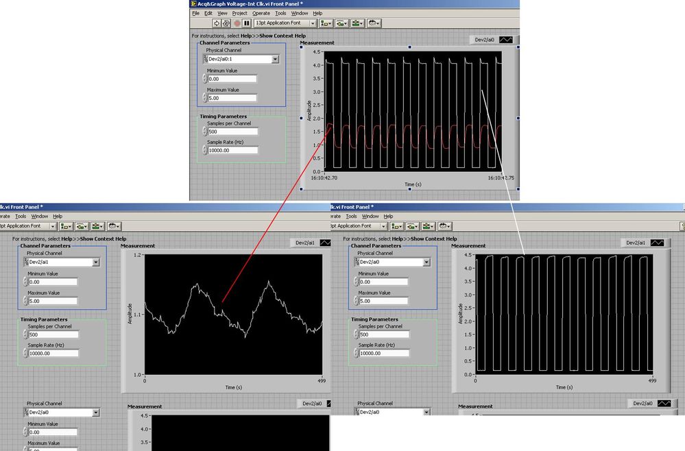
Several analog inputs seem to change any of the other (details DAQ: 2120 BNC and 6062E)
I use the BNC 2120 DAQ board connected to the data acquisition card 6062E to record two analog inputs. An entry is connected to ai0 and the other at ai1. Example vi: "Acq & graph int clk tension" has been used to measure the two entries with the value read NChan NSamp vi (channels being dev2 / ai0:1). The output is the top graph in the image. However, this seemed a bit strange to me that one of them should be modulating with a different frequency. When I record both entered individually (two in low pictures) they are indeed different since the entries shown in the top graph.

Why this would be the case, and how can I overcome this to measure the real signals?
Thank you!
The E series card takes the samples as soon as possible. Thus, for example,.
If you have 16 analog input channels but you only read of
channel 0 and 1, the map will show the channels 0 and 1 right
After and then wait 14 'ticks '. What's that little run-in
the origin of the afterglow.
I think you can get the card to wait a certain
number of ticks with a property node. I have attached a screenshot. You
can find the property node in the palette of functions >
Measurement of e/s > NOR-DAQmx > node Timing. Expand it
Property node so there's two entrances. The properties are in
Left click on the node and going more > converted >
Its properties delay units and sampling clock delay and delay that
you want.If the phase is important so the above is not the best
the option because it causes a delay in phase. So, if you need true simultaneous
sampling, then you will need different hardware. The S series is everything
simultaneous sampling.Or, rather than the Delay property and delay units, try the Rate property
find more > converted > rate.If this is not
work either, you can move the second signal source to, say, AI8 and
Connect everyone to the ground. Readings for these, but just do not take into account
the data. In this way the ADC will sag to the ground at the time where that can happen
the second string in the way so that you should not see this frequency
ghosting on the other channel. -
Full scale PXI - 6254 DAQmx Analog Input
Hello
I use PXI - 6254 Board to read the analog inputs. Configured channels using DAQmx create Channel.vi with sub parameters.
In the configuration: CSR
Min: 0
Max: 10
Units: Volt
I read the channel using DAQmx Read U16 2D with the sample of 1. I expected below the values.
data of 0 v = 0
10 volts = 65535 data
but it gives 10 volts = 31544 data. Please let me know why.
If I set up the channels with the settings below:
In the configuration: CSR
Min:-10
Max: 10
Units: Volt
He always reads the same values (data 0 v = 0, 10 volts = 31544).
Please let me know, how I can get 10 volts = 65535
Thank you
Hi LVTestek,
The PXI-6254 is not an interval 0 to 10 V input V. The specification of 625 x OR lists the available input ranges:
Entry level of ± 10 V, ± 5 V, ±2 V, ± 1 V, ±0, 5 V, ±0, 2 V, ±0, 1 V...
When you set Min = Max 0 = 10, DAQmx chooses the smaller input range that allows to measure signals between 0 V and 10 V without clipping. On the PXI-6254, the smaller input range that meets this criterion is the range of ± 10 V, where - 10 V corresponds to-32768 0 V corresponds to 0 and 10 V corresponds to 32767.
However, there is an additional complication: ranges entry on M Series devices are slightly wider to accommodate the software calibration. Otherwise, gain of a device could reduce the scope of actual entry, and offset error would move the ends of the effective input range. If the [-10 V...] 10 v] range on your PXI-6254 could be more like [-10.3 V...] 10.4 V]. 10 V is actually to 31544, rather than 32767. On another PXI-6254, 10 V could correspond to a different value of gross / scaleless and 31539 31552.
Another side effect of calibration of the software, is that the data returned by the flavours 'raw' and 'no' to the VI DAQmx Read are benchmarked. The KB explains further: is raw data DAQmx calibrated or chipped?
If you can modify your application to use one of the flavors "on the scale" (F64) VI DAQmx read, which should save a lot of effort. If not, could you explain why your program requires readings without scales/bullies? The right approach depends on the requirements. For example, if you want to save the data in a file and you need to reduce the file size by using raw data / scaleless, configuration DAQmx to save data directly a TDMS file can meet your needs. If you update an older application to work with DAQmx and M Series, a different approach may be more appropriate.
Brad
-
DAQmx: Analog input directly to the analog output at the hardware level
Hi all
I searched for a while, but I couldn't find any suitable implementation for what I'm trying to do. A person where I work introduced me to an interesting challenge. Is there a way to set up a DAQmx task (or set up otherwise an MIO Board) to route an entry directly to an output to the analog analog hardware level? You may be thinking, "why the hell would you do? To reduce the electrical complexity, a colleague would like to concurrently read an entry while 'reproduction' of its signal on analog analog output. I know that I can easily accomplish this while the buffering by the PC, but they are interested in ensuring that the output signal is also similar to the input at the level of KHz signal, by introducing a minimal difference in phase (shift buffering of the PC).
For the record, we have for most old maps of the E series here like the PCI-6070E (PCI-MIO-16-1). I was first asked if it could be done through SCXI, but I figured I would start by asking about the MIO tips.
This looks like a long shot, and I've never heard of someone at - he never did this, but I thought I'd ask to be sure!
Thank you
Jim
Hi Jim,.
With the help of our driver is not a means of generating data directly from the FIFO of AI, it must first pass through the software. You can try the following code to the output of one of THE duplicate on the AO line to see what kind of delay you can imagine. It is similar to your original with a few adjustments code:
Use delayed output Version of avian influenza in DAQmx AO
It seems you need to do, you might consider instead the search by using a voltage follower to isolate the Vout wine.
Best regards
John
-
The use of more than 16 analog inputs of a module?
Happy new year to everyone.
The analog input module OR-DAQmx can only support up to 16 channels. Now serveral DAQ cards provide more than 16 channels, including PCI - 6259M offer 32 entered analog.
So, how do dasylab (Ver 11) support more than 16 channels in a NOR-DAQmx analog input module?
Hello srm2003,
(1) build your task NI MAX for your camera - 6259 - 01.png.
(2) DASYLab: Take a first OR-DAQmx analog input module, choose the task of MAX and configure the channels 0... device 0 15... module 15 - photo 6259 - 02.png.
(3) DASYLab: Take a second NOR-DAQmx analog input module, choose the task of MAX and configure channels 16... device 31 0... module 15 - photo 6259 - 03.png.
(4) now you have 2 HAVE modules to manage channels 0... 15 (first) and 16... 31 (second).
Best regards
MHa -
15-20 time of latency to see the changes in analog inputs
I inherited a program extremely complex. I find that I see 15-20 seconds latency on the changes to the analog inputs. I can't post the code - (it has more than 200 sub screw) but I have captured the relevant section in the long latency period of the changes.jpg of analog input attached.
I tried to change the sampling rate and see the same problem from 1 Hz to 25 Hz (limit of reliable sampling with this PC). I'm looking at indicators which are directly related to the acquisition of data Read.vi as evidenced by the big red arrow.
I modeled the nested struct in the template attached without latency problems.jpg. There is no perceptible latency but it duplicates the nested structures.
The only thing not shown is that there are several cases of Read.vi of data acquisition using the same physical changes but not of them are in the loops that need to run at the same time.
The data are consistent with the entries, just delayed.
The Signal processing device is a USB-6343. I am running these screws on LabVIEW 2011 edition.
Any ideas?
Yes, instead of getting just 1 sample buffer, try to get all the samples.
Then you can retrieve the most recent example of all the samples you get and take the rest of them.
Or you can change the configuration of taks for only once every time that you call the read function.
-
Frequency measurement of analog input using DAQmx C APIs on SMU-6341 map
Hello
I use Linux DAQmx and attempt to measure the frequency of analog input using the map DAQ SMU-6341.
There is an ANSI-C frequency measurement example:
/ usr/local/natinst/nidaqmx/examples/ansi_c/Analog_In/Measure_Frequency/Cont_Freq-Int_Clk-SCXI1126
However, the call to DAQmxCreateAIFreqVoltageChan results in the following error:
DAQmx error: selected physical channel does not support the type of measure required by the virtual channel you create.
Create a channel to a type of measure that is supported by the physical channel, or select a physical channel that supports the type of measure.
Property: DAQmx_AI_MeasType
Required value: DAQmx_Val_Freq_Voltage
Possible values: DAQmx_Val_Current, DAQmx_Val_Resistance, DAQmx_Val_Strain_Gage, DAQmx_Val_Temp_BuiltInSensor, DAQmx_Val_Temp_RTD, DAQmx_Val_Temp_Thrmstr, DAQmx_Val_Temp_TC, DAQmx_Val_Voltage, DAQmx_Val_Voltage_CustomWithExcitationTask name: _unnamedTask<0>
State code:-200431
DAQmx does support the function of the frequency on the map 6341, or should we use examples of voltage and calculate the frequency manually?
Frequency of HAVE it is a type of channel that has been supported only on the SCXI module name of the example.
You will need to use a voltage input channel and calculate the frequency manually for your device.
-
Medium-sized dynamic data analog input read DAQmx read
Hi, I'm new to labview. Is there an easy way to index using the dynamics of data returned by a readout DAQmx x samples to calculate a moving average? My thought was to read the analog input for X samples pump with the data in another loop through the data, but I can't quite understand how index using the returned data set to extract the measurement value double returned for each sample.
Any ideas on that?
Thank you...
If you get a type of waveform data, why did you ask on dynamic data? No, of course not would you use the conversion of dynamic data on a waveform.
If you want only one channel, then your DAQmx Read could be changed to 1Chan NSamp. If your channel list only has one channel, you will get a table 1 d with a single element that can be indexed. To get the average of a waveform use the statistical function with the waveform. You use the average Point by Point, and not the average function that has a table for an entry.
Make sure you always have context-sensitive help on. You can avoid many of these rookie mistakes simple.
-
Analog inputs measures with NI6229 using the DAQmx driver
Hello
I have four different analog inputs connected to ai0 to HW 6220 ai3. I read these values with a single task, all 4 channels assigned to this task. When ai0 reads 7V, I see 0.8 V ai1 too, but I expect to be measured 0V. If I just assign ai1 to the task and measure all 4 channels, then I measured 0V as expected (although ai1 contains 7V, I just don't measure it).
Another comment 'funny', is that if I change the order in which I add channels to the task, measurement errors are different.
However, when measured with a multimeter 4-channel show tensions as expected.
Given that my calling task is can not block, I call the function
DAQmxReadAnalogF64 with timeout = 0 and numSampsPerChan = 1.
Any help is appreciated.
Thank you
Kind regards
Deepa
Deepa,
Thanks for the code snippet.
When you call DAQmxReadAnalogF64 the first time and you set a value of timeout of 0, there is a chance that the acquisition is not yet initialized. This is the expected behavior and should not be a problem. If the timeout error died at the first call, you might ignore it or set a different expiration time for the first call only. In all cases, you should drop the first value and start with the second value.
Jochen
-
LabVIEW think my NI USB-6008 has only analog inputs
I am using an NI USB-6008 box to run a route of analog input and analog output.
If I do a constant material DAQmx channel and out the finger tool and pull down... and it offers me 8 analog inputs on Dev1 and nothing else. I've nothing else connected to this computer, but the box USB-6008. A USB-6008 doesn't even have 8 analog input channels.
I'm a bit confused.
-
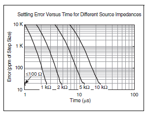
Why a task of analog input shows shape of different signal than DAQmx Test Panel?
I have a DAQ SMU-6363multifunction material. I need to view CHA and CHB with an encoder. I had connected CHA ai4 + and CHB ai5 + thanks to a SCC-68 in differential mode box. I provide + 5V from the power supply of the PXI-4110 of the encoder. I have connected ai4 - and ai5 - to the MASS of the power of the encoder on SCC-68 screw terminals.
PROBLEM: When I create a TASK acquires of ai4 and ai5 at the same time, the shape of the signal is distorted. See picture attached.
If I look at signals with an outer scope touch screw terminals, the signals have the form correct and without distortion.
Also, if I look at one of the signals with Test DAQmx Panel I n MAX, I know the form correct and without distortion.
I have also included a snippet of my code.
Is something wrong with my SMU-6363?
Only one channel at a time on the 6363 acquisition would give you the sampling frequency of 2 MHz. However, the rate of the overall sample is only specced to 1 MHz, due to the time constraints of the used multiplexer compaction.
What you see, it's probably due to ghosting, and it should happen in the test panels as well if you measure two channels at once. This happens if you don't leave enough time for the channels to settle after multiplexing. Here is a table of specifications of 6363 which indicates the time of settling for various source impedances:
In your first picture as an attachment, the error is about 500 mV on a stage of 5V. It would be 10 per cent, or 100 000 ppm.
The same image, I see that you set a frequency 200 kHz 2 channels sample clock. Thus, the sum of 400 kHz to 2.5 would allow us to decide between channels.
Looking at the chart above, (2.5 US, 100 ppm k) is off the chart, but if extrapolate you the curves we could wait for your source impedance is somewhere around 5-10 kohm. Is this correct? If you have a link to the datasheet for your encoder, I'd be happy to take a look.
You do not see the error at 40 kHz 2 channels because it allows up to 12.5 US (1/80 kHz) for the settlement - in fact, DAQmx as default 11 us maximum convert the 6363 period when you buy slow enough to allow the time of settling in this case would be so 11 US. If you had to, you can reduce the clock rate to convert manually via a property node DAQmx Timing if 11 that we by default does not allow enough time for your application. The maximum conversion period which by default is DAQmx is the inverse of the maximum speed of the overall sample (in your case, 1 / 1 MHz = 1 US) + 10 to the United States.
Article ghost link above has some suggestions to eliminate ghosting, the most likely solution for you would be to implement a voltage follower if you need to acquire higher rates than allows the regulation of the multiplexer in view of your signal source. The voltage follower allows to considerably reduce the impedance as seen at the entrance of the DAQ card.
Best regards
-
Toggle the analog inputs and tasks of output on the same card in LabView
Hello
I'm relatively new to LabView and am trying to find the best way to switch between reading and writing tasks on my PCI-6024E. It seems this would be a common thing to do, but I found no good documentation or any relatable example program. Basically, I would like to be able to monitor certain analog inputs and then write that some outputs if an entry is in accordance with certain specific conditions (say > 4 Volts voltage). It is my understanding that you can only signal (input and output) types associated within a single task in DAQmx. I also understand that you cannot have multiple tasks running at the same time on the same material/map, otherwise you get a: 50103 error 'The specified resource is reserved. Calendar is not really all that matters to me, but quite synchronous and effective would be nice.
I have attached a sample program that shows more or less what I'm trying to do. I want to follow several analog input lines (AI0 AI1, AI2 and AI3 and) effectively at the same time. If certain conditions are met, AI3 > 4 Volts, then write 5 Volts for analog AO0 and AO1 outings. I also want to maintain output at 5 Volts up to AI3 falls below 4 Volts. Is there a better way to pass the task to read and write than what I've done here? In a sense, all I really do is toggle of a state machine if the required conditions are met and if start/stop tasks of reading/writing necessary.
One last question, is there a way to display the four channels in the waveform graph using the 1 d NChan 1Samp mode so I can have a time chart and indicators?
P.S. I'm under LabView 2011 on Windows 7. Your ideas and suggestions are appreciated.
Thank you
KJ
I also understand that you cannot have multiple tasks running at the same time on the same material/map, otherwise you get a: 50103 error 'The specified resource is reserved.
This is incorrect. You can't have two tasks of the same type running on a single card. You can have an analog input and analog output task running simultaneously on the same hardware.
You are right that each task can have only one type of task (entry or exit). Discover DAQmx examples in the example Finder to get examples of synchronized input and output.
PRO TIP: In the Finder of the example, go to the drop-down list in the lower left corner. Pull down and select Add Hardware. In the pop-up window, add your PCI-6024E to the right pane. Click OK in this window. Then in the main window of Finder example select your hardware from the drop-down list and check the filter results by the hardware. The example Finder then only you will show examples that are out-of-the-box compatible with your hardware. I am sure you can find something to fit your needs here.
-
Test the analog inputs in a PCI-6013
Hello. I m using a PCI-6013 OR DAQmx 9.1.1 with Labview 8.2 (sued) WinXP. The jury has undergone an immersion in water during a flood but was cleaned, recognized by WinXP and NIDAQmx.
I have run the Measurement & Automation explore and use the test under option OR-6013 'Dev1' panels 'devices and Interfaces. Here, I can see that the digital and clock output work perfectly (I can change the State of the digital channels and duty cycle and frequency of the clock). The problem arises when you try to measure an analog voltage. I tried on several cases not all analog channels using NRSE and differential modes (switch accordingly connections).
The signal comes from a (4 Hz, squares and sines, 5Vpp) signal generator via a CB-68LPR connector.
I only see something comparable to the entrance of singal when you use differential inputs (signal connected by J57 and J23) AI7, but the signal I see comes with 100 mVpp instead of 5 Vpp (I can see changes in the shape, every time that I have spend of a sine, square, ramp...). I also tried connecting J23 AISENSE (J62) and AIGND (J67), to avoid the problems of floating source. The same thing happens when enter and set up the acquisition by the vicinity of data in the Explorer of Measurement & Automation. I m using the reach of the signal in the different ranges, tried with 04:55, -1 to + 1, 09:50... When you configure tasks NIDAQmx I choose to read different samples (100, 1000, 10000) rate (100 Hz, 1 kHz,...) and combinations. Anyway, the input signal is always 4 Hz. I checked the signal with an osciloscope and I see it perfectly.
Is it possible to have the broken while the digital and general-purpose analog input clock outputs are OK? Y at - it a tip for the connections I should know about? Thanks in advance for any guidance!
Thank you both, KateB and MarisolM for your answers.
I made several the tests con señales DC y con señales senoidales, instalando placa en back different computers, y no obtengo resultados positivos, is spite of what el self-test selling well. Seems that the Plaça realmente esta fallando.
I did several tests with DC signals and senoidal, installing the card in two different computers, without positive results, even if the self-test is OK. It seems that the Council really works hard.
Are concentration cotización por su reparación. Gracias!
-
Triggers of analog input output meter with delay
Hello!
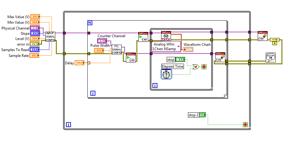
I am currently using a PCI-6251 DAQ card with a block of connection BNC-2120. I have a VI (one that is attached to this topic) that will essentially be an analog input signal and produce digital impulses from the output of the meter to each instant trigger. I am also able to define a series of delay values such that the delay will update automatically each at intervals specified by the user or when you press the stop button. I wonder if there is anyway to change this program as the time-out value will change every instant release. So, for example, in the first trigger a pulse is produced 0 second delay, then immediately when the next instant relaxation is reached, a push will occur with a 0.1 second delay, etc... And I want that the series of the time-out values to keep looping. I tried to use my current VI, with time to stop at each iteration to be less than half of the period, so theoretically it should go to the next delay value in the next instant trigger. Then I tried to put a certain time-loop around it to keep the job going, but it doesn't seem to work. I've attached a screenshot of my attempt, please let me know if this is possible, thank you! To see what each part of the VI in the screenshot, please see the screws attached, thank you!
P.S. for the VI that is attached, the analog input signal is 281Hz, the pulse width is 2.5% of the period and the delay is in the stages of T/20.
No worries,
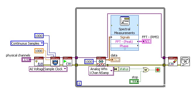
Please see the attached block diagram image. It is important to wire terminal on the Read.VI DAQmx acquire in a constant to the number ofsamples. This will force this function to wait until many samples are available in the buffer. In my example, you will get 1000 samples per second (because my rate is 1 kHz). and these 1000 were submitted directly to the FFT. What happened for example of you, it is only because you have not specified the number of samples to read, it is by default (-1), which means that the DAQmx Read.vi will pull all the data that is available in the buffer at the time. So if you had only 2 samples in the buffer that your FFT will have only two samples on average and as a result it will fail. Try this and it should help!
-
USB-6211: analog input signal affecting another of the same map AI
Hello
I use the DAQ-nor-6211 map and DAQmx features to read a hammer and a signal of the accelerometer and then use other LabView functions to make the FFT of these analog input signals. However, it seems that the analog inputs where the hammer and the accelerometer are connected generate a kind of noise or influence in other entries of this data that is not connected to any other sensor acquisition board.
I've had different experiences in order to check if the problem is with reading the card: put the accelerometer and hit the dog in another table where the DAQ card table was located (to avoid the vibrations on the map and a possible noise), ai1 entry was logged on the differential mode on the dog and the ai4 of entry is connected to the output (z axis) of the accelerometer. The other 2 ai2 and ai3, entries that can also be read by my LabView program, are open (i. e., any other sensor is connected to the card). When the structure where the accelerometer is located is struck by the hammer, the signal of ai2 ("x axis" seen in the first attached document) has a curve (on the time domain) which initialize almost at the same time that the hammer and the a3 of entry has a weak signal, but with the swing as well as the signal of ai4. The document "hammer ai1 + z_axis connected_ _x_axis disconnected ai2 + y_axis ai3 ai4" images that I captured the chart created in LabView. On these graphs, it is possible to check on the FFT the ai3 signal and ai4 has the same behavior (with different intensities), and enlarged figure of time domain image, we can see that the signal of ai2 increase almost at the same time of the signal of the hammer (ai1). The signal picked up by the sensors are probably creating a sort of noise on open entries ai2 and ai3.
Another experiment was conducted to check if the signal from a single entry that may affect the signal read from each other near the entrances: the DAQmx task Create channel had a physical channel has changed: ai3 entry has been modified by ai7 (maintain the same connection mode: differential), and the results are visible on the second attached document. In the graphs obtained in this experiment, it seems that the entrance of the hammer (ai1) affects the signal of input ai2 and ai7, which are not connected. And the ai4 signal does not seem to influence the other inputs, because he has a different curve on the graph of the FFT.
The same experiment was conducted using the CSR connection (change threads and create the DAQmx Channel Configuration), but the results were the same as those found using differential connection.
Finally, if the output of the accelerometer is connected on the ai2, the signal of the other open entries ai4 and ai7 seem to be affected by the signal of the accelerometer on ai2 (last document attached).
Could you tell me if the problem I encounter is caused by the DAQ card with this information that I gave to you? And if the answer is Yes, do you know if there is a way to avoid this noise create in one entry on the other hand, it please?
Thank you
Maybe Ghosting or crosstalk? Just an idea.
Maybe you are looking for
-
Settings for automatic coloring of the information of the film selected in iTunes?
Before the 12.5.1 updated, iTunes displays the film selected using an algorithm to color text information and text background to complement the art of the poster for the film, and I was wondering if there was a way to get this behavior after the "upd
-
I wanted to know if there is a compatible 802.11ac wireless that would work in my laptop card? DV7-4165dx XH105UA #ABA Thank you Ken
-
Satellite Pro 2100 and new hard drive
Hello I saw on another post that L0nestar has installed a Western Digital WD2500BEVE (250 GB, 5400 RPM) in a Pro 2100.The question I have is what the interface is SATA or EIDE? The original drive indicates it is a SATA interface, but the WD2500BEVE i
-
How is it that a phone that is less than one year not ics? Why do you have at & t eol this phone?
-
Windows Vista GeForce 8600 M GS graphic card does not. HOWTO fix?
I really need help. Just a couple of days my HP Pavilion dv9000 series laptop was working perfectly and now the graphics do not work. Any time I try to watch a video anywhere like on youtube, my screen fills with colorful random horizontal lines. I h