Medium-sized dynamic data analog input read DAQmx read
Hi, I'm new to labview. Is there an easy way to index using the dynamics of data returned by a readout DAQmx x samples to calculate a moving average? My thought was to read the analog input for X samples pump with the data in another loop through the data, but I can't quite understand how index using the returned data set to extract the measurement value double returned for each sample.
Any ideas on that?
Thank you...
If you get a type of waveform data, why did you ask on dynamic data? No, of course not would you use the conversion of dynamic data on a waveform.
If you want only one channel, then your DAQmx Read could be changed to 1Chan NSamp. If your channel list only has one channel, you will get a table 1 d with a single element that can be indexed. To get the average of a waveform use the statistical function with the waveform. You use the average Point by Point, and not the average function that has a table for an entry.
Make sure you always have context-sensitive help on. You can avoid many of these rookie mistakes simple.
Tags: NI Hardware
Similar Questions
-
Frequency measurement of analog input using DAQmx C APIs on SMU-6341 map
Hello
I use Linux DAQmx and attempt to measure the frequency of analog input using the map DAQ SMU-6341.
There is an ANSI-C frequency measurement example:
/ usr/local/natinst/nidaqmx/examples/ansi_c/Analog_In/Measure_Frequency/Cont_Freq-Int_Clk-SCXI1126
However, the call to DAQmxCreateAIFreqVoltageChan results in the following error:
DAQmx error: selected physical channel does not support the type of measure required by the virtual channel you create.
Create a channel to a type of measure that is supported by the physical channel, or select a physical channel that supports the type of measure.
Property: DAQmx_AI_MeasType
Required value: DAQmx_Val_Freq_Voltage
Possible values: DAQmx_Val_Current, DAQmx_Val_Resistance, DAQmx_Val_Strain_Gage, DAQmx_Val_Temp_BuiltInSensor, DAQmx_Val_Temp_RTD, DAQmx_Val_Temp_Thrmstr, DAQmx_Val_Temp_TC, DAQmx_Val_Voltage, DAQmx_Val_Voltage_CustomWithExcitationTask name: _unnamedTask<0>
State code:-200431
DAQmx does support the function of the frequency on the map 6341, or should we use examples of voltage and calculate the frequency manually?
Frequency of HAVE it is a type of channel that has been supported only on the SCXI module name of the example.
You will need to use a voltage input channel and calculate the frequency manually for your device.
-
6036E PCMCIA + DAQmx (analog input) seems to only read in blocks of 512 samples of data
Hello people,
I ask this question before I post any code or software versions etc to see if there is a simple answer.
I use a PCMCIA card 6036E to read an analog input channel (DAQmx... i. e create task, create the channel, set the altimeter (continuous samples), task, read in a programmed software loop while (ASAP)). No matter how I put my sample rate, number of samples per channel (i.e. size of buffer), or the number of samples to be read, it looks like I can get multiples of 512 samples.
Here are some samples freq (Fs), the 'number of samples to read' asked and the actual number of samples read:
FS numberOfSamplesRequested numberOfSamplesActuallyRead
200Hz 20 512
1000 1024 5000Hz
2000 2048 5000Hz
QUESTIONS RELATING TO THE:
1 is this 'normal' behavior a 6036E PCMCIA card?
2. in the case, has anyone who may have seen this problem determined the cause and how to "fix it"?
Best regards
Chris
chassan wrote:
Hello people,
QUESTIONS RELATING TO THE:
1 is this 'normal' behavior a 6036E PCMCIA card?
Sort of.
2. in the case, has anyone who may have seen this problem determined the cause and how to "fix it"?
Best regards
Chris
Systems PCI DMA is used to transfer
the data, daqmx and receive messages when the number of samples are
acquis. Now on PC-card that does not work and the data is transferred
When the edge buffer is full (after 2 k of data) to 2 channels
10 Hz, it can take some time.
There is a work-around, there is a property where you can set the transfer mechanism (I have not daqmx on this PC), or the daqmx polling mechanism. Try these.Found a document KB.
Tone
-
How to synchronize the analog input and the output of two different USB data acquisition boards
Hi all
I have two tips very different USB NI USB 6008 case, which I use to acquire the data (analog input) and a USB of NI 9263 is a output analog only site I use to route a signal (in this case a square pulse). The reason why I use the outputs analog 6008 is because I need to deliver negative tension and need the full +/-10 v range.
Looking at similar positions, I'm pretty sure that I can't use an external trigger or a common clock, I also tried to use the timed synchronization of the structures but no cigar.
I'm including a quick vi I whipped showing how the jitters because of the lack of synchronization signal. The OD of the 9263 connects to AI in the 6008 in this example.
I talked to a specialist in the phone and tols me that's not possible.

-
reading of the analog inputs with RPC
Hello
Because LabVIEW can not handle this (in VI; the value that you have saved the excel file has not been the same, that I saw during the measurement...) This confused me for a long time
 ), I want to write a C++ program (IDE: Dev - C++) which can read & record 2 analog inputs of the NI USB-6009 box. For this, I looked for an example of National Instruments and I found a little. But my problem is that I can't even use any example, because it has always held a mistake, after that I have compiled and started.
The error once the task has been created and has the :-200220 error number with the description "device identifier is invalid. But I do think that its invalid, because it's the xP example
I must say that I am new in programming C++, which means I could have a rookie mistake. And I couldn't find documentation or something for the NOR-DAQmx library.
Someone has similar problems with DAQmx and C++ and know how to fix? I don't really know what I can do now without a working example or documentations...
Hi Mario
It's the same thing. You didn't just save all of the data:
Please take a look at my comments in the attached VI.
Christian
-
Full scale PXI - 6254 DAQmx Analog Input
Hello
I use PXI - 6254 Board to read the analog inputs. Configured channels using DAQmx create Channel.vi with sub parameters.
In the configuration: CSR
Min: 0
Max: 10
Units: Volt
I read the channel using DAQmx Read U16 2D with the sample of 1. I expected below the values.
data of 0 v = 0
10 volts = 65535 data
but it gives 10 volts = 31544 data. Please let me know why.
If I set up the channels with the settings below:
In the configuration: CSR
Min:-10
Max: 10
Units: Volt
He always reads the same values (data 0 v = 0, 10 volts = 31544).
Please let me know, how I can get 10 volts = 65535
Thank you
Hi LVTestek,
The PXI-6254 is not an interval 0 to 10 V input V. The specification of 625 x OR lists the available input ranges:
Entry level of ± 10 V, ± 5 V, ±2 V, ± 1 V, ±0, 5 V, ±0, 2 V, ±0, 1 V...
When you set Min = Max 0 = 10, DAQmx chooses the smaller input range that allows to measure signals between 0 V and 10 V without clipping. On the PXI-6254, the smaller input range that meets this criterion is the range of ± 10 V, where - 10 V corresponds to-32768 0 V corresponds to 0 and 10 V corresponds to 32767.
However, there is an additional complication: ranges entry on M Series devices are slightly wider to accommodate the software calibration. Otherwise, gain of a device could reduce the scope of actual entry, and offset error would move the ends of the effective input range. If the [-10 V...] 10 v] range on your PXI-6254 could be more like [-10.3 V...] 10.4 V]. 10 V is actually to 31544, rather than 32767. On another PXI-6254, 10 V could correspond to a different value of gross / scaleless and 31539 31552.
Another side effect of calibration of the software, is that the data returned by the flavours 'raw' and 'no' to the VI DAQmx Read are benchmarked. The KB explains further: is raw data DAQmx calibrated or chipped?
If you can modify your application to use one of the flavors "on the scale" (F64) VI DAQmx read, which should save a lot of effort. If not, could you explain why your program requires readings without scales/bullies? The right approach depends on the requirements. For example, if you want to save the data in a file and you need to reduce the file size by using raw data / scaleless, configuration DAQmx to save data directly a TDMS file can meet your needs. If you update an older application to work with DAQmx and M Series, a different approach may be more appropriate.
Brad
-
read the multiple analog inputs at the same time
Hi all
I use USB-6001 and want to develop an application to multiple tasks in C++. I try to read several analog inputs at the same time, but got some errors. To put it simply, I copy one of the sample code to read in analog data in a channel, and then turn it into function. Then I call this function to thread with the names of different poles (for example Dev1/ai0, Dev1/ai1) and I come across this error:
"The specified source is reserved. The operation can not be specified such complete"code of State-50103
I have search the forums, this may be because I use the hardware timing in this function, and this material timing cannot be used simultaneously by multiple tasks. I may have to put all the lines, I want to read in a single task (such as Dev1 / ai0:1). This way I can read two lines at the same time. However, when I try this, I encounter another error:
Status code "buffer is too small to contain the data read" - 200299
So here is my question, what should I do if I don't want to read the multiple analog inputs at the same time? Is the thing that hard time cannot be used by several true task? If I have to read several lines to a single task, how to set the settings?
-
How to write constantly to analog output and read from analog inputs
Hi all -
I had a question about writing continuously to analog output reading simultaneously an analog input.
It's my first time to post a message to the community, so please let me know if I made mistakes.
I use Labview 2011 with a NEITHER-DAQ USB 6215.
I'm looking to generate a waveform and write it continuously in an analog output. It is then connected to an entry on the acquisition of data, where I am trying to sample the analog signal. (I realize, there is a system of trivial, but I'm hoping to build on it once I have run).
The task of reading from the analog input works fine, as I tested it in several other cases. I have a problem writing to the analog output.
For this task, I tried to follow the "Gen Cont Wfm Clck Int' VI to generate the wave form and start the task. I then try to write to the output of the analog timed loop. However, it does not seem to transmit a signal and doesn't give me any errors.
I have attached the VI but also a screenshot.
Please let me know if anyone has any ideas. I would really appreciate the help!
Thank you
Peter Borgstrom
We will review your tasks one at a time. First of all, the task of generation/Analog output Waveform. Generate you a waveform (I'm unsure of your VI if it is a fixed waveform or not) and send it to a defined output function to produce a waveform continuously, using N-channel and samples of N (where you set not these previously). You should not put this inside has timed loop, as the DAQ hardware has its own clock - if you simply put it in a while loop (with a stop to break out of the loop), the loop will call the function for the first points of N, wait until all N have been taken out, then call it again to another N points (up to what you press Stop).
Now, suppose that you have the output connected to a load voltage (say a decent resistance). You can wire the input terminals of your A/D converter through the same load and set up a similar analog input loop, running in parallel (i.e. in its own independent of the OD loop, while loop). You pourriez start together (with, say, a merged error since the initialization code line loops HAVE and AO become lines of error in "loops of sampling" described above), but you might want to delay loop (a little) the AI so that the OD has a chance to set the voltage before the bed.
I hope this helps.
BS
-
Good day to all,
I use NEITHER-7350, LAbview 8.5 and try to measure the voltage from a power source.
Is there a screw that read the analog inputs. I can't open the examples.
Thank you
Have you watched the DAQmx? Create a virtual channel, start the task and read the value.
http://zone.NI.com/DevZone/CDA/tut/p/ID/5370
-
How to merge and write analog inputs, and export data to a tdms file?
I have a vi who writes analog inputs in tdms files. I also want to write the analog output signals, which are 2d table entries in the same PDM file with additional columns representing the analog output signals. How can I get this feature?
Ashaironix wrote:
Hey Crossrulz,
So you're saying that writing two files tdms with entries as HAVE and AO, will write everything in a file single tdms AOs and Ais?
N ° you write in the same file, just different GROUPS. TDMS is a hierarchical data format. You have the file, group, channel. Waveform data will actually in the channel data. But you can have metadata on any level. So, I do a group I and a group of the AO.
-
Analog inputs measures with NI6229 using the DAQmx driver
Hello
I have four different analog inputs connected to ai0 to HW 6220 ai3. I read these values with a single task, all 4 channels assigned to this task. When ai0 reads 7V, I see 0.8 V ai1 too, but I expect to be measured 0V. If I just assign ai1 to the task and measure all 4 channels, then I measured 0V as expected (although ai1 contains 7V, I just don't measure it).
Another comment 'funny', is that if I change the order in which I add channels to the task, measurement errors are different.
However, when measured with a multimeter 4-channel show tensions as expected.
Given that my calling task is can not block, I call the function
DAQmxReadAnalogF64 with timeout = 0 and numSampsPerChan = 1.
Any help is appreciated.
Thank you
Kind regards
Deepa
Deepa,
Thanks for the code snippet.
When you call DAQmxReadAnalogF64 the first time and you set a value of timeout of 0, there is a chance that the acquisition is not yet initialized. This is the expected behavior and should not be a problem. If the timeout error died at the first call, you might ignore it or set a different expiration time for the first call only. In all cases, you should drop the first value and start with the second value.
Jochen
-
Need to read a 30, 1.5 a analog input using a NOR-9205
Problem: I need to read two analog inputs with good resolution using a C-Series card. The two beaches of signal are 0-30 V @ 1.5 and 0-5 V (not sure of the current). I need to be able to read the signal 5V with a precision of mV (or 16-bit resolution).
I looked at the module-9221, which works very well with the 30V, signal, but does not have enough resolution for the 5V signal. The 9221 is 12 bits on the beach of 60V.
I looked at the NOR-9205, which works very well with the 5V signal, but it cannot process the higher V 60 signal.
If a voltage divider circuit comes to mind, but has anyone found a good solution to this (other than to get both modules)?
Well, the current should not question. The entrance of the analog device (ideally) should draw no current and everything running on the source will cross the UUT.
A 4:1 voltage divider should evolve the signal to 9205 AI as long as you do not violate the absolute maximum voltage between a pin of the device and the Earth.
-
How to read the analog inputs of one Board of R for (PXI-7851R) series
You can guide me please with the steps for reading of the analog inputs of a series a. card I use as the target fpga PXI-7851R.
Have you looked at the examples provided with LabVIEW? There are examples showing how to read the analog inputs.
-
Read the counter timeout in synchronized to count-analog input
Ciao, Giovanni.
The two tasks are run in parallel so there is no guarantee which task starts first. I suspect that when you are away from the counter samples, it is because the task of analog input before starting the task of counter. In this case, the task of counter would be ready to accept examples of clock and may be missing some edges of the clock at the time wherever he is started.
One way to solve the problem would be to use the wires of the error in order to ensure the time started the task of counter in front of the task of analog input. You can also use a sequence structure to do that.
The counter is sampled on each edge of the sample clock HAVE no matter what you set the 'rate' of entry to the. When you use an "external" clock (external to the task that is), the driver uses just the entry rate to set some default parameters (size of buffer for example).
If you have any questions, feel free to ask!
Best regards
-
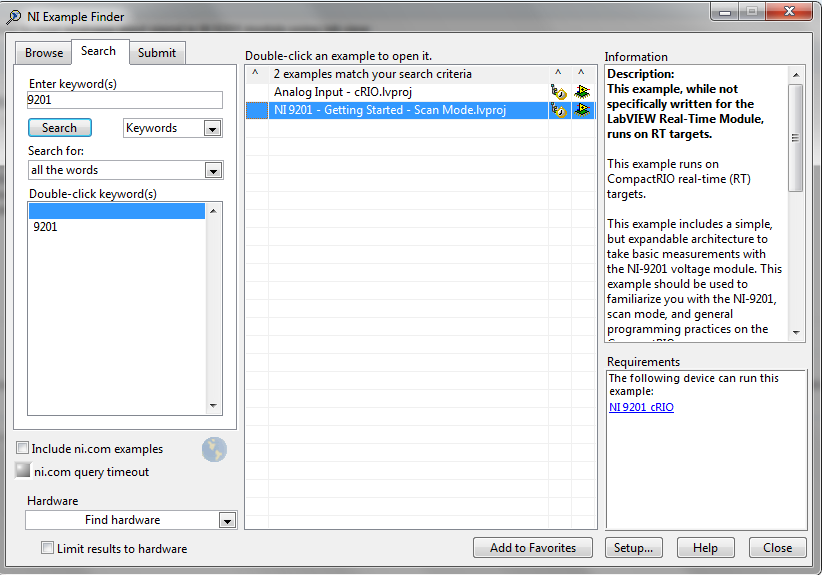
How to read the NI 9201 Module lab mode analog input signal
Hi all
IAM using the module Crio-9012 real-time controller
ND iam using NOR-9201 for entry and exit of NI9263 for
I have configures cRIO 9012 on my Pc
But how I'll take analog input using the module NOR-9201
Thank you
TC
Hello
I recommend you take a look at the following examples in the example Finder LabVIEW. If you go to help--> find examples, you will see this window. Just search 9201 and you will see 2 examples:
I hope this helps!

Maybe you are looking for
-
Satellite U500 - 1 1 - Ram and HDD upgrade suggestions
I am owner of a satellite U500 1 1 which has 4 GB of ram memory and hard drive HDD. There are suggestions, to upgrade up to 8 GB ram and SSD hard drive. Thanks in advance for any answers.
-
Slow down the TV Tuner on my Qosmio F10
HelloI have a Qosmio F10 which comes with a tv tuner. The software that comes with it to watch TV is Inter WinDVR 5 video. But the problem is that this software seems to be very slow, changing channels takes like 5 seconds to go from one channel to t
-
Cannot open the PDM file with excel 2016
Hey guys,. I have Office 2016, LV 2015 and (I checked my "TDM Excel Add-in" file) the Excel Add-in 2015 of CT. I have attached a picture of what I get when I try to open the PDM file with excel. So, I found something strange. I checked active supplem
-
Use FTP fails, disconnect remote desktop, XP Pro
Windows XP Professional SP3, Application in VB6 using WinInet FTP, remote access from Windows 7 to XP pro. I had problems with one of my VB tasks. It has worked fine for years and now is a failure because it downloads only the partial files FTP. It
-
Hey,. Is there a way to make the bubbles SMS/BBM/Talk style without having to implement again myself? I would have preferred a seamless integration for my application, rather than a custom style. Thank you Daniel