6255 sampling rate causes the dc offset
I see a dc offset in the measures of analog input I select different sampling frequencies.
I have USB-6255 (mass termination) multifunction data acquisition and I use measurement and Automation Explorer to put in place my entries.
My raw analog input is-0, 6250 volts dc, I have set up a task that uses 4 differential channels with no custom scale.
I have defined the scope of the input signal to +/-0 .8v for you sure I get good resolution.
Acquisition mode is continuous, samples of read is 1 k and I play with the order of 10kS/s rates 50kS/s.
While this task runs in the MAX, I can put my cursor in the rate field and use the top and down arrow keys to change the sampling frequency. As I do, I can see the light changes reported as much as 150 MV rate from one to the other.
It is a significant change when the total time of entry is lower to +/-1v.
The direction of movement is independent of the increase or decrease of the sampling frequency.
For example,.
23kS/s, the declared value is - 0.540v,
24kS/s, she moves to-0.620v.
25kS/s, she moves to-0.690v.
26kS/s, she moves back to-0665v.
27kS/s, she moves back to-0.625v.
and 28kS/s, she moves to - 0.535v.
At first, I thought that the sampling change made a change of the input impedance and change the load on my source, however, all the time, my dc signal source remained at the - 0.625v (as measured with a multimeter fluke at the connection point to data acquisition).
Why this is happening and what can I do about it? I want to give my users the ability to choose their desired sampling frequency.
My guess is that I need to add an amplifier to fixed gain with a gain of 5 to 10 to make the input signal to use the maximum of the analog input level (+ / 10v).
I use MAX version 5.0.0f1
Thanks for any help,
Tobin
Hi Tobin,
What do you use to generate the signal-. 625 volt? If you are using a switching power supply, you can experience aliasing where the power supply is turned on and stop.
In addition, are see you the same tensions at the same sampling rate? See you always - .540v to 23kS/s or vary over time?
Finally, you have a second 6255 you can try to replicate this on? It could be that the unit is defective.
N
Tags: NI Hardware
Similar Questions
-
Different sampling rate with the same connector AIO, Labview FPGA
Hello
I use LV 2009 with the new Toolbox FPGA and an NI PXI 7854R. I acquire an analog signal with a sampling frequency of 600kS / s. I need as the sampling rate for the processing of the data, but I also need the signal sampled with a much smaller, variable sampling frequency to a FFT.
I've attached a picture to clarify, in a simple example, I'm looking for.
I tried with the structure case only take each ' iht iteration, but did not get the expected results.
Does anyone have another idea how to solve my problem? Of the, "Resampling" express VI in the funtion FPGA palette does not help me.
Thanks in advance,
Concerning
Hello
the connector for the analog input is a "shared resource", so you should he alone in your FPGA Code.
Find attached an example that shows how to perform this task of analysis.
Concerning
Ulrich
AE OR-CER
-
With audio files (in particular the WAV), Audio sampling frequency and the size of the Audio sample are not the choices available in the list of details with Vista. In earlier versions of Windows (2000 and XP) they were both selectable as details. Is it possible to get these will appear under Vista?
Vista - related audio details available:
Album
Album artist
Bit depth
Bitrate
Duration
Kind
Year2000 / XP - audio related details are available:
The album title
Artist
Audio sampling rate
Audio sample size
Bitrate
Kind
Title
The track number
YearFWIW, sampling frequencies are discussed in the Help window and how to (below).
Reference: http://windowshelp.microsoft.com/Windows/en-US/Help/53adb4c7-d538-42f8-bb13-917379922afe1033.mspx
Thank you!
For the third part of the applications that perform many tasks, I usually discover www.tucows.com and www.download.com. They have a wide variety of programs, and the trick is to put in the correct search terms to find what you are looking for. Make sure you that your selection is compatible with Windows Vista and at tucows, try to pick one with 4 or 5 cows because they are the highest rated.
Good luck! Lorien - a - MCSE/MCSA/network + / A +.
-
determination of the sampling rate and the frequency waveform data record
Hello
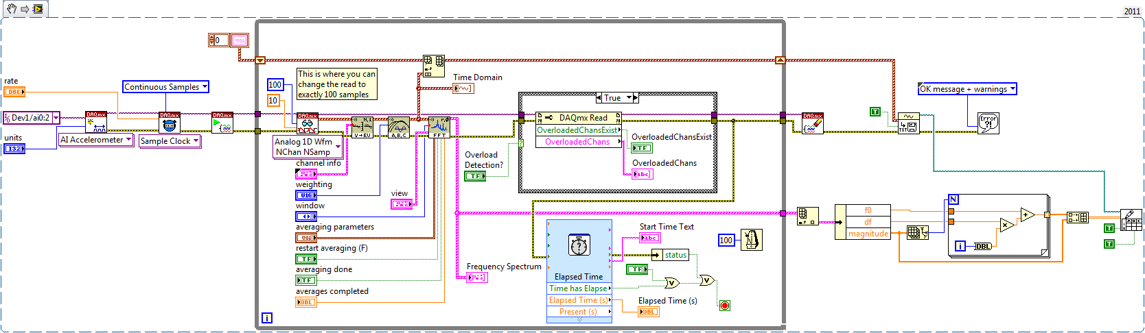
I write a simple program that collect data from a triaxial accelerometer input, convert it to a frequency spectrum, and then save the time domain and the frequency of the waveforms in an external file separated. I don't understand how to set the sampling frequency, however. On the DAQ Assistant, I updated the acquisition mode "Samples continues" and read samples is 2 k, which corresponds to the total number of data points that are collected. How can I program sampling for awhile, it 30 seconds, for example? Wouldn't be better to set up a trigger, as it will continue to collect data up to what I told it to stop?
I also want to save waveform data in a separate file that can be easily seen by other computers that have not installed Labview. I have currently the program put in place to convert a text string of the waveform of the time domain and then save it in a text file or a spreadsheet. It works fine, but I would also like to record the frequency wave, which is a different type of data. How can I do this or is there a better way?
My program is attached. Thanks for your help!
Here's how you can use the shift register to build the table, and also where you can choose to play exactly 100 samples per while the loop iteration.
Brian
-
Getting the error «for input and output sample rate does not match...» »
I am trying to create an audio file, but when I click on the record button I get this error:
«The sampling rate of the audio output devices and audio don't match.» Audio cannot be recorded until this problem is corrected.
Use the appropriate operating system or control panel of audio device to adjust the sampling frequency of the output devices and audio entries to use the same settings. »
I have the preferences set to use operating system controls and it seems to work because when I change in the Win 7 Pro CP it adjusts at the hearing.
So I do not know which need to be addressed. I use the video card as the source and not the speakers thus mean the output must be la carte too?
Please help, I'm confused.
Thanks for your time!
Got an answer to a previous question asking how to record and thought, this could be useful for others.
It takes a Windows setting and a setting of the hearing.
You will need to go into your settings from Windows recording devices - if you see a speaker in the lower right of your screen, right-click on it and choose recording devices. Find your audio input source, select Properties, go to advanced. You should see a drop down menu with options for the quality and frequency of sampling, mono/stereo. In general, you'll want to 44.1 kHz for audio; 48 Hz for the video.
At the hearing, go to Edition/Preferences/Audio Hardware and select the same frequency of sampling for output. I went through the same question a few months ago, and it worked for me. Good luck!
-
sample rate real vs min sampling rate
I'm sure it's an obvious answer, but here goes.
I have a USB-5132 ' scope and using niScope horizontal configuration Timing.vi I put, among other things, the minimum sampling rate. In my case, I chose 20 MHz, which of course gives a sampling of 50 ns period.
I use niScope reading (poly) .vi with the WDT variant to read waveform data. I noticed something very strange - waveform limit testing throw error 1802 "signals have a dt of different values '-if I put a waveform components unclusterizer Get on the wire of waveform and looked at the value of dt of the wave." He told me that my dt is 40 ns, which of course is of 25 MHz. I also plead for only 2000 samples.
So what causes this shift? Why the digitizer does not accept everything just my desired sampling frequency?
Austin Walton wrote:
Andy,
The setting of minimum sampling frequency is the frequency at which digitized
the samples are stored, expressed in samples per second. This setting is rounded
up to and including the next legal collection that supports your device. Ownership of the actual sampling rate calculates the actual sample used for the acquisition rate.Unless you specify another source of the clock, the digitizer uses an internal oscillator as clock source. For the 5132, this oscillator is clocked at 50 Mhz. When using the oscillator internal as the sample, the digitizer clock source can use versions split to the bottom of this clock, for certain sampling frequencies are not possible.
-
reading of the sampling frequency of the NI9862
Hi all
I use a DAQ chassis with modules 9205 (analog input) and 9862 (NOR-XNET CAN).
I have a program to synchronize the modules for acqustion based on the attached example. My question is how to determine the rate at which data comes the 9862?
It seems to be double the rate of the 9205 when I set the sampling rate for the 9205 to 500 Hz.
Is there a property node or a method that I can use to find the rate? I looked in the manual, and it gives no information.
Thank you
Griff
griff32,
Baud rate XNET CAN occur in your database. You can also check using a property node. In the example, in the XNET Session property node, you can develop, select the Interface > baud rate. You can do a right click on it and change it to read and son in an indicator.
Alternatively, you can write to this property node to replace the transmission speed in the database. Baud rate must be compatible with the speed of your network. It also has a max of 1 mbit/s. If you want both to acquire the same amount of data, I would recommend changes in the rate of the analog input task or samples to read through.
-
Hello
What is the sample rate max 5154 PCI for two channel inputs? The manual States the 2GS/s is for one channel only. So, am I not able to get a bandwidth of 1 GHz for the simultaneous measurement of two channels? Thank you!
Hi gbhaha,
First of all, TIS mode up to 20 GECH. / s using an ADC, while your real time sampling uses two converters a/n at the same time to a single channel. Take a look at these diagrams that I linked in my first post for more details on this architects.
About the difference in the bandwidth between the 5153 and 5154 - the 5153 has 500 MHz of bandwidth in its circuits, even when acquiring at faster sampling rates. The 5154 1 GHz of bandwidth, this is why it is more expensive.
Kind regards
-
. VI filtering IIR and response: response of Butterworth filter size depends on sampling rate - why?
Hi people,
I'm not an expert in the design of the filter, only a person in applying them, so please can someone help me with an explanation?
I need to filter signals very infrequent using a buttherwoth filter 2. or 3. order of the bandpass 0.1 to 10 Hz.
Very relevant amplitudes are BELOW 1 Hz, often less than 0.5 Hz, but there is as well the amplitudes beyond 5 Hz to observe.
It's fixed and prescribed for the application.
However, the sampling rate of the measuring system is not prescribed. It may be between say between 30 and 2000 Hz. Depends on the question of whether the same set of data is used for analysis of the higher up to 1000 Hz frequencies on the same measure or this is not done by the user and he chooses a lower sampling rate to reduce the size of files, especially when measuring for longer periods of several weeks.
To compare the response amplitude of 2nd and 3rd order filter, I used the example of IIR filtering .vi and response:
I was very surprised when I found that the response of greatness is considerably influenced by the SAMPLING RATE I say the signal generator in this example vi.
Can you please tell me why - and especially why the filter of order 3 will be worse for the parts of low frequency below 1 Hz signal. Told me of people experienced with filters that the 3rd oder will less distort the amplitudes which does nothing for my the frequencies below 1 Hz.
In the attached png you see 4 screenshots for 2 or 3 command and sampling rate of 300 or 1000 Hz to show you the answers of variable magnitude without opening labview.
THANK YOU very much for your ANSWERS!
Chris
Hello Cameron and thanks for my lenses of compensation.
I can now proudly present the solution of my problem.
It seems to be purely a problem of the visualistion information filters through the cluster of the scale.
After looking in the front panel of the IIR, I suddenly noticed that the "df" of the pole size is changing with the Fs of the input signal.
For a Fs to 30 Hz, the "df" is 0.03 Hz so you see the curve of the filter with more points, see png.
For a Fs 300 Hz "df" is 0.3 Hz, so the curve is larger with only 3 points between 0 and 1 Hz.
For a 1 kHz Fs the df is 0,976 Hz, so there is no point in the graph between 0 and 1 Hz.
It's strange that for constant Fs, df of this cluster NOT reduced with the increase in the number of samples, as it does in an FFT.
However, I hope now the filter used now for the curves obtained with the proposed Lynn way and the response of greatness from the filter information fit together.
Thank you for your support.
Merry Christmas and a happy new year to all.
Chris
-
Analog LabVIEW myRIO data sampling rate
I have been using the myRIO to acquire the audio input from a microphone.
In LabView, I use the VI Express Analog Input to get the data.
I wanted to know if there was a way to increase the sampling rate of the data of this VI, or any what VI to whom?Hi ykhali,
Try to put the VI in a timed loop and set the loop to your sampling rate.
Kind regards
-
Hello
I tried to understand how the 'number of samples' and 'rate' controls affect the frequency of sampling for the DAQ hardware. For example, say I want to acquire data from a sensor of pressure at a frequency of 10 Hz intuitively, I would think everything I do is on the desired sampling frequency, in this case 10 Hz control the 'frequency', try this, I know that's not true. I read that 'number of samples' affects the sample rate by setting a buffer value that must be reached before the VI will process the acquired data. So I also tried to set the "number of samples" to 1 and "rate" at 10, thinking this would have led to a sampling frequency of 10 Hz, and again, it is not. The only way I know to control the sampling frequency is using the wait function (ms), but then I always get buffer overflow errors.
Can somone if you please explain to me the error in my thought process and also tell me the best way to control the sampling frequency? Is attached a simple VI, I am using to measure my actual sample rate and compare it to the sampling frequency that I am trying to achieve.
The VI use the DAQ assistant to acquire data of pressure, inserts data into a table, and measure the size of the array. I'm then by dividing the size of the array by the elapsed time in seconds for the sample/s (I'm also dividing the number of iterations of the loop by seconds and using it as a comparison). I compare this value to my entries for the 'number of samples' and controls 'speed' in order to give a sense of the role they play in sampling rate. The VI also allows to choose to use the wait function (ms), as well, using this function is the only way I can control the actual sampling frequency, but then I always get buffer overflow errors. Any information would be helpful, thanks!
What is the device that you are using? My guess is that whatever you have, it does not allow such a slow pace and is failing at its minimum.
-
Audition 3.0 how to disable ASIO and the default Sample Rate recording?
Hi people,
New here, but I hope someone can help me with a few questions, I'll have with Audition 3.
Firstly, some background questions.
I use hearing parallel to a broadcast audio broadcast program called SpotOn,
This software requires that I run the sound card, a RME Madiface XT in 48 k mode, and that all the outputs that it uses are defined as WDM Windows so that the windows kernel mixer can control them.
This means that when I use the hearing at the same time, I have to configure it to use the "Audition 3.0 Windows Audio" driver to stop him from taking control of the sound card directly and change setting which prevent SpotOn to see its output.
The problems I encounter are that hearing itself seems to randomly change mode in the edit window ASIO driver, I suspect that this happens when I import audio data from a key which is from 44.1 to modify for use in SpotOn. This often seems to not only make the outputs of the card its invisible to the windows kernel mixer but also change the sampling frequency of 44.1 sound card and stops work SpotOn.
The second question I have is that the sampling frequency of default record when I record in edit mode is always 44.1 and if used it again change the map sound 44.1 and causes the same problems, I'd be very keen to know how to change this default to be 48 k if possible.
Then.
What I ultimatly looking is...
1. a way to disable the ASIO drivers in hearing so that it is not only this option is available, and cannot use the Audition 3.0 Windows Sound Drivers.
2. a way to make the sampling rate 48 k to stop people choosing 44.1 mistakenly when saving default record.
Any help or advice that anyone can give would be much appreciated.
Thanks in advance for your comments
What other pilots ASIO sees your installation of 3 AA? If it's the Madiface one and you use only WDM drivers you can just uninstall the ASIO RME driver?
-
DMM (NI 4070), how to correctly set AC Freq (bandwidth) by the sampling rate
using a NI4070 multimeter and I see the max connection is 300 kHz by respect it. But I don't understand how to set the min and max, acFrequency according to the sampling frequency or speed reading.
6 1/2 digits resolution, the speed can vary from 0.25 s/s to 100 s/s and this range corresponds to a lower end on the connection (minimum acFreq) from 1 Hz to 400 Hz.
(Q1a) - is the playback speed, controlled by the minimum setting of IviDmm_ConfigureACBandwidth? or vice versa?
Otherwise, I do not see how to control the rate of reading or the sampling frequency. IviDmm_ConfigureMeasurement only allows you to control the range and resolution.
(Q1b) - is there a way to directly control the sample rate (digitizer) or playback speed (dmm)?
(T2) - the upper limit of the bandwidth of AC always seems to be at 300 kHz... is there still a reason to reduce this maximum value?
(T3) - Finally, unlike the traditional niDmm function, the resolution via the IVI configuration should be passed as absolute value; does directly when number of digits and the beach? For example if I want to 6 1/2 digit to 300V range, I guess that by the specifications that the resolution should be set at 0.001 V... followign, if I want 5 1/2 digits to 1V range, the resolution should be set to 0.00001 V?
Hi Rjohnson,
I'll try to answer your questions as best as I can:
Q1A. The ConfigurACBandwidth function is used by the driver OR DMM to calculate the good aperautre for the measure. So yes, by adjusting your minimum frequency, you will affect your reading speed.
Q1B. Your reading rate will depend largely on your measuring cycle. To get a fast measuring cycle, there are a few things that you can adjust. You can programmatically control your time aperature, as well as your time to settle.
Q2. I can't find a reason to change. This parameter is only used for error-checking and verifies that the value of
This setting is less than the maximum frequency of the device.Q2B. I think what you say is right, but I'll need to check on that - I'll let know you as soon as.
Hope that helps. "" "I would recommend checking the explanation of the Cycle of the DMM measurement in DMM help' devices ' NI 4070" DMM Measuments "DMM measurement Cycle.
Take care!!
-
Why my sample rate does not match the output of timestamps in the waveform?
Hello
I run a simple application to read the data of two pressure sensors output signals 0 - 5V to a NI9215 module, and one connected to the 9237 module load cell. They are housed in the 9172 chassis.
I am new to DAQ and labview, and I find it difficult to reconcile the sampling frequency that I put in the sample clock and the apparent rate data (according to the timestamps in the waveform that I output to a text file). For example, if I ask 100 Hz rate (and 10 samples to read), the data appear to sample at 1612,9 Hz. If I ask the sampling frequency of 1000 Hz, outgoing data is 1612,9 Hz to 20 kHz, the data came out to 25 kHz.
Can someone tell me to trust the timestamps given in the waveform that is written in the text file, and if there is a way to check this? If this timestamp is correct, how can I force the application of sample data at the requested speed?
As a secondary issue, in my attached VI, you can see that I have an attached to an array of construction shift register. I can't understand how to initialize the array outside of the loop as it clears the table before the next time I run the program. Any advice?
My VI is attached.
Thank you
Claire.
Hi Marc, thanks for the quick response and the right explanation. It's all much more clear now.
Have a great weekend,
Claire.
-
Hello!
I'm in the quest to replace some aging PCI-5640R. I am currently using as a portable-Journal data solution, mounted in a Magma Expresscard to PCI box with a laptop. As a reference of the time, I use a Symmetricom XLi.
The equipment is dependent on the sampling finished a set of samples once a trigger signal goes high and also receive antenna azimuth information using two lines PFI more. The signal is sampled at IF, 30 MHz, and the signal is less than 5 MHz bandwidth.
Now, I started watching the Ettus X 301 with a GPS OCXO and MXI-express interface which should be the same as the USRP-295xR NI. It is available as device NI RIO with three different front ends, unfortunately, none of them work at 30 MHz.
Q-1: Ettus has the front-end 'BasicRX', but it is only considered compatible with LabVIEW driver and not necessarily with the RIO. Is the front-end BasicRX usable with the USRP - 295XR RIO and MXI-interface with LabVIEW FPGA? Should I just avoid trying tune the nonexistent LO? As long as he gives me data, I can live with some error messages during the Setup...
It's the best solution for me, but if it is absolutely impossible, I have a few questions:
Q-2: information on the front end are really rare in the pages Web OR both Ettus, but the WBX is listed up to 50 MHz frequency, to have a filter of low pass of bandwidth of 40 MHz to I and Q. This should mean a total of 80 MHz of bandwidth with I and combined Q,-40 to 40 MHz. Why did the bandwidth to Web pages as OR listed being "40 MHz bandwidth in real time", if the low pass filter of the WBX is 40 MHz in I and Q? Not the band total bandwidth or 80 MHz?
Q-3: assuming a bandwidth-40 to 40 MHz: could I put the WBX LO at 50 MHz, be tuned to the frequencies from 30 MHz to 20 MHz signal,-20 MHz and use a bandpass filter to the FPGA to extract the new signals and remove all other signals?
Q 4: I tried to start a FPGA project in LabVIEW and add the x 301/294xR/295xR as a target. Data clock is locked to 120 MHz, which I guess means he will receive no data to 120MS/s IQ? The x 301 Ettus is listed as provide data of the ADC to the FPGA at a rate of 200 ms/s, could someone explain to me why, OR USRP RIO expects only database 120MS/s?
Hi Idar,
Yes, you should be able to put the basics on your X 310/USRP RIO and use LabVIEW FPGA to receive 120 MECH. / s of the DACs. The example I posted is in fact not for the precompiled file bit. The example I posted is for LabVIEW FPGA, which allows you to add the IP address for the FPGA. There is a sample project that comes with LabVIEW FPGA which is the recommended starting point to build your FPGA application. The sample project has all the configuration set up as well as broadcast continuously and pads/FIFOs in the FPGA and examples for synchronization. There are comments in the code example that show where he must add your own blocks of property intellectual as a filter and decimater you mentioned. The PDF I posted shows what changes you must make to this sample project using the Remora Basic/LF.
I would like to know if I'm not explaining this clearly, or if you have any questions, I'd be happy to help you!


Maybe you are looking for
-
Unknown devices on Satellite M70-340
Hey,.My problem started when I updated my Toshiba Satellite model: M70-340 with Windows Xp professional. Most of the drivers have been detected by windows, except for those:(1) mass storage controller(2) network controller(3) PCI modem I was wonderin
-
Directory services cannot start SBS2003 lsass.exe error?
Hi all I have a SBS 2003 server who gave a customer who seems not to start windows.It gives 0xc000007a error code (Directory Services cannot start because the specified procedure could not be found).After finally the local Windows password reset, I a
-
I have a router Linksys E2500. It seems to block a website (evernote.com). I can't access this site from any of the computers / devices in our home, they are connected by ethernet or wireless. However, when I move to another network, I can connect t
-
Installation of Windows 7 - can not find HARD drive
Hello. I am trying to install Windows 7 Pro. Setup does not find my HARD disk. I tried loading sata drivers - did not help. I have run the hard drive test and had no error. What can I do My laptop HP G62-b40sw
-
BlackBerry smartphones can not set the homepage on the Bold 9700, non editable field
When I followed the instructions to reset the home page of the browser to the URL of my choice, I'm stuck. It says choose Options, Configuration of the browser, and then type a new URL in the Home Page field. Seems pretty easy. But this field is n