Analog LabVIEW myRIO data sampling rate
I have been using the myRIO to acquire the audio input from a microphone.
In LabView, I use the VI Express Analog Input to get the data.
I wanted to know if there was a way to increase the sampling rate of the data of this VI, or any what VI to whom?
Hi ykhali,
Try to put the VI in a timed loop and set the loop to your sampling rate.
Kind regards
Tags: NI Software
Similar Questions
-
I'm new to myRIO and use it to measure sine wave (0V to 5V) of up to 10 Hz 20 KHz. I also quickly transformed of Fourier (FFT) of the signal measured in real time.
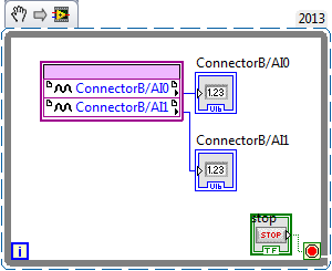
Sideways FPGA of things, I try to keep things pretty simple, just read 2 channels of AI (connector B: AI0 and AI1), therefore potentially able to read each HAVE 250 kech. / s (as the unit has a capacity of 500kS/s). Does that mean this program gets a two analog inputs data exactly every 4 microsecond? If this is not the case, how can I make sure that the data is acquired through a fixed sampling rate?
I realized that we can add to the FFT in FPGA function, but I wanted to manipulte the acquired data of analog inputs before it is sent to the FFT, which I don't know how to do now. Can someone explain me how do the arithmetic data (muliplication, division and so) on the acquired data and analog inputs to reducde the 12-bit resolution 10-bit to program FPGAS.
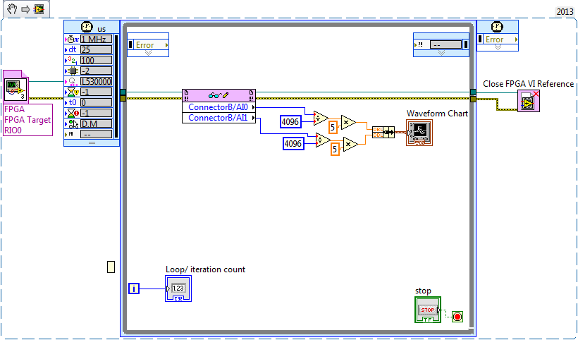
Later, I created a myRIO program to read analog data 2 FPGA program which continues to turn in timed loop. In the program myRIO, the timed loop is configured to 1 MHz clock source type by a delay of 25 microseconds.
This configuration means that the loop runs exactly every 25 microsecond?
When I set up the less than 10 micro second time, myRIO has stopped working. Why is it so?
Is it because myRIO cannot run as fast as FPGA?
It is advisable to make the FFT of myRIO side analog data or FPGA?
When I tried to do FFT using the power spectrum of myRIO side, he asked for waveform data. What I acquire is data analog. How can I convert in waveform data?
If I read in the forum for help, I couldn't have the full answer to my doubts
Discussions at the Forum I did reference:
A lot of good questions here, I will try to answer as much as I can so as to offer a bit of advice.
First of all, if you are looking to acquire data at a very specific rate on the FPGA, you'll want to use the Timer VI. You are also going to use a FIFO of DMA to transfer data of FPGA in real time. A node read-write using as you do now means you'll run out of samples, or read the sample even several times. The link below is a very good tutorial on how to do what I described above.
http://www.NI.com/Tutorial/4534/en/
Later, I created a myRIO program to read analog data 2 FPGA program which continues to turn in timed loop. In the program myRIO, the timed loop is configured to 1 MHz clock source type by a delay of 25 microseconds.
This configuration means that the loop runs exactly every 25 microsecond?
When I set up the less than 10 micro second time, myRIO has stopped working. Why is it so?
Is it because myRIO cannot run as fast as FPGA?
In general, you should not run a timed loop much faster than 1 kHz. Using timed inside loop knots, you can monitor the real rate of loop during execution to see if f you meet your needs of the moment.
The portion of your myRIO RT is slower than an FPGA in the sense where it cannot manage the rates of lines 40 MHz (he makes up for it by being able to work with much better pictures) and it is important to remember that it is just a computer. The advantage of a real-time operating system, is that you have more control on the Scheduler, not that he is faster (less jitter, not faster code). There is more good reading below.
http://www.NI.com/white-paper/3938/en/
It is advisable to make the FFT of myRIO side analog data or FPGA?
When I tried to do FFT using the power spectrum of myRIO side, he asked for waveform data. What I acquire is data analog. How can I convert in waveform data?
I would say that it is generally advisable to treat your FFT on the side FPGA as long as you have the resources available, but for many applications probably little matter ultimately.
-
Hi talented engineers OR,.
I use PXI 5015, measurement studio and make acuqisition of data sampling rate 40 MHz. The command
niScope_ConfigureHorizontalTiming (vi0 40000000, 40, 50, 1, VI_TRUE)
is used to set the sampling frequency. However, when we check the signal of sampling, it is 60 MHz rather than 40 MHz. same thing happened when it is set at 50 Mhz. The actual sampling frequency is always 60 MHz. But when we created the frequency goes low to 20 MHz or 10 MHz, it works fine. We use an external 10 MHz reference clock, and I'm sure that the PLL is locked. We are a State control.
Everyone comes up with the same problem? Please let know me if you need more information about it. Thanks in advance.
Sincerely,
Bin
Hi Ben,
Unfortunately, the only way you can use a 40 MHz sampling frequency is if you import it into 1 PFI. The ditch down the method that we use with our advice on sample clock gives you only the integer values 1 and more. 60 MHz is your next best option.
Kind regards
-
acquisition of data with different sampling rates high
I have a few questions on the use of the OMB-DAQ-3005 with different sampling rates high.
For our application, we have 8 analog inputs. Which two are a quick response and should be sampled frequently. We have an encoder quadrature (CPR 1000 running at 1800 rpm). We plan to sample X 4 encoder. For the analog inputs for the quick response, we want to trigger a sample of each pulse or each a few pulses, thus creating a timestamp with the position of the encoder with respect to position index as well as two fast analog inputs. We have data correlating the analog inputs with the position of the encoder. Other analog inputs, we want to measure relatively slowly (for example once every 5 dry or similar).
How can I go on the configuration of the two (or more) sampling rates different wherein I can taste entered at different frequencies? Also, is there a way to reset the encoder count after outbreak of the index as I have the position of the encoder with respect to the index?
Maybe you'll find someone here who uses the OMB-DAQ-3005, but this forum is really more designed for LabVIEW programming issues.
I've never used the OMB-DAQ-3005, but out of curiosity, I took a glance at the Manual of OMB-DAQ-3005. The answer to both your questions are:
1. you cannot run a hardware DQA Multiplex (like this one) at independent rates by channel.
2. the OMB-DAQ-3005 supports an Index Z feature to reset the counter - look for documentation on how to configure any software interface you are using. If you get stuck, you can try to discover media appropriate for instrument channel.
Best regards
-
Sampling rate - too much data points
Hello community,
I use a sensor signal strength of pressure on DAQmx labview through 2014. My rate from the hardware synchronization function is 50 KHz. The samples per channel of timing and read screws are the same set to 5 Khz when the channels are a continuous sampling. The problem I'm having is that when I run labview for a few seconds, say 5 seconds, I'm half million points of data. I tried to run for 10 seconds and points were more than a million where it is difficult to analyze. I think that the vi generates too much data points and the buffer is large. Am I wrong? Can you please help me solve this problem?
Kind regards
Mike
You are now ready to learn a little of the power of LabVIEW and data flow programming. LabVIEW is an inherently parallel language - two loops can run independently and in parallel, allowing you to make time-sensitive (such as sampling data) and a lot of time (such as data logging and tracing) at the same time, using queues to pass data between the loops and ensure the buffering required.
If you open LabVIEW and click on the file menu in the toolbar, and then select new... (the points are important!), you will be able to create new ones (VI) from the model. Choose a Framework, Design Patterns, producer/consumer Design Pattern (data). It's what you want to do.
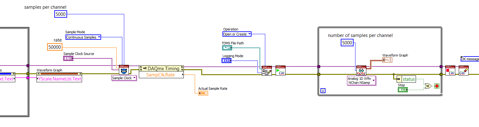
You basically set up a "pure DAQ Acquisition Loop" (without logging TDMS) as producer, creation of 5000-element arrays of data every tenth of a second (if you are sampling at 50 kHz). You create a queue of data outside the loop of producer whose elements are an array of 1 D of waveforms (the output of your Read DAQmx) and instead to send the data to a waveform graph, you put it in the queue.
You are under this loop, a parallel loop that gets the same queue and remove items. This loop will be sitting idle (no time taking CPU) until the data is queued. He then it takes away the poster and registers (logs) in a PDM file. Either way, you should open the TDMS file before entering this loop (consumer), write to the file inside the loop and close the file when the loop exits. Study the example of the VI, you create with the model and see how it works.
The beauty of this is that you can certainly 'keep up' with the writing of the data points in a TDMS file to 50 kHz. You might not be able to display all the points, but there is nothing to prevent you from data processing (by, say, decimating or "block average" it) to a more 'user-friendly' display (your eyes ' sees' a 50 KHz signal?) -you have a set of 100 msec prior to the next package arrives in the queue. Also note that the loop of producer probably takes very little time CPU - most of the time the material is waiting for its clock to 'tick', collection of points in a buffer, then transferring to the loop.
Now you can have your cake and the computer display, too.
Bob Schor
-
Save the high sampling rate data
Hello!
I use NI PXI-4462. (204.8kS, input analog 4 / s sampling frequency)
I want to collect data from "load" (channel 1) and "acceleration sensor" (2nd, 3rd, 4th channel).
I also want to save data to a text file.
So I do a front pannel and block diagram. You can see in the attached file.
The program works well in a low sampling rate.
However, when I put up to 204800 s/s sample rate, the program gives me "error-200279".»
I don't know what means this error, and I know why this happened in the high sampling rate.
I want to know how I can fix it.
Is there any problem in my diagram?
Is it possible to save high sampling rate data?
I really want to samplling more than 200000 s/s rate.
I would appreciate if you can help me.
Thank you.
NH,
You have provided excellent documentation. So what has happened is that the amount of time it takes to run the other portion of the loop results in a number of samples to be taken is greater than the size of the buffer you provided (I don't know exactly what it is, but it will happen at high frequencies of sampling high) resulting in samples are crushed. You might be best served in this case to take a loop of producer-consumer - have the loop you have acquire the data but then have an additional loop that processes the data in parallel with the acquisition. The data would be shipped from the producer to the consumer via a queue. However, a caveat is that, if you have a queue that is infinitely deep and you start to fall behind, you will find at the sampling frequency, you specify that you will begin to use more and more memory. In this case, you will need to find a way to optimise your calculations or allow acquisition with loss.
I hope this helps. Matt
-
Different sampling rate with the same connector AIO, Labview FPGA
Hello
I use LV 2009 with the new Toolbox FPGA and an NI PXI 7854R. I acquire an analog signal with a sampling frequency of 600kS / s. I need as the sampling rate for the processing of the data, but I also need the signal sampled with a much smaller, variable sampling frequency to a FFT.
I've attached a picture to clarify, in a simple example, I'm looking for.
I tried with the structure case only take each ' iht iteration, but did not get the expected results.
Does anyone have another idea how to solve my problem? Of the, "Resampling" express VI in the funtion FPGA palette does not help me.
Thanks in advance,
Concerning
Hello
the connector for the analog input is a "shared resource", so you should he alone in your FPGA Code.
Find attached an example that shows how to perform this task of analysis.
Concerning
Ulrich
AE OR-CER
-
Currently, I am trying to log readings of DC voltage with an AA battery in an ASCII using LabVIEW 2009 of SingalExpress file and the USB-4065 digital multimeter (DMM). I have two stages:
(1) acquisition of Signal > voltage DC using DMM
-resolution 4.5 with 3.333333E the value-5 sampling period
2) save in ASCII
-The value to add to the file, delete the file after each race
Faster reading, I can get is a data point written in the ASCII file every eighth of a second.
Furthermore, I am new and software OR LabVIEW, the LabVIEW SignalExpress software I have is only for evaluation as it was included in the CD of the driver for the USB 4065 DMM.
- Max (30 000 samples per second) sampling rate is only achievable by a LabVIEW VI?
- Don't I have the wrong settings for DMM step?
- Is it because I haven't activated SignalExpress and am only using the evaluation version?
Thanks in advance for any help!

Hello Lukos,
You are assuming that you need access to lower level functions in order to obtain the higher sampling rates. In order to get these speeds, we need to disable some settings that are not accessible via Signal Express. You can create a VI and then use a step VI call in Signal Express to stay in the same environment.
Kind regards
-Travis E
-
I am using a cDAQ 9172 with modules NI 9219, NI 9264 and three NI 9211. I'm looking to acquire signals out of the acquisition of data within a loop under continuous sampling. My program works fine if I set the number of samples to read 1-2 Hz, but I need to go faster than that. If I change the sampling rate, the loop is executed at this speed but sensors still read only in samples at 2 Hz and then duplicating over and over again. I was wondering if it was possible to read on 1 sample at the time of the acquisition of data at a faster rate. I know that the frequency of sampling on the sensors and data acquisition are much higher than that. 1 sample at the time of the Board of Directors has the limitatioins of being only able to run at 2 Hz? Please let me know
Thank you
Craig
Hi Craig,.
I don't know exactly what you describe. Are you feeding the DAQmx Read output in an express VI? Or are you using the express VI DAQ Assistant for the analog input task?
If you use the DAQ Assistant, you can set the ADC synchronization mode without changing your code:

If not, use the 'Active channels (if subset)' property to control the subset of channels on which your VI defines AI. ADCTimingMode.
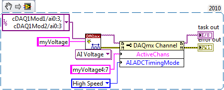
For example, the following code snippet creates 8 virtual channels named myVoltage0 by myVoltage7 and sets HAVE them. ADCTimingMode on myVoltage4 of virtual channels through myVoltage7. These are in the cDAQ1Mod2/ai0 physical channels via cDAQ1Mod2/ai3:
If you leave off of the entry "name" on the string to create VI, then the virtual channel names are the same as the names of physical channel, so it's the equivalent:
And by the way, a right-click on the property and selecting "create > Constant ' context menu saves you from having to hardcode a number like 14712.
Brad
-
6255 sampling rate causes the dc offset
I see a dc offset in the measures of analog input I select different sampling frequencies.
I have USB-6255 (mass termination) multifunction data acquisition and I use measurement and Automation Explorer to put in place my entries.
My raw analog input is-0, 6250 volts dc, I have set up a task that uses 4 differential channels with no custom scale.
I have defined the scope of the input signal to +/-0 .8v for you sure I get good resolution.
Acquisition mode is continuous, samples of read is 1 k and I play with the order of 10kS/s rates 50kS/s.
While this task runs in the MAX, I can put my cursor in the rate field and use the top and down arrow keys to change the sampling frequency. As I do, I can see the light changes reported as much as 150 MV rate from one to the other.
It is a significant change when the total time of entry is lower to +/-1v.
The direction of movement is independent of the increase or decrease of the sampling frequency.
For example,.
23kS/s, the declared value is - 0.540v,
24kS/s, she moves to-0.620v.
25kS/s, she moves to-0.690v.
26kS/s, she moves back to-0665v.
27kS/s, she moves back to-0.625v.
and 28kS/s, she moves to - 0.535v.
At first, I thought that the sampling change made a change of the input impedance and change the load on my source, however, all the time, my dc signal source remained at the - 0.625v (as measured with a multimeter fluke at the connection point to data acquisition).
Why this is happening and what can I do about it? I want to give my users the ability to choose their desired sampling frequency.
My guess is that I need to add an amplifier to fixed gain with a gain of 5 to 10 to make the input signal to use the maximum of the analog input level (+ / 10v).
I use MAX version 5.0.0f1
Thanks for any help,
Tobin
Hi Tobin,
What do you use to generate the signal-. 625 volt? If you are using a switching power supply, you can experience aliasing where the power supply is turned on and stop.
In addition, are see you the same tensions at the same sampling rate? See you always - .540v to 23kS/s or vary over time?
Finally, you have a second 6255 you can try to replicate this on? It could be that the unit is defective.
N
-
fast sampling rate question...
Hello
I use USB-6009 and max sampling rate is about 48 K samples/s according to
the specification...
Question 1.
48 K samples/s means... only when you receive 1 analog input?
If I have 2 analog inputs then forge would be just half of the 48K?
Question 2.
using the daq assistant.
I would like to get about 50 samples between 10ms
If I do the math I get 5 K samples/s, which is enough for me
However, I played with samples to read and throughout the day, the sampling rate,
do not get this rate... (I'm outputing in file with LVM)
I searched on the sampling frequency, and people here said
samples read and sample rate do not havea correlation...
but I see clearly that they are relevant. When I change a setting
I get a different number of acquisition... I do N smaples.
Please help:)
Q1. Yes, except that the switching of channels takes awhile so the net price per channel is slightly less than half the rate of single channel. The USB-6009 specification document does not indicate what is the switching time. You should be able to get 5 kHz on both channels. 20 kHz might be close to the upper limit, but that's just a guess.
Q2. The DAQ Assistant is often not the best choice for maximum performance. I do not have the DAQ Assistant, so I can't be more specific. If you get the data as an array of DBL, rather than dynamic data type, it can be recorded directly, without conversion. The other thing that can make a big difference is a loop two architecture of producer/consumer. This allows the acquisition of data and save it to the file to run it at different speeds so that each can be optimized separately. If you are trying to acquire 50 ms of data at a time and then, he writes to the file, you write to the file twenty times per second. The first time, the operating system must reallocate some file space or do something else what delays write the file, your timing loop is disrupted.
Lynn
-
. VI filtering IIR and response: response of Butterworth filter size depends on sampling rate - why?
Hi people,
I'm not an expert in the design of the filter, only a person in applying them, so please can someone help me with an explanation?
I need to filter signals very infrequent using a buttherwoth filter 2. or 3. order of the bandpass 0.1 to 10 Hz.
Very relevant amplitudes are BELOW 1 Hz, often less than 0.5 Hz, but there is as well the amplitudes beyond 5 Hz to observe.
It's fixed and prescribed for the application.
However, the sampling rate of the measuring system is not prescribed. It may be between say between 30 and 2000 Hz. Depends on the question of whether the same set of data is used for analysis of the higher up to 1000 Hz frequencies on the same measure or this is not done by the user and he chooses a lower sampling rate to reduce the size of files, especially when measuring for longer periods of several weeks.
To compare the response amplitude of 2nd and 3rd order filter, I used the example of IIR filtering .vi and response:
I was very surprised when I found that the response of greatness is considerably influenced by the SAMPLING RATE I say the signal generator in this example vi.
Can you please tell me why - and especially why the filter of order 3 will be worse for the parts of low frequency below 1 Hz signal. Told me of people experienced with filters that the 3rd oder will less distort the amplitudes which does nothing for my the frequencies below 1 Hz.
In the attached png you see 4 screenshots for 2 or 3 command and sampling rate of 300 or 1000 Hz to show you the answers of variable magnitude without opening labview.
THANK YOU very much for your ANSWERS!
Chris
Hello Cameron and thanks for my lenses of compensation.
I can now proudly present the solution of my problem.
It seems to be purely a problem of the visualistion information filters through the cluster of the scale.
After looking in the front panel of the IIR, I suddenly noticed that the "df" of the pole size is changing with the Fs of the input signal.
For a Fs to 30 Hz, the "df" is 0.03 Hz so you see the curve of the filter with more points, see png.
For a Fs 300 Hz "df" is 0.3 Hz, so the curve is larger with only 3 points between 0 and 1 Hz.
For a 1 kHz Fs the df is 0,976 Hz, so there is no point in the graph between 0 and 1 Hz.
It's strange that for constant Fs, df of this cluster NOT reduced with the increase in the number of samples, as it does in an FFT.
However, I hope now the filter used now for the curves obtained with the proposed Lynn way and the response of greatness from the filter information fit together.
Thank you for your support.
Merry Christmas and a happy new year to all.
Chris
-
Hello
I'm looking at possible solutions for data acquisition. I use 4 or 5 entries analog and two digital inputs. During the analogue entered most of them will not need sampling extremely quick rate except for one who needs the least 100ks/s. I noticed solutions cost-effective have overalls sampling rate (eg. 250 ksps / s) which extends on all channels. For these products, such that the NOR-9205 compactRIO module, is possible to distribute unevenly sampling rate between channels (ie. could I give up 100ks/s for a single channel and spread the 150ks/s rest between the remaining channels in use)? Thanks in advance for any help,
Adam
Hello Adam,.
To answer your question on the sharing of the sampling rate, it is not possible to have a single module different sampling frequencies, as described in this KB: here (http://forums.ni.com/t5/Multifunction-DAQ/Aggregate-sampling-rate-and-Multichannel-Scanning-Rate/td-....)
In the case of the 9205 this module multiplexes between all channels (32 cases set up in single ended mode or 16 in differential) this means that the sampling rate of 250 kech. / s matches total on all channels.
If you are using the differential mode then the samples per second on each channel will be 250 kech. / s divided by 16, IE 15KS/sec. However if you only specify 4 channels max sampling frequency will be 250 kech. / s divided by 4, IE 62.5 kech. / s.
One way around this is to use 2 x 9205 in one of our new CompactDAQ chassis, which has 3 engines of timing to HAVE. This allows to set different timings in 3 different modules. What is described in this KB: here (http://digital.ni.com/public.nsf/allkb/E7036C1870F6605686257528007F7A72)
I'm sorry of this reply took so long, and I hope the above information helps.
Please do not hesitate to answer questions.
If you want I could get one of our technical sales engineers to give you a call to discuss further with you data acquisition system?
Kind regards
-
Specified sample rate clock works do not
I hope that I was right to post on this forum. I have a problem that I had not previously in the acquisition of data on a chassis 9172 cDAQ using a 9234 for 2 analog inputs and a 9219 for four thermocouple inputs. The 9219 is obviously not ideal as it has a rate relatively low sample (and I have a 9213 on the way), so I'll have to use to HAVE. ADCTimingMode to isolate channels on this module for "high speed" mode if I can get an adequate sampling for my load. The question that arises is that no matter what I do to specify a sample rate, the actual sampling rate ends up being 1651,61 Hz, higher than the features of the 9219, if I get an error. I tried to use the DAQmx property node to set the calendar and the clock sampling VI but neither work. The only source that I can choose is on board, but when I check the source used is cDAQ1Mod1/AI/SampleClock, even if I get an error when I try to provide as a source of sample VI clock.
As it is, my VI runs despite this error and seems to produce accurate data, but the original problem is with long testing I will have unnecessarily large data sets unless I start to decimate my other data, and the secondary problem, it's that I can't get the program to run when I try to incorporate my task of counter. In this case, the error ends the execution and he acquires no data.
I have attached my VI under the task of counter (I'm on 8.5 and have the coming upgrade as well), but also an image of a simplified version of the VI only try to specify the settings of a channel of AI. I get the same result with it. I'm a bit of a loss here because I've never had this problem before, and it seems that there is something beyond rudimentary that I'm missing, so I would really appreciate any help anyone could provide. Thanks in advance.
-
On the NI PCI-6221 fast sampling rate question
Hi I was wondering if someone can answer a question of sampling rate on this card to PCI-6221 (http://sine.ni.com/nips/cds/view/p/lang/en/nid/14132).
Especially if I wanted to transmit simultaneously (analog output) and data acquisition (analog input), what is the sample rate max I could use. Kind regards.
Since the 6221 is multiplexing the analog input, your question for I / simultaneous ao is possible for one channel of the only. If your "simlutaneously" can include delays (e.g., 100us), you may be able to work with several AI channels as well...
HAVE the multiplexes, workable sample rate given that the total sample (250 kHz) frequency divided by the number of channels that you use. AO is faster than HAVE it, so it does not reduce this number.
hope this helps,
Norbert


Maybe you are looking for
-
How to set the text bigger? Help.
Want more text on the screen. Besides that I printed everything has been very itsy bitsy... much smaller than on the screen.
-
I want to change my master password in Firefox, but it does not accept my only current
Firefox won't accept my current master password so that I can change
-
Orthographic corrector OSX will not forget incorrectly entered word
So, I'm still relatively new to OSX but get in the swing of things being a power user. Anywho a type a message in Chrome and went to automatic correction of a word misspelled, low and here is because I clicked a little to fast he gets add'd to my dic
-
BlackBerry calculator Z10 - converter
I have my Z10 for about a year and after 3 or 4 large software updates, that there is still no converter basic ml to oz. These units of measure are as around us such as kg and lb, km and mi. We see ml soft drinks, bottles, cans, etc... Would it be so
-
SX80/20: registration number and directory
Hi guys,. I have deployed a solution of cloud CMR to a customer. they have little sx80 and sx20 (no other end points). This solution includes 1 cucm, exp, exp 1 e 1 c... That's all. When endpoints are for the first time or (even when we re-) they g