6289 PCI > multichannel sampling of 250 kHz?
I'm tasting nearly 250 kech. / s with the PCI-6289. Is it possible, or is an aggregate of the 500kHz listed on the spec sheet 6289 sampling rate means I am limited to 500kHz / (N # of channels). Currently I use four analog inputs and analog output in my VI and sample up to about 100 kHz.
I can attach code on request.
Thank you.
Hello Tom,
You're right, the PCI-6289 global sampling rate is 500KHz /(Number of Channels) can have 250 KHz, but then, you will be limited by two channels of GOT it, because there are 4 input channels maximum, you can enjoy is 125 KHz / channel. If you want to sample every 250 kHz channel, we have simultaneous card PCI-6143 smapling and there is also 8 channels to HAVE
See you soon
NOR-khil
Tags: NI Hardware
Similar Questions
-
Hello
What is the sample rate max 5154 PCI for two channel inputs? The manual States the 2GS/s is for one channel only. So, am I not able to get a bandwidth of 1 GHz for the simultaneous measurement of two channels? Thank you!
Hi gbhaha,
First of all, TIS mode up to 20 GECH. / s using an ADC, while your real time sampling uses two converters a/n at the same time to a single channel. Take a look at these diagrams that I linked in my first post for more details on this architects.
About the difference in the bandwidth between the 5153 and 5154 - the 5153 has 500 MHz of bandwidth in its circuits, even when acquiring at faster sampling rates. The 5154 1 GHz of bandwidth, this is why it is more expensive.
Kind regards
-
limited on PCI-6052E sampling frequency
I'm trying to measure with two channels with a PC containing a NI PCI-6052E card that is capable of 333KS/s on LabView 8.2. With two channels each channel must be able to 333KS/s / 2 = 166.5KS / s. everytime I try to set the sampling frequency above 94339 Hz I the following warning and the vi no longer works.
WARNING 200012 occurred DAQmx start Task.vi:1
Possible reasons:
Clock speed specified is greater than the maximum ADC conversion rate. ADC invaded errors are likely.If I place a similar task in the Measument and Automation Explorer and I can easily make two channels measures to 160kHz without error. Above 166kHz I start getting the same caveat (200012). The code that I use calls first DAQmx create Channel.vi, then DAQmx Timing.vi and finally DAQmx start Task.vi. Everything works fine and I did measuements, but I can't rise above 94339 Hz sampling rate even if it should be possible.
I just looked and I can't understand the issue here.
Dear Voyn,
I thank very you much for your message on our forum. If you create a task for a single channel, you can get a higher sampling rate? Are you able to reproduce the same problem with an example from the finder example? Go to hardware to go end tab selected and output-DAQmx online-online-online-online Acq Cont voltage analog measures & chart voltage-Int Clk.vi
You can select several channels as well. If it shows the same behavior; which driver DAQmx do you use?
Best regards
-
Peut PCI 6534 sample of both 32-bit output
Hi, sorry only if she's not interested.
I was with C++ and NOR-DAQmx to a generation of model externally triggered on PCI-6534. By using the following code, I was able to generate an array of 32-bit both samples:
uInt32 DataArray [Nsamples];
DAQmxErrChk (DAQmxWriteDigitalU32 (taskHandle, Nsamples, FALSE, Timeout, DAQmx_Val_GroupByScanNumber, DataArray, & written, NULL));
When I switched to NOR-DAQ, it seems that I can group all the data with space = 4, but following each function, the data type of 'piBuffer' virtue 'i16"(16-bit integer). What I have to recalculate all my data and divided into two groups?
DIG_Block_Out (iDevice, Group, piBuffer, ulCount);
If this is done, it will be able to output defined smaple of 32 bits in each clock cycle or two cycles needed?
Thank you.
Kxz,
Thanks for posting on the Forums of NOR. In my view, there are a few suggestions for this, you'll have to forgive me a bit that we do not get a lot of questions on the DAQ hardware traditional much more. I think you have a few options in your case:
(1) the DIG_Out_Prt function which can be called four times (once for each port) with a pattern you want or,
(2) you can call the DIG_Block_Out function, now the entrance of the buffer will be an entry with two tables, each of the 16 elements. You will need the size of your group as 2 (2 groups of 2 ports) or 4 (4 groups of 1 port), DIG_Block_Out writes data to the low 8 bits of the buffer [0] in the port (port 0 or 2) and the high 8 bits of buffer data [0] to the top port (port 1 or port 3) lower. If the group size is 4, DIG_Block_Out written data buffer[0] to ports 0 and 1 and the bufferdata [1] in lanes 2 and 3.
Overall, we strongly suggest to use DAQmx for your programming, but we have good documentation on all C functions in aid OR-DAQ traditional (old). You can normally find this file under start > programs > National Instruments > NOR-DAQ > traditional NOR-DAQ function reference help. This includes all the documentation for our text-based features. Thank you!
-
672PCI 6723 error when you try to generate a signal with the sample of 20 kHz clock
I have a piece of code that worked successfully on the PCI-6224 map, but when I tried to implement the same code on the card PCI-6723 I ran into problems.
Here is the code I use:
ManchConversion6723();//produces SendIt array of series of 1s/0s

// DAQmx Configure Clock
DAQmxErrChk (DAQmxCreateTask("",&taskHandleFRQ));
DAQmxErrChk (DAQmxCreateCOPulseChanFreq(taskHandleFRQ,"Dev3/ctr0","",DAQmx_Val_Hz,DAQmx_Val_Low,0,20000,0.5));
DAQmxErrChk (DAQmxCfgImplicitTiming(taskHandleFRQ,DAQmx_Val_ContSamps,72));

// DAQmx Configure Digital Output
DAQmxErrChk (DAQmxCreateTask("",&taskHandle));MessageBox("D");//vj
DAQmxErrChk (DAQmxCreateDOChan(taskHandle,"Dev3/port0/line0","",DAQmx_Val_ChanPerLine));MessageBox("E");//vj
DAQmxErrChk (DAQmxCfgSampClkTiming(taskHandle,"/Dev3/Ctr0InternalOutput",20000,DAQmx_Val_Rising,DAQmx_Val_ContSamps,72));

// DAQmx Write Code
DAQmxErrChk (DAQmxWriteDigitalLines(taskHandle,72,0,10.0,DAQmx_Val_GroupByChannel,SendIt6723,NULL,NULL));

// DAQmx Start Code
DAQmxErrChk (DAQmxStartTask(taskHandleFRQ));
DAQmxErrChk (DAQmxStartTask(taskHandle));
When I get on the DAQmxCfgSampClkTiming line, I get an error stating:
DAQmx error: measurements: request the value is not supported for this property value.
Property
 AQmx_SampTimingType
You asked: DAQmx_Val_SampClk
You can select: DAQmx_Val_OnDemand
Task name: _unnamedTask<0>
State code:-200077
I think that the problem comes from the variable of the source of the function. I'm just tring to send the data to the frequency of 20 kHz.
Any help would be greatly appreciated. Thanks in advance!
Too bad. The impression that the PCI-6723 does not contain correlated DIO channels. In other words, examples of clock cannot be linked to the DIO channels allowing the generation of digital waveforms. According to the AO Series user manual, this applies to the NI 6731/6733 only. The mistake was trying to tell me that only a single issue or receive channel has been authorized.
For this reason, I'll stick right with my card PCI-6224.
Sorry for the confusion.
-
In Matlab FIR filter for bandpass sampling and 250 to 700kHz frequency 250MSPS
Hi all
I want to design filter implemented on FPGA with a settings mentioned in the question but when I start to design it on matlab fdatool, it gives very high order filter result, when I decrease or set myself up to 10 order its impulse response is not good, as I hear it.I use high-speed ADC with the 250MSPS.
Any idea will be very appreciable.
Kind regards
UmairUmair salvation,
You can theoretically designated any filter you want in an FPGA. If you can implement the filter on a FPGA target is another story.
There is usually some limitations on an FPGA, that one must take into account:
-Number of flip flops, READ...
-Maximum fare of lines
-Number of available multipliers
It is almost impossible to tell you, if you can implement your filter on a given target FPGA. The only way to get the right answer is to try it. A filter with the command = 50 could be really large and maybee does not fit on the FPGA or does not respect the loop rate you need.
I do not use the FDATOOL, if I can't give you an answer to your second question.
Stephan
-
What is the minimum response of analog input, through DSP online, output analog time?
Hello experts!
I want to know if it is possible to get a very quick response latency (~ 1 ms) sound recording (analog input), through online registration (DSP online), the presentation of his (analog output) processing, by using the DAQmx programming codes. My system of NEITHER includes NOR SMU 8135, SMU 6358 DAQ Multifunction controller and SMU 5412 arbitrary signal generator. I also have access to the latest version of Labview (2015 Version) software.
My project is on auditory disturbances, which inovles record vocalizations, manipulating the recorded vocalziations and then present the manipulated vocalizations. My current idea of how to achieve this fact triggered output voltage after reading the input using DAQmx Read samples. DAQmx Read output is filtered online and then passed as input for the DAQmx writing for analog output. For purposes of illustration, examples of code are presented below. Note for simplisity, codes for the trigger part are not presented here. It's something to work in the future.
My question here is If the idea above should be reaching ~ 1ms delay? Or I have to rely on a totally different programming module, the FPGA? I am very new to Labview so as to NEITHER. After reading some documentation on FPGA, I realized that my current hardware is unable to do so because I do not have the FPGA signals processing equipment. Am I wrong?
Something might be important to mention, I'm tasting with network (approximately 16 microphones) microphones at very high sampling rate (250 kHz), which is technically very high speed. Natually, these records must be saved on hard drive. Here again, a single microphone is shown.
I have two concerns that my current approach could achieve my goal.
First, for the DAQmx Read function in step 2, I put the samples to be read as 1/10 of the sampling frequency. It's recommended by Labview and so necessary to avoid buffer overflow when a smaller number is used. However, my concern here associated with the latency of the answer is that it might already cause a delay of 100 ms response, i.e. the time to collect these samples before reading. Is this true?
Secondly, every interaction while the loop takes at least a few tens of milliseconds (~ 30 ms). He is originally a State 30 late?
Hey, I've never used or familiar with the hardware you have. So I can't help you there.
On the side of RT, again once I don't know about your hardware, but I used NOR myRIO 1900, where he has a personality of high specific speed for the RT where I can acquire the kHz Audio @44 and process data. Based image processing is ultimately do the treatment on a wide range of audio data you have gathered through high sampling frequency and number number of samples as permitted by latency, please check this .
I lost about 2 weeks to understand host-side does not work and another 2 weeks to understand the even side of RT does not work for online processing (real time). Then, finally now I'm working on FPGA, where the sampling rate is 250 kHz (of course shared by multiple channels).
The complex thing with FPGA is coding, please check if the filter you want is given below as labview automatically generates some codes of some filters.
Most of them will work in 1 SCTL IE if your target has 40 MHz clock algorithm will run in 25 ns. That's what I was looking for, I hope you

See you soon... !
-
On the NI PCI-6221 fast sampling rate question
Hi I was wondering if someone can answer a question of sampling rate on this card to PCI-6221 (http://sine.ni.com/nips/cds/view/p/lang/en/nid/14132).
Especially if I wanted to transmit simultaneously (analog output) and data acquisition (analog input), what is the sample rate max I could use. Kind regards.
Since the 6221 is multiplexing the analog input, your question for I / simultaneous ao is possible for one channel of the only. If your "simlutaneously" can include delays (e.g., 100us), you may be able to work with several AI channels as well...
HAVE the multiplexes, workable sample rate given that the total sample (250 kHz) frequency divided by the number of channels that you use. AO is faster than HAVE it, so it does not reduce this number.
hope this helps,
Norbert
-
High speed continuous measurement of encoder with sampling frequency of 1 kHz
I am able at all times the position of a linear encoder using a PCI-6602 counter card, and I need to know how to set up so that the counter rotating at high speed, but the data is inserted into the buffer at a frequency of 1 kHz. I am able suddenly to a hydraulic cylinder, and I am not concerned about the event recording to high frequency except to the extent where they throw off the number considerably if the equipment does not run fast enough to detect all the impulses of the encoder.
Now, I think is that the external sample clock signal control (routed internal pulse output counter) time rate whereby the equipment detects the impulses of the encoder and the rate at which it inserts data into the buffer. With a pulse 100 per inch encoder and a sampling frequency of 1 kHz, the extended final position of the cylinder is turned off by +/-0.15 inches, which is unacceptable.
I need calculate a speed of this information, so I prefer not to use software timed sampling to control this (it's more difficult programming for other reasons as well - several asynchronous measures). Any ideas on how to configure the hardware to count faster than the speed at which she inserts counties in the buffer?
OK, you're clearly on the right track here, so I will focus on some details.
1. How do you know that the +/-0.15 "differences are * measurement error rather than * error of movement? Why wouldn't be an accurate measure and a proposal which can vary slightly from the nominal value?
2. I wonder some all electric noise and defects that may produce false edges. The fact that the behavior was better by using a sampling rate limited (200 kHz) in the digital inputs may be that some of these flaws were so short that they were never captured.
I did a ton of work with the Commission to 6602 encoder and I can certainly confirm that count equipment is sensitive to the edges in a few tens of MHz. (I know its 80 MHz for edge counting, but I think I remember that it can be of the order of 20 to 40 MHz to accommodate the time of signal propagation extra of the quadrature decoding circuit).
A small point of clarification. You're talking about the speed at which the meter "works to. The value of count is a register whose value is changed completely by the circuit, * independent * of the sampling frequency. If you enjoy with material-clocked County in memory buffer or interrogation of software without buffer not a bit for circuits that increments / decrements the value of the counter register. (In other words, I am completely convinced that you would get commensurate with position end even if you took only 1 sample software-polled after the end of the move instead of sampling at 1 kHz all the way through.)
So, if the value of the counter is disabled, it is because the circuit detects producers of County of the edges that shouldn't be there. Something you can try is to set up digital debounce filter for input lines of the PFI corresponding to the encoder Source inputs and to the.
-Kevin P.
-
read data from 10 kHz - 250 MB using tiara
Hello
I'm using labview, I do data by connecting to a sampling of 10 kHz to the task for the event, this file processed by the TDM file format, that will be generated a file per day. almost, I'll get 250 MB of file size, my question is it possible to read all the data of.. tiara?
tell me how many points can be read at the same time...?
need of documentation on the DIAdem, which is going to be really help to me
You keep doing that...
Did you do a Google search on "data maximum Diadem?
That's what it is.
http://forums.NI.com/NI/board/message?board.ID=60&thread.ID=10574
First try... and if you stuck then ask.
-
That means 'samples to read' really means
Hi all
I use a capture of data PCI-6259 now card to read data from multiple channels. However, I don't really understand the "sample to read" node in "DAQmx read.vi.
In my opinion, if I use the DAQ to sample multiple channels, this "sample to read" would be the number of samples per channel. But I don't know if sampling is at the same time or not? If not, how do simultaneous samples for different channels? According to the user mannual, data acquisition must support a simultaneous sample of channels of the difference, or I was wrong?
Kind regards
Rui
There are three parameters that control the time of an acquisition in DAQmx:
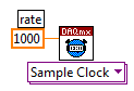
Sampling frequency
This control hurries samples are taken. This is specified with respect to the samples per second.
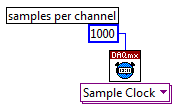
Samples per channel
For a finite acquisition, it is the total number of samples that will purchase your program. For a continuous acquisition, it is just used to help determine the size of the buffer.
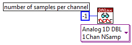
To read samples
It is a setting on the DAQmx Read VI. This allows to determine how many samples per channel is returned whenever VI Read is called. The value '-1' returns all samples that are available. If the specified number of samples are not available with the VI Read is called, reading VI hangs until the samples are available, or until the time which is connected to the terminal "timeout" runs.
Thus, for example, if we have an application with the following parameters:
Samples rate = 1000 s/s
Samples per channel = 5000
Samples to read = 100
Then the application will gather 5000 total samples at a rate of 1000 samples per second. The total acquisition will therefore 5 seconds.
We will need to call playback VI 50 times, because whenever we call the VI, it is up to 100 samples available.
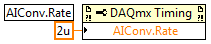
Inter channel time-out is controlled by the property of the clock to convert frequency I. The smallest value, for it can be programmed is the sampling rate overall maximum reverse for your motherboard. The default rate is 10 to allow for extra time, unless your sampling frequency is greater than 100 kech. / s, in which case, we use the smallest possible value.
So, for example, my PCI-6289 has a sampling rate overall maximum of 500 kech. / s (as indicated by the specifications). My inter channel a minimum period is so opposite of 500 kHz, or 2 uS.
You can set the clock frequency to convert HAVE using the DAQmx Timing property node:
I hope that clarifies things!
-
I use an analog input on a PCI-6224 and are having problems with the clock source
I use an analog input on a PCI-6224 and are having problems with the clock source. I'm trying samples of 16 different analog inputs very quickly. I have the sample mode: Timed Single Point material. The rate, that I am running is the maximum (250 kHz (15625Hz per channel)). I left the default clock source and trying to taste several times. The analogue input works for a short time (2-3 seconds) and then everything stops. I'm doing something wrong or is there something I'm missing? Any advice would be great.
That's how you samples using the sample clock clock. If you see a delay then something is wrong with how you track/data visualization.
Single point NI the hardware is for PID control with a real-time operating system.
-
Sampling Multiple channels of unique cDAQ Module
Hi all
I am currently researching the use of cDAQ for a system of analysis of oil, especially the module OR 9201 for voltage GOT.
We have 6 entries SE located in the voltage/current ratings, although they all need different sampling frequencies. It is my understanding that the module is capable of 500 kHz, which will be split between entries.
The sampling frequency should divided equally? Or could I for example send a 250 kHz channel and split the rest between the other 5. Synchronous between devices is not necessary.
Many thanks in advance,
Peter
Peter,
See my replies to each ball:
- Am I correct in saying that I could taste each module to a different sample rate? Yes
- If I taste the 9201 to 500kHz/6ch, will I have an effective sampling frequency of ~ 83kHz on a given channel? Yes
-
Sampling frequency of adjustment for the analog output of sine
Hello
I tried to do something very simple: using an analog output card PCI 6221 to produce a frequency 50 Hz sine curve. For this I used a Vi to create a curve sinus and different screws DAQmx. But I have trouble understanding the principle of virtual channel and I think I do an error of adjustment of the sampling frequency and number of samples: once for the vi, second time sine "DAQmx - synchronization. Can I use the same values for both of these screws?
On my oscilloscope, with frequency = 50 Hz and the sampling frequency = 1 kHz, I get a null signal. Then according to two values, I'm differently evaluated signals. For example, with f = 1 Hz and sr = 10 kHz, a frequency 0.7 Hz sinus.
Make sure that the start for the analog input task occurs after the analog output. By plugging in the wrong thread to an analogue output start task first, and then to the start task, you guarantee that the AI cannot start until after the startup of the AO.
-
I read a sine wave using a data acquisition with a sampling frequency of 250 Hz. Once I acquire the signal, I get the component signal Y and multiply it by a factor inside a matlab script. I use the wave build function to retrieve the waeform and display it. If I put the component dt of my function to build in 0.01 waveform, this means that the signal is sampled at 100 Hz?
navinavi wrote:
If I put the component dt of my function to build in 0.01 waveform, this means that the signal is sampled at 100 Hz?
Not exactly. You are just lying to the display, which gives it something which has been sampled at 250 Hz and claiming that it was sampled at 100 Hz. If you filter on it or whatever it is in the frequency domain, everything will be far away.


Maybe you are looking for
-
How to install Vista on my Satellite L300-1F8 (PSLBGE)?
Hello guys. I have some problems with my laptop. First of all, certain details so that you know exactly what I'm working with: Laptop: Toshiba Satellite L300-1F8 PSLBGEOPERATING SYSTEM: Windows Vista Home Premium Edition I had problems with several d
-
Using Droid Turbo as a TV remote control
Did someone using their Droid Turbo as a remote control for their TV? If so, what App do you use, and how does it work? Thank you
-
Invalid access to memory location
Dear all good your time I convert a labview 5.1.1 to 2008 (by convert forum) program and run it. before that, I install this 'http://www.keithley.com/support/keidoc_searchresult?keyword=2400&item_type=Software+Driver'. I was faced with this error: "e
-
ventilatieproblemen, you warm worden, en zwart scherm als gevolg
Ventilation problem, becomes too hot and after 5 min black screen
-
Security - identity of Web Site - owner (this website does not provide ownership information)
Hello! I have a website (www.lundbeckconsulting.no) with a valid SSL certificate, but Firefox says "this website does not provide information on property. Then. How can I provide property information?