waveform sampling
I read a sine wave using a data acquisition with a sampling frequency of 250 Hz. Once I acquire the signal, I get the component signal Y and multiply it by a factor inside a matlab script. I use the wave build function to retrieve the waeform and display it. If I put the component dt of my function to build in 0.01 waveform, this means that the signal is sampled at 100 Hz?
navinavi wrote:
If I put the component dt of my function to build in 0.01 waveform, this means that the signal is sampled at 100 Hz?
Not exactly. You are just lying to the display, which gives it something which has been sampled at 250 Hz and claiming that it was sampled at 100 Hz. If you filter on it or whatever it is in the frequency domain, everything will be far away.
Tags: NI Hardware
Similar Questions
-
What is the difference between waveform data and common digital data? Whenever I have do analog data acquisition, the Board always wonder if I want to put the data acquired as a waveform or DBL type. For a specific data source, there is large difference for the two choices? If I chose to acquire waveform data, how to set the sampling frequency? I mean what I will get in a "waveform sample? Will it be a number or a set of numbers that contributes to a "wave"?
Thank you!
Right. A waveform data type can also have attributes assigned as the channel name. Read the help for a complete description.
-
How to cut a pieces to each saw tooth waveform?
I spent a lot of time trying to tackle this problem and hope someone can offer a useful overview. I have attached the VI described here.
I am using an NI USB-6212 data acquisition-related Labview to create a voltage ramp, which results in a laser through its analysis. The laser is pointed at a detector, and at the same time, I read in a signal of the detector using the same DAQ. Because the detector is illuminated by the laser, it shows the scan pad. I would like to repeat what voltage scan and read - in indefinitely. A large part of this system works. I used the "RampPattern.vi" to create a sawtooth wave, which is exit with success the acquisition of data. As expected, the entry of the sensor shows the same trend sawtooth. However, I am having a lot of trouble dealing and displaying the digitized seesaw of the sensor, which is currently read in as a waveform.
The challenge that I can't move is manipulate or collection of the tooth of saw so that I can do two things:
(1) view the entrants saw tooth a 'tooth' at a time. Each saw tooth represents a laser scan and I would like to see the ramp to scan incoming as a single slope, not a series of sawtooths. Ideally, as each analysis came, he would replace the previous analysis (as in the "Graphic" Labview), while the plot would show a stationary scan that would flicker to the entrance of the last analysis.
(2) divide the entrants on each table ramp sawtooth never updated that can be followed with mathematics, stored in a file, functions etc.
I have a feeling that it wouldn't even be a back of a donkey for an experienced user, but I was hooked on it. Could I collect the analog signal entering the detector into pieces that are the length of each ramp? I could an event at each ramp that would split the waveform in a table?
I am open to any suggestions! I thank you for the input and help,
Sam
Problem solved!
The solution was to wire the parameter 'number of samples per channel' in VI of reading DAQMx. I put the 'number of samples per channel"number of points to each scan sawtooth (this is the same value as 'number of waveform samples", used to generate sawtooth in BasicFunctionGenerator.vi).
The analog playback VI DAQMx now reads a sawtooth, both. The waveform graph shows each saw tooth, at the same time as they appear. Also the output waveform has the appropriate dimensions (the duration of the analysis), and I can perform mathematical operations on each single sweep.
Works great! I posted the working code.
-
To write a waveform to two outputs analog of DAQ(USB-6215)
Hello
I use USB-6215, who has two analog outputs and having to send the same waveform through the analog outputs two of my DAQ. at the same time. in fact, I have a text file consisting of a code word (please see the attatchment) with dt, freq and annex 0 in the first column and other columns contain the word coded. Withe the help of dt, the rate and the data I did a waveform with the wave of construction VI. I am able to write this wavefrom through an analog output A01 right now. I want to know how I could write the same analog waveform other AO0 out simultaneously. I use a source of external triggering via PFI0 to be triggered. for now, I use the write.vi DAQmx (analog channel 1 DBL 1 d N samples) and DAQmx create virtual channel.vi with dev1/ao1 as the physical channel. For more information, I am attatching the program along with the text file. Please see page 2 of my structure of matter in the VI attatched.
Thank you.
Kind regards
Raja
Hi Steve,.
his works now. I changed the instance of writing DAQmx for analog waveform samples N channel N. still, I now that a single waveform. How could I do like two like it (writing DAQmx) will not accept a single waveform as the entry as the number of channels in the task will now be 2 where, under the waveform has an exit.
Kind regards
Raja
-
What is the effective resolution of the Council Usb6361 ADC
I used a USB-6361 with 16-bit ADC Board. I went to simulate an implementation of County ADC bit lower and I noticed that the data collected from the 6361 seem to be 16-bit resolution. Here is an example of a part of the waveform samples (of type Double), with 0-5V range:
1.0727841521285737 V
1.09002147857432474 V
With a range of 5V and a 16-bit ADC, the bits of LS should quantize to 5V/2 ^ 16 = 5V/65536
0.0000762939453125 V
None of these samples can be represented with 16-bit precision; There are fractions remaining bits.
example: 1.09002147857432474/5V * 2 ^ 16 = 14287.12952396...
is it's 16 - bit quantum and the beach was unipolar 5V I expect an integer result.
Now, it's pretty easy to requantify 16-bit data solved, but what gives with the raw data from the USB-6361?
Why is it not 16-bit quantified for the beach?
The data do not seem to be 16-bit quantified for 0 - 10V or +/-10V or the other.
Clues here?
Ben covered the series X bipolar ranges but there are other factors that lead to what you see:
X series applies calibration in the software and it affects the HW and the returned data. On the one hand, the X series exceeded 5%, details covered in the section HAVE tied Ben manual. Also, on the application of calibration of the USB-6361 actually uses a third order polynomial for scaling - the voltage at the scale that you read don't directly correspond to the widths of code. You can make an unadjusted DAQmx reading and get direct bit of CDA. You can get the coefficients of scaling with the Coefficients of the scale property to HAVE device. If all goes well in looking at these, you can get what you need the device.
Thank you
Andrew S.
-
Hello everyone, I am a newbie in LabVIEW and I try to convey this OFDM vi, I received document to ErikL (https://decibel.ni.com/content/docs/DOC-34781). But I got an error trying to connect this vi to block sender RFSG (wire outside after rfsg Resample errors and writing block). The rate of default established IQ 5 M with 1250 input bits. This is the explanation of the error:
Error 1 has occurred in rfsg_Determine settings for .vi Resampling (entries OK)
Possible reasons:
The waveform sample rate must be greater than 1.I build using Labview 2015 and SMU 5646R.
Can anyone help me please with this problem? Any sample or the answer would be very useful.
Hi Vince,.
A couple of things I noticed by looking in the TX.vi of OFDM. The first thing, the error you see is because the dt is used as the sampling frequency in the Subvi that returns this error. If you turn the highlight performance and follow the error code in the subvis you can see this for yourself. As I looked through the code I noticed a few places where the dt rates and sample were be interchanged. The first place, that this error occurs is the highest level VI (OFDM, TX.vi). If you follow the IQ rate control which is at the top of the loop, you will see that it is connected to the dt of the waveform without reciprocal to translate between the two.
The second thing to note is how you handle the embedded while loops in the lop level VI (OFDM, TX.vi). There are two distinct stop buttons, a loop for each. What makes such as, according to the State of enforcement and stop, button you press, the program can not stopped correctly, which means that you can use the button abandon, which should be avoided. The following link details how to stop shipped while loops:
http://digital.NI.com/public.nsf/allkb/D75CE81B7594D7918625694B005376EA
Another little architectural thing to notice, this is how the "witness" is written to a variable, and the real indicator inside while loop on the right in the TX.vi of the OFDM. The two GenerThis creates a race condition. Here is a help page which details the local variables and the race conditions:
http://zone.NI.com/reference/en-XX/help/371361H-01/lvconcepts/using_local_and_global/
It seems that you have a very good start to the implementation of OFDM with RFSG. I hope that the suggestions above will point you in the right direction.
Kind regards
Jayk
-
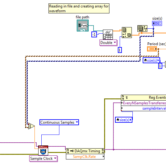
enjoy a rate of clock error (think this is 0.000): define a dummy value?
Hello
I use a VI and a USB-6211 to read in a txt file and this file as an analog waveform of voltage output and at the same time send a meter synchronized with this analog waveform. At the start of the VI, I have several errors:First of all :-200077occured to the property Node DAQmx Timing(arg 5) in DAQmx Timing (sample clock)
Property
 ampClk.rate, you asked: 0.00000, valid values begin by... etc.
Then:-88709, or the possible reasons: the specified operation cannot be performed because a task was abandoned or a device has been removed from the system... Task Name_unnamed task<22>
If I restart the VI (without closing), it works.
I think that what is happening, is that the property node is the research of sampling before clock frequency was calculated. The way I currently put it in place, the VI reads in the file and divides the number of samples in the file with the desired waveform period. (the typical file has ~ 100 samples), periods are about 1 sec.
I'm trying to find a way to have the sample clock to wait as the file to read before he seeks the sample clock frequency, or a set that a dummy valuethat not null will be replaced as calculated from the size of the file and the period. A search for 'sequence iof events', 'wait', etc. turned up other subjects.
I have attached the VI and a txt file/waveform sample.
Thank you
Gabriel
Hi Gabriel,
The simplest and easiest way is to use data streams: use wire instead of local variables and LabVIEW will be figure in the order of operations based on how they are related:
The less straightforward way is to use a sequence structure, which I wouldn't recommend here because it's just more complicated things:
Brad
-
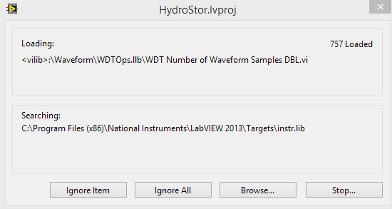
Dependencies in vi.lib and loading of the wrong place user.lib
Hello
I'm having a weird problem trying to load a LabVIEW project in 2013. Whenever I open the project folder, it keeps looking for files in vi.lib and user.lib in the wrong place. Instead of search in files (x 86) C:\Project \National Instruments\LabVIEW 2013\vi.lib, he look in C:\Program Files (x 86) \National Instruments\Targets\vi.lib
I have manually browse for each file in the directories vi.lib and user.lib and point each a return to real folders. But in the project folder itself, all the files I have loaded just said that it is still in conflict. When I try to resolve conflicts of files, they disappear for a second then come back.
I can't make LabVIEW for functions in the directories user.lib and vi.lib normal, it keeps adding targets in the destination.
I tried to do a recompilation of mass, and which does not at all help.
When I load the project, select a few dozen files vi.lib and user.lib, do a save all, close the project, and then re - open, I need to reconnect every file again. It still seems for all... \Targets\vi.lib instead of just \vi.lib.
This isn't the case for all projects, just this one it seems.
The files are in the right place based on the path under "loading". If she says it's in
: \Waveform\WDTOps.llb\WDT number of waveform samples DBL.vi, it really is. The path on the top is right, I don't know why LabVIEW is not find anything. Any idea how I can get this project to stop looking for vi.lib in the folder target?
ng1902 wrote:
I managed to get the errors to stop copying vi.lib and user.lib files in the subfolder of targets.
This could be dangerous and cause problems. If it's possible after your project.
When I saw this sort of thing in the past, it was usually because of a broken dependency I got didn't really need. I would say through your dependencies (in project) and search for the odd elements glyphs showing errors. Try to find out why those are dependencies and remove unused code, or links to the missing code. Resolve all conflicts and then make a backup of all.
In the past, it happened when I tried to copy a project as a new project, and then changes the code snatch which was unnecessary, but there was always a code in a disabled structure that could not be loaded causing a kind of problem of linkage project.
-
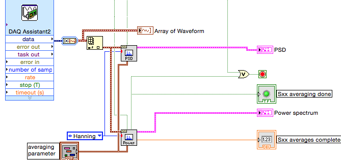
Amplitude of power spectral density is about 1e6 times higher than it should be
Hello
I use vi of power spectral density (PSD) and power spectrum vi in the process the same time acquired by data acquisition (attached figure) signal. I sent in a 0.1V sinusoidal signal of 1 kHz in data acquisition, and the power spectrum gives me the right power RMS at 1 kHz (which is 0.05), but DSP vi gives me 1670, which isn't fair. The amplitude THAT PSD gives me must be smaller that the power of amplitude spectrum gives me. This is supposed to be a simple treatment, but it drives me crazy. Is someone can you please help me solve this problem?
Thank you very much.
INSA
If you convert the dynamic data Type (badly) from the DAQ Assistant for an array of waveforms, sampling rate information must be included and none of your additional calculations is required because power Sprctrum and the PSD VIs will take care of this... This is what Dennis mentioned in his post.
We cannot do a lot without data. Please display waveform data type and add a waveform table indicator. Run the VI until the indicator data. Stop the VI. On the Edit menu, select use current default values. Save that VI, possible with a different name and post it. We will then have access to your data.
Lynn
-
First a clarification on the issue of 100ms. It's ONLY a problem with "Wait until the fact" behavior of meter output. Due to the hardware architecture, question us the material every 100ms to see if the pulse is complete. This does not change any of your output.
With this in mind, you should NOT see any problems with the AO. AO has a dedicated timing and engine when you do a finished we ouput only data that you ask us to. Lets take a look what your VI. You want to ouput 10000 (sampling frequency) *.001 * 2 (given that you add two waveforms) samples. This is equivalent to 20 samples, or 2 ms of data. However, you are not writing the number of samples for your VI calendar configuration. The default value is 1000, or 980 more samples, or 98 ms.
Just write the number of samples to your calendar VI and all should be good.
-
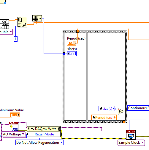
Analog output using DAQmx task
I need a signal to analog waveform using 6259 output, I followed the instructions to "Build an analogue output VI in NOR-DAQmx" in the developer area OR, when I run the code I receive thefollowing error message
"Error-50103 occurred in the DAQmx write (analog 1-d Wfm NChan NSamp) .vi:3.
Possible reasons:
The specified resource is reserved. The operation could not be performed as indicated.
Task name: _unnamedTask<1A> '
and when I press "continue" it goes ahead and track waveform on the front panel, but do not display it on the test panel in max could someone suggest how I might solve the problem?
Hello
Could you try the attached VI and let me know if it works?
I noticed that you receive information of the waveform sample clock, but the type of dynamic data that you use has no data of time in it!
-
Why my sample rate does not match the output of timestamps in the waveform?
Hello
I run a simple application to read the data of two pressure sensors output signals 0 - 5V to a NI9215 module, and one connected to the 9237 module load cell. They are housed in the 9172 chassis.
I am new to DAQ and labview, and I find it difficult to reconcile the sampling frequency that I put in the sample clock and the apparent rate data (according to the timestamps in the waveform that I output to a text file). For example, if I ask 100 Hz rate (and 10 samples to read), the data appear to sample at 1612,9 Hz. If I ask the sampling frequency of 1000 Hz, outgoing data is 1612,9 Hz to 20 kHz, the data came out to 25 kHz.
Can someone tell me to trust the timestamps given in the waveform that is written in the text file, and if there is a way to check this? If this timestamp is correct, how can I force the application of sample data at the requested speed?
As a secondary issue, in my attached VI, you can see that I have an attached to an array of construction shift register. I can't understand how to initialize the array outside of the loop as it clears the table before the next time I run the program. Any advice?
My VI is attached.
Thank you
Claire.
Hi Marc, thanks for the quick response and the right explanation. It's all much more clear now.
Have a great weekend,
Claire.
-
collection of samples of first N and the last of waveform
Hello
I am trying to acquire the circuit voltages. I had a waveform that I have attached to this message. I want just the signals of temps.002 a.007 in this graph. To select a particular sample, what will I do? I don't have enough knowledge in labvie... So please help me.
Thanking you,
Manu
You can republish ot the LabVIEW forum; This is the SignalExpress forum.
We do not have enough information to answer your question fully. To get the de.002 a.007 on the chart data, you need a subset of your data table. Determine what is this subset and fetch it depends on how you got the data and in what form it is in. The two most likely forms are a type of dynamic data (dark blue wire) and the type of waveform data (Brown wire). "For the type of dynamic data, use the Express VI of Passage is extracted from the Express ' Signal handling palette. For the type of waveform data, use the subset of waveform is VI in the palette of waveform .
If that does not answer your question, please post code you so we can give a better answer.
-
How to create a waveform from an array with arbitrary sampling rates
Hi I know that sounds a little silly,
Suppose I created a simple table of figures DBL with a structure For, Say size 16. now, I want to create a waveform DBL with these 16 numbers at an arbitrary sample rate. so if I use 1 kech. / s to the sampling frequency, I want to have a waveform with a duration of 16 milliseconds.
Please help me, I need it too
TNX
Hello
You must use the wave to build function as shown here: http://zone.ni.com/reference/en-XX/help/371361G-01/lvwave/build_waveform/ . Wire you your Board at the entrance Y and then wire the dt of entry in your sampling rate.
-Zach
-
missing samples in the waveform graph
Hello world
When processing a file .wav into pieces, I noticed that there are missing samples on the waveform graph where two pieces must be met for the display. What could be the cause of this? Any help appreciated. Thank you!
Milan
Your method of reading in pieces in a for loop is create a table 1 d of waveforms with the tunnels of automatic indexation. It is as well as what you have the data appear in different plots. I don't know if that's what you want.
But if this is the case, the problem is that you get to the last point of the first plot, and the first point of the next parcel is a different value. Because they are two different plots that you do not get the line to join them, as you do between points that are part of the same plot.
Maybe you are looking for
-
Having 2 /iTunes Apple id accounts, is a problem. To merge or delete one of them would simplify the use of my devices.
-
I want to classify several bookmarks in a folder. What are the steps to make a new folder?
-
How can I turn off the prompt to start in safe mode?
I noticed that, since the 18th of Firefox on Windows 8, I observed here safe mode window: https://support.mozilla.org/en-US/kb/troubleshoot-firefox-issues-using-safe-mode?esab=a & as = aaq #w_safe-mode-window_2 pop up when Firefox crashes asking me t
-
NB100 - "Update Manager" will automatically load and start to run
Whenever I turn on my NB100 (Ubuntu ReMix) the "Update Manager" application load automatically and begins to run. How can I stop this happening? Thank youDavid Lowe
-
My iMac will be either reboot or shutdown of the apple desktop icon
My iMac will be either reboot or shutdown of the apple on the desktop icon. Items saved on the desktop disappear and the menu from the top of the screen disappears, then it is just in this mode for ever more. I then use the switch to stop, which is c