9401 counters
I use the 9172 and I have a question for the 9401 module. I have an encoder (which requires a counter) and a Devantech SRF05 sonar (which requires an entrance and an exit of meter). Can I use 2 counters on the 9401 and a digital output signal?
Hello cend.
The cDAQ-9172 chassis has only two counters total. The counters are on the chassis, not the 9401 modules. Therefore, you can have two tasks only one meter or a two meter task that runs at the same time.
So, if your sonar uses a counter of entry and exit, you will not be able to use counters anywhere elsewhere in the chassis.
The cDAQ-9174and 9178 9188 have all four on-board meters would be probably more suited to your application. These counters are accessible from any location.
Kind regards
Tags: NI Hardware
Similar Questions
-
How can I use two counters simultaneously to pulse width measurment
Hello, everyone!
I'm new to Labview. I currently have some cDAQ9171 and width measurment with 9401 impulses. My understanding is that the 9401 was 4 meters, which means that I can use these meter separately. However I have the following problem.
1. I use ctr 0 and ctr 1 (PFI 1 and PFI5) to measure two different impulses. However, it seems that there is an interference between two counters. How can I make two counters working simultaneously and separately?
2. I first try a pulse width measurment counter in Labview signalExpress. My pulse width is about 0.4ms. However, I can't get the right result, if I choose the starting edge is on the rise (the results always around 20ns. Only if I revise my pulse and pick the starting edge is down, I can get reliable results.
I'm confused about these issues for about 3 weeks... Is there someone can help what can I do with that?
I have attached a simple vi...
Thank you very much!
-
Best way to generate signals of activation (square wave) with my 9401 on my 9022?
Hi, I tried seriously over the past two days to find the best way to do it. I am trying to generate a very precise square wave, controlling the duty cycle and frequency, with the OID on the 9401 in testbed cRIO 9022.
I have a VI that is theoretically able to do this, but whenever I try to go above 5 Hz or more, duty cycle and frequency becomes inaccurate (I have watch on an oscilloscope), various a lot too for my needs. I have a feeling that this is caused by my addiction on the calendar software controlled, with errors at the time (of the ms order) accumulate as they get processed and the signal is sent. I have attached a piece of code that illustrates the basic idea of what my VI have in them.
I have avoided the square wave generators integrated because I could never work to satisfaction, but I can work with them so that will solve my problems. Selection structures and cases prevent the user to exaggerate their inputs. Unwaited so the loop was just to test.
I'm running the 9022 as target in real time, but also tried to run in the FPGA and I was able to produce much more accurate signals using FPGA VI square wave, displaying a Boolean variable, but I couldn't see the best way to get double precision variables to work with everything (and I want more precision than variables FXP enabled clock 40 MHz).
I feel there is just a mistake in my approach here. I've seen other discussions where people throw around using meters to edge of the test bench to produce a square wave, and I see the example screws as Gen dig pulse - continuous Train, I'm not sure if initially these screws DAQmx for my situation (eg. How to identify my counters, because they are clearly not Dev1/ctr0 by default in these examples)
Thank you
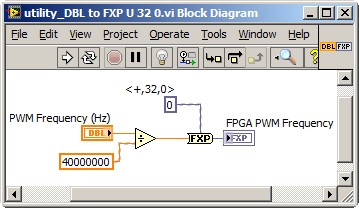
Dealing with the representation of Point fixed and all is a reality for LabVIEW FPGA<= 2011="" programmers.="" you="" might="" build="" a="" small="" sub="" vi,="" such="" as="" the="" one="" attached,="" to="" encapsulate="" the="" frequency="" calculation,="" thereby="" abstracting="" the="" conversion="" formula="" and="" fixed="" point="" data="" type.="" you="" can="" adjust="" the="" properties="" of="" the="" floating="" point="" input="" control="" to="" accept="" only="" valid="">
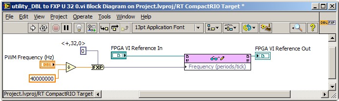
This implies the series VI void on the host of the RT, and not on the FPGA target. So, you also need nodes in the Palette of the FPGA Interface to send PWM fixed Point RT frequency to the FPGA. The complete solution of frequency may resemble the following. It is common for FPGA programmers to build a collection of thesesub screw, that make up the API for hardware.
Note that 40 MHz is hard-coded. For increased flexibility, consider making the FPGA clock rate an entry to the Subvi with a default value of 40 MHz.
-Steve
-
9401 buffered output digital clock sample source
Hi, I would like to generate a pulse train with a defined number of pulses, according to a defined periodicity. I use a NI9401 module in the Groove 3 CompactDAQ chassis so that I can write the required buffer sample 2047 pulse train. The problem I have is I am unable to choose any clock source slower than the time base of 100 kHz, which means that the buffer can underflow very easily. I would use a 4 kHz clock source, but cannot find how do. If I want to generate a source of the clock of one of the counters, I must have the 9401 in slots 6 or 7 which then do not allow for generation of digital signals in the buffer...
Hi, JPP,.
Access to internal counters, even if modules are connected in the Groove 1-4 of the cDAQ chassis. Note this site 6 & 7 are necessary only if you need external access to counters as task of counter in the buffer, the measures of frequency/period, etc... Since in your application, all you need is to generate a continuous pulse train and access its output internally to clock output your digital correlated, this shouldn't be a problem with your DIO module into the Groove 4. Please take a look at the following link for more information.
With the help of internal counters on one NOR cDAQ-9172 as a sample for other tasks clock
http://digital.NI.com/public.nsf/allkb/EEB574335BA0B4EB862572060055E9DD?OpenDocument
I would also like to refer to an example on our site which shows you how to use your correlated digital i/o clock counter. I hope this helps.
NOR-DAQmx: Digital Correlation of e/s with NI CompactDAQ and LabVIEW
-
Sampling frequency for digital sampling (cDAQ-9172 & NI 9401)
Hello!
I have a cDAQ-9172 with NI 9401 C-series (digital) module. I would like to taste the digital inputs with a sampling frequency of e.g. 400 or 200 kHz. My problem is that I can only choose a clock 100kHzTimebase and therefore only get a sampling rate of 100 kHz. The 20MHzTimebase clock is too fast, as it gives me a sampling rate of 20 MHz). Is it possible to get a defined user e.g. 200 kHz sampling frequency, dividing for example down the clock of 20MHzTimebase?
Thank you! Last post and this article using the internal one or cDAQ chassis counters has solved my problem.
-
A measure of speed high speed with encoder in quadrature and NI 9401 on cDaq
Greetings,
We use an encoder in quadrature with 360 pulses/turn on the tracks (track A and B) and no trace of Z to measure motor speed at startup. Data acquisition, we use a NI 9401 in 9178 cDaq chassis and a pc with LabVIEW. The problem is that the start-up period is relatively short (less than 1 second), during which we measure speed as precisely as possible. The speed range is from 0 to 10000 RPM.
What type of measurement method that you would recommend.
Here are a few methods that we have already tried:
-Measure with DAQmx CIFreq--> high frequency with 2 counters: speed measurement, but with a very big mistake (+ 166 RPM).
-CIFreq DAQmx--> wide range with 2 counters: good speed data but more slow measurement,
-CICntEdges DAQmx (counting separated the two lanes, speed conversion): very incoherent speed data.
Thanks in advance for your help.
Matej
I would definitely say a 4, the measure of a low freq called option with 1 meter. (Frankly, I've never been
fond of this name because it is useful for freqs much higher than what I expect most people think "low freq".) This
is the method that I almost * always * use for frequency of counter measures. It works really well to capture transitional
variations in speed.
10000 rpm and 360 cycles/rev, you are looking at a maximum frequency of 60 kHz. The frequency measurement mode 1 meter
There will be 80 MHz internal clock by encoder cycle edges, then you will get more than 1000 strokes per measure. The point
that means only 1 number of quantization errors, you can expect<>
Further, you can average overall, say, 10 samples to you give even better accuracy and you could still be a data capture
rate significantly higher than the probable bandwidth of your mechanical system. (The average would just clean the jitter and noise and would not
Hide answer true mechanical characteristics).
-Kevin P
-
cDAQ-9174 cannot use the counters of 3 or 4
Hello
I try to display the entry of a potentiometer and 3 encoders of Quad. I have a CDAQ-9174 with a 9215 OR (for the POT) in the slot 1, 9411 or in slot 2 and a NI 9401 in the Groove 3 (soon to another NOR 9411 when it happens).
If I run the example 'Measure angular Position.vi' on each individual encoder (by selecting either modules on counter 0), I can see all three encoders work properly (exit count increments and decrements as expected)
If I run the Test panels able and automation, I see all three encoders switch their respective 2 channels each.
But when I change 'measurement Position.vi"to have all three separate entries (I copied the task of creating and all its entries twice, then expanded the while loop to have three different DaqMX Read vi, then 2 clearer spots on the right side (output) at all in a loop), I see only 2 encoders increment and decrement.
I do not use Index Z entries, I changed the type of decoding to X 2 for all three. I tried to change that, but I especially get the same result (2 encoders working, is not 1).
I changed the encoders are the use of counters to 0, 1, and 2. Only the assigned to counter 2 encoder does not work.
I tried to use meter 3 - same problem.
Is there a way to confirm that the cDAQ-9174 counters all work? I tried all three in the test panels and they seem to be good?
A cDAQ-9174 can manage 2 Quad encoders using 2 signals of each (A and B signals - A for metering, B for management)?
I have something configured incorrectly? If you use two Modules of entry at the same time, is it some additional configuration that must be done?
Really appreciate some help here.
Thank you
Sam
Yes, we use the 9.0.2 version drivers and no there is no error message.
Turns out we had wired it incorrectly for Counter 2 use. Being on the second module, I thought we had wire the same way the first module has been wired - not realizing that counters need a provision of the specific pins.
Thank you for looking into this.
-
Satellite A100 PSAA2 - HDD counters every 30 seconds after the BIOS update
Hello
I recently renewed my BIOS to 2.20 to 2.30 on a Toshiba A100 PSAA2, after that my disc HARD spindows every 30 seconds when not in service, the shortenes course, that's life. I tried, clean XP SP3 and other Toshiba utils, programs like drive HARD silencer, Ubuntu, now I'm working on Win 7 RC, the problem remains, even when I select No to turn off the hard disk in the Windows settings.
I think that Toshiba set the counters of setting in the BIOS to shorten the life of HARD drive... How downgrade the BIOS to 2.20 v., this watch WinPhlash I have an older BIOS and could not crush him.
Can someone help me?
Have you tried to reset the BIOS to its default settings?
Only an ASP (Authorized Service Partner) may downgrade a BIOS. There is a list of the ASP on the Toshiba site.
-
I can measure the speed of the NI 9401 fan & cRIO 9075 under Scan Interface?
Hello
I am currently using OR 9401 & cRIO 9075 to develop a project, which is to control the CPU fans.
Since I have to communicate with other instruments by serial port, while I have a NI 9870 module to implement the instrument control.
I finished the part of control instrument under scan mode and would like to add the function of the fan speed reading.
Now, I wonder if there is a problem when I choose the Scan Interface to deverlop the program.
I found the following tutorial, he uses the FPGA interface to impement the acquisition of control and PWM frequency.
http://www.NI.com/white-paper/3230/en/
So if the function of the fan control only developed under an FPGA interface, I have to rewrite the control instrument part, seems to be a bit complicated...
You can use the hybrid mode.
http://digital.NI.com/public.nsf/allkb/0DB7FEF37C26AF85862575C400531690
-
Is a module able to drive a small 9401 (5amp) SSR with a 4-15 volt of entry?
You should consider using a buffer chip that can produce current, you need, like this. This will require a 5V supply, but it does the job.
-
How to access the counters in cDAQ9174 / NI9403 with C / Matlab
Hello
I read that the cDAQ9174 has four available counters. However, they need to be interfaced via another card and they are now directly available to the user. How do I with e/s digital NI9403 card? How could I do with LabVIEW but with C/Matlab?
Thank you
Jan
Hello, Ulysses,.
normally all modules with the DIO 8 inputs or less.
-
Hello
We ordered the cRIO 9035 system with several Modules.
One of them is the NI9401.
I want to use this module to count the pulses of a flow meter.
In front, I am a beginner and started just look at a lot of tutorials and created Basic VI
- This Module has onboard counters, or is it only possible to use the 'material' - counters in the chassis through this Module?
I ask this, because I can put the Module via "Digital specialty Setup" as a counter.
If I do, it would be possible to simply create a while loop, place the channel on the inside and tie him to a digital item?
Or is the only way to count impulses (rising edge) to use VI as the 'edge counter VI' the example of VI? - My flow meter uses a Hallsensor and produces rectangular pulses at 40 Hz max.
It is absolutely necessary to use a FPGA or can I use a VI on the host computer?
We use 4 of these flowmeters (and many more sensors like Termocouples (NI 9211), solenoid valves (NI 9482) or a AKD-servomotor (NI 9472).)
All the measured data should be written to a file (for example, form exel).
Magnetic valves must be triggered if a certain number of pulses is counted.
Yet once, it is absolutely necessary to use a FPGA or can I use a VI on the host computer?
I know there is a lot to do and I have to learn a lot more, but I'm on it (its for my Masterthesis).
For now, the answers to questions about existing or not existing edge counter would be great.
Thank you for your support.
Greetings from the Germany,
Lukas
Lukus salvation,
Greetings from Munich (since it is a public forum, I am obliged to answer in English, in any case).
(1) when you use a cRIO you don't have a strict meter limitation (especially if you program the FPGA) for your digital inputs. Maybe read you something about that and that only applies to the cDAQs (because he (mostly) counters come from cDAQ chassis so they are more limited)
"If I do, it would be possible to simply create a while loop, place the channel on the inside and tie him to a digital item?"
FIX
"Or is the only way to count impulses (rising edge) to use VI as the 'edge counter VI' the example of VI?
I'm not sure which exact VI you are referring to, but on the FPGA you could implement a custom counter. That would work too.
(2) you can do two ways (Scan Engine Mode and FPGA)
If you write a master's thesis, you may be eligible for a greatly reduced price. The course Embedded Control and Monitoring (http://www.ni.com/training/embedded/) would be very useful for you:
Forderprogramme as research, training und Lehre - National Instruments Germany GmbH
http://Germany.NI.com/academic/training/programs/diplomandBest regards
Christoph
- This Module has onboard counters, or is it only possible to use the 'material' - counters in the chassis through this Module?
-
I have a 9401 on a chassis 9188 module. What I want to do, is to have 3 DI, 1 and 1 PWM.
I thought I could put the DI 3 on channels 0,1,2. Output channel on 6 and a PWM using a digital channel 7 (-1). In this way, that they would be grouped with 1 4 input channels and the last 4 production by the manual.
The problem is I get a 201133 error that says that the device can be configured for input or output due to another task or directions when I try to run everything in the same vi. I can make the DI and DO tasks with no problem OR the PWM task without problem. I tried to book the tasks with the DAQmx control task VI as the suggested error, but not luck.
Is it possible to do all this on the 9401 at the same time?
Bryan
You won't be able to use 1 DI, 1, and up to 4 meter which are material tasks timed at the same time when you use a 9188: http://digital.ni.com/public.nsf/allkb/5E0B829E50ADE1BC86257AC50062B2D2?OpenDocument
In addition, you will need to make sure that you book the tasks to avoid the error of 201133 with the 9401: http://digital.ni.com/public.nsf/allkb/0495B7D5E2345DF386257730007EFD17
-Mike
-
How cascading 2 counters for 64-bit timer?
I work with the PCI-6225 card which has several counters. I configured CTR0 to 20 MHz. I get the CTR0 time by calling the OR-DAQmx C function 'DAQmxReadCounterScalarU32' to get the number of frequencies and then by dividing the number of frequency of 20 MHz for a time value. The maximum time value that may be getting is that of 214.7483648 seconds (2 ^ 32 / 20e6). I want to stunt/link two counters (CTR0 and CTR1) to get the frequency of 64-bit values. To be clear, CTR0 configured as CTR1 configured as 32 byte MSB and LSB 32 bits so that whenever CTR0 reached maximum values and "roll" then CTR1 would be incremented by 1. How can I do this using the C-NOR-DAQmx features?
Thank you
Ian
Hw do will be more reliable, but here are two possible ways to approach it in sw.
1. There is a DAQmx property with a name similar to "Terminal number reached" that I have used in LabVIEW but do not know the underlying C syntax. When you query this software, it will return a true once, is reset to false. I'm sure that he will return a true even once on the * following * the event rollover, but you would be better double-check me on that. Not knowing your entire application, I guess you will probably need to be prepared to manage several inversions.
2. in certain applications, rather than establishing a measure which follows the cumulative time, you can configure the hw to measure periods and then take a NAP in sw to get your 'timestamp '. Unless an individual interval could exceed 200 + seconds, you can just do your accumulation of software with a 64-bit data type.
Technically, you can even do both. Do a measure 32-bit intervals hw, do a query of software for the event of tc, accumulate intervals & counties of reversal in a 64-bit int.
-Kevin P
-
cDAQ-9178 & NI 9401 - ASM: incremental Rotary encoder works is not beyond a certain frequency
I use a chassis with a NI 9401 DIO module 9178 cDAQ. I'm trying to convert the output of a rotary incremental encoder ASM (in radians) to rpm.
Sensing head (PMIS4-20-50-240kHz-TTL24V-Z0-2M-S)
Snap ring (PMIR7N-20-50-M-20)
The encoder outputs 2500 pulses per rev (output 5V TTL). The maximum speed which will see the encoder is 2800 rpm, which is equivalent to 2800 RPM * 2500ppr/60 = 116,667.67 Hz in terms of frequency.
Since the NI 9401 of the operations specifications:
Maximum of the input signal switching frequency by the number of input channels, by channel
8 input channels... 9 MHz
4 input channels... 16 MHz
2 input channels... 30 MHzI use only 1 channel, so I'm assuming that the 9401 should be more than capable of handling the 116kHz which the ASM encoder is spit.
Everything works fine until about 2100 RPM (~ 87, 500 Hz) but then I begin to see a drop in rpm, followed by a flattened behavior, then a slight increase. But never more than 2100 RPM. Our test unit is inspected for other reasons at the moment so I can't produce a plot of the behavior (I can reupload later). I think this must be a matter of aliasing with the meter or something of the sort. I have a digital filter set in place with a minimum of 4.0E pulse width - 6. It is two times smaller than the width of minimum pulse at a frequency of 116kHz (0.0000085714). I don't think this should have an impact on the calculation.
Any suggestions? This value of RPM is essential to our application.
Thanks in advance,
-MB
brown_ktr wrote:
I have a digital filter set in place with a minimum of 4.0E pulse width - 6. It is two times smaller than the width of minimum pulse at a frequency of 116kHz (0.0000085714). I don't think this should have an impact on the calculation.
A 116 kHz frequency, the period is ~8.57 us, but the pulse width half duty cycle of 50%. Ascent/descent time factor, and it is quite possible that 4 US is too long for your encoder signal.
The shape of this graph supports this theory, if we consider that there is variation in the exact pulse of each encoder pulse width. The shortest pulse is ignored when the filter starts to kick in, and the speed of ROTATION increases pulses longer and longer are ignored then as well.
Try to decrease the minimum pulse of digital filter (US 2 or even 1 US) width and see how it goes.
Best regards
Maybe you are looking for
-
Synchronization and backup from iPad to the computer using iTunes
Since the last update, last week, did someone else with problems of synchronization/backup of their Air iPad with their computer via iTunes? iPad OS 10.0.2, iMac OS X Lion 10.7.5 Air (updates is no longer available for this computer). I had no probl
-
HP pavilion 15-n248sa: a media computer driver needs is missing on 8.1
"Sorry I have European account. Hello I have a problem, I used before archlinux now I want to reinstall agaion windows 8 in my 'Hp Pavilion 15-n248sa' hp, and I have problem during the installation I get an error " A media computer driver needs is mi
-
Any chance we can get confidence * WIFI networks?
I like the feature to be on a Bluetooth device (in the car) and stas unlocked phone But what about when we are at home or at work, on a specific WIFI network? We might have this feature of this situation? I know that the bike will do things like read
-
stream HP 11: 11, 5G wireless stream
My new HP flow 11 recognizes my slower wireless but not 5g - it isn't see it. The review on the S11 I read before purchase. said it would... it was incorrect?
-
Cannot activate Windows 7 install
Hello My MS Windows 7 product key stickers worn and there are about 5 characters that I can do is more outside. Would it not possible to recover these characters or appear a new key? Best, Need help