9401 on cDAQ9178 acquisition of 2 coders
Hello
I have a problem to pour two acquisitions buffered on a NI9401 card mounted in a cDAQ9178.
If I try to do a task (in MAX) with ctr0 and ctr1 Escalin 9401, I got a message telling me that I can't have just a meter by task.
If I spot two do, execution of LabVIEW I get the message:
The 201133 error occurred in: DAQmx start Task.vi:10
Possible reasons:
The device cannot be configured as input or output car lines or terminals connected to it are used normal another task or another connection. This operation requires that all lines and all terminals are temporarily reserved for communication, which interferes with the other task or connection.
If possible, use DAQmx - control task pour book tasks that use this device before scheduling these tasks. Otherwise, free UO déprogrammez the other task or disconnect the other connection before you try to configure the input or output device.
Device: E_COMPTAGE
Digital port: 0
Lines: 4, 6
Task name: _unnamedTask<2C>
En conclusion: can we make an acquisition, continuous and simultaneous two coders on the itself 9401.
Thanks for your help.
Hello.
This is a way of programmer that should solve your problem.
Kind regards.
Tags: NI Software
Similar Questions
-
I can measure the speed of the NI 9401 fan & cRIO 9075 under Scan Interface?
Hello
I am currently using OR 9401 & cRIO 9075 to develop a project, which is to control the CPU fans.
Since I have to communicate with other instruments by serial port, while I have a NI 9870 module to implement the instrument control.
I finished the part of control instrument under scan mode and would like to add the function of the fan speed reading.
Now, I wonder if there is a problem when I choose the Scan Interface to deverlop the program.
I found the following tutorial, he uses the FPGA interface to impement the acquisition of control and PWM frequency.
http://www.NI.com/white-paper/3230/en/
So if the function of the fan control only developed under an FPGA interface, I have to rewrite the control instrument part, seems to be a bit complicated...
You can use the hybrid mode.
http://digital.NI.com/public.nsf/allkb/0DB7FEF37C26AF85862575C400531690
-
NI 9401 pulse width measurement.
Hello
I'm not sure that I understand very well the pinout diagram. At the present time, I have a NI9401 in a NI 9172 chassis.
DIO0 and DIO1 are connected at the gates of light. I have an opto switch and I want to measure the pulse width when an object blocks passes through the slot. Can I use one of the other free entry of the for do?
The entries are DIO2, DIO4 and DIO5.
The other IO pins are used as triggers.
See you soon
K
Hi Kamilan,
If you explore in the measurement and Automation (MAX) and find your 9401, you can right click on the device and select "Pin of the device" which pulls up a window that says what features each pin on the device. For example, according to this document, DIO2 is PFI2 to THE CTR0 CTR0 B and FREQ OUT.
To answer your second question, do a right click on your device and create a new task for your 9401. "You should do an acquisition of signals" counter input "pulse width and select CTR 1 on your device. Once you do this, you can configure the parameters of your task and Max it will tell you where you need connect your signal source, which, for me, is DIO5.
I would like to know how it works for you, thank you!
-
With the help of a NO-9401 read the angular Position and trigger a reading I
Hi all
I am writing some software dependent vs angle chart and to the monitor when the buttons are pressed. The software allows all DAQ lines to be configured so that multiple configurations data acquisition can be used.
Currently, I peut use my NOR-9411 read the angular position of my quadurature encoder and trigger the playback of my entry (measured with a NEITHER-9219 or 9237) load on a rising edge of A or B input terminal analog. Also, I can configure the software to do the same thing with a card OR-6259.
My problem is that when I switch to a NO-9401 to read my meter task, I can no longer use the input terminals A or B to trigger my analog input. I get error-200414 saying that the entry A (PFI0) is an invalid clock source.
I know that the 9401 is configurable by nibble for input/output lines0:3 and 4:7, but how that affects the ability of a trigger, a route line PFI?
Measurement and Automation Explorer shows it as an acceptable way of PFI0 AI/StartTrigger and AI/SampleClock.
I joined the my code section that defines the tasks and that causes the error. You take a look in the Utilities folder and open the Tasks.vi create.
I am writing in LabVIEW 2011.
Thanks for any advice,
Rob Afton
Test lab engineering intern
Found my answer here if anyone has the problem:
-
A measure of speed high speed with encoder in quadrature and NI 9401 on cDaq
Greetings,
We use an encoder in quadrature with 360 pulses/turn on the tracks (track A and B) and no trace of Z to measure motor speed at startup. Data acquisition, we use a NI 9401 in 9178 cDaq chassis and a pc with LabVIEW. The problem is that the start-up period is relatively short (less than 1 second), during which we measure speed as precisely as possible. The speed range is from 0 to 10000 RPM.
What type of measurement method that you would recommend.
Here are a few methods that we have already tried:
-Measure with DAQmx CIFreq--> high frequency with 2 counters: speed measurement, but with a very big mistake (+ 166 RPM).
-CIFreq DAQmx--> wide range with 2 counters: good speed data but more slow measurement,
-CICntEdges DAQmx (counting separated the two lanes, speed conversion): very incoherent speed data.
Thanks in advance for your help.
Matej
I would definitely say a 4, the measure of a low freq called option with 1 meter. (Frankly, I've never been
fond of this name because it is useful for freqs much higher than what I expect most people think "low freq".) This
is the method that I almost * always * use for frequency of counter measures. It works really well to capture transitional
variations in speed.
10000 rpm and 360 cycles/rev, you are looking at a maximum frequency of 60 kHz. The frequency measurement mode 1 meter
There will be 80 MHz internal clock by encoder cycle edges, then you will get more than 1000 strokes per measure. The point
that means only 1 number of quantization errors, you can expect<>
Further, you can average overall, say, 10 samples to you give even better accuracy and you could still be a data capture
rate significantly higher than the probable bandwidth of your mechanical system. (The average would just clean the jitter and noise and would not
Hide answer true mechanical characteristics).
-Kevin P
-
Digital output with NOR-9401 in cDAQ-9174
Hello
I have a cDAQ-9174 with an e/s digital NOR-9401 module. Now I want to output Digital signals on line0:3
$line0: Boolean 1 time = 10ms
Line1: Boolean variable 1 time = 20ms
row2: Boolean variable 1 time = 30ms
line 3:20 pulses (period = 250us, duty ratio = 0.5) after a time = 40ms
the value of line0:3 must be Boolean 0 after 45ms
Can someone let me know what I need to work to solve this please?
Thank you all for your help.
Concerning
Bing
Thank you Christian for your quick replay.
I have some experience in programming of microcontroller with C. I learned LABVIEW for about 1 month and followed a lot of demons in line and tutorials. I know that nodes DAQmx Data Acquisition screws and fundamental property.
As I said at the beginning on the $line0, lin1and line2, they serve to control the relay in my circuit. 10ms could be controlled with the OS clock. Pulse of line3 series is used for IGBT gate signals, which is the critical moment. I want to use the clock machine to accurately control line 3 and synchronize at the same time the pulse with analog inputs from an another two NI9206 modules in the same cDAQ chassis.
I just want to know more on the digital line demand signal relay output and a correlation between the line of analog input-synchronized finished pulse output. Waveform diagram is locked.
Thank you.
Bing
-
Two ports in the NI 9401 module?
Hi all
I'm relatively new toLabView, but I have to say that I'm enjoying learnicg it. My problem is that I need to generate two independent signals with a connected NI 9401 module a OR cDAQ-9172.
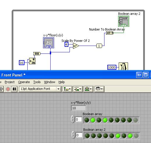
I need to generate a sequence of bits to control a demultiplexer, the sequence is 0000, 0001, 0010, 0011... 1111, 0000, 0001... So far, with the help of this great forum, I managed to generate the sequence, my problem is that I need to use the other bits to control the spindle enable (bit) of an another demutiplexers cascading.
I read that the NOR-9401 is configurable nibble, so I understand that I could use bits 0:3 to generate the sequence and 4:7 bits to control bits allow for demultiplexers. But until now I could haven´t this task, I see all the 8 rows as a single port and I was not able to learn how to configure two ports as outputs time and generate different signals.
I'm using LabView 8.6
Could someone help me please in this task, I would appreciate any help really.
Kind regards
Joseph
Hi Joseph,.
I thought after studying the best way to do it, not with the crazy arry.
Use the power level 2 - n = 4 and x being the u8. You can then wire the output for the upper nibble DAQ.
Note: If you have placed a number of u8 to a data acquisition task configured for the 0 line - it will seek only to bit 0. It is the extension of what ever and the number of selected lines.
Hope this helps

-
I get upgraded my laptop (HP for laptop - 15-r224tx) for Windows 10 but I can't find the driver for the controller of PCI Data Acquisition and Signal Processing. Please help me find the right one.
Thank you!
You are the very welcome.
It is the latest version of the W10 driver for this card model... see if this solves the problem, if you have not already installed this driver.
This package contains the installation package driver for the controller wireless LAN Realtek RTL8723BE/RTL8188EE in the laptop models running a supported operating system.
File name: sp72517.exe
-
PCI Data Acquisition and Signal Processing controller driver
I installed win 8.1x64 on my HP Probook 450 G2, but miss me the driver of PCI Data Acquisition and Signal Processing controller.
Can you please help?
Thank you
Leontina
Hello:
Please see if installing the Intel Chipset driver installs this device.
https://Downloadcenter.Intel.com/Detail_Desc.aspx?DwnldID=20775 & lang = eng & ProdId = 816
-
I just installed Win7 Pro x 86 on my Z600 workstation. It was an upgrade to Windows XP Pro. I'm missing the driver for PCI Data Acquisition and processing of the Signal and Hardlock USB 1.02 controller in Device Manager. Can someone help me find these drivers. I looked on the page of Support/Drivers for this model, but could not find anything.
Hello
You can get assistance on the HP Enterprise Business Forum since you have a professional worktsation.
-
Hello
Need driver for PCI and Signal Processing controller HP 240 G4-328TX Data Acquisition
Can anyone provide me please the link for download it for windows 10
Thank you
Hello:
See if this driver works...
-
I can scan is no longer on my canon D480 image class. I get the message "windows could not start Windows Image Acquisition (wia) service on computor local e.» Error 1068 the dependency service or group could start
Hello
One thing to check is the following.
Open windows control panel, open administrative tools, and then open Services. Make sure that the following services (order of th specified below check them) are all showing that status = started and the Startup Type = Automatic
Remote procedure call (RPC)
Detection material core
Windows Image Acquisition
If you need to make a change to one of the above, just right-click the service and select Properties, and then in the drop-down list box next to "Startup Type", select automatic and click on apply to save the changes. Then click on the Start button.
Kind regards
DP - K
-
Hi, it is impossible for the moment to install the driver for PCI Data Acquisition and Signal Processing.
I downloaded the driver from Intel, and it did not work... I found a version of this site for windows 8.1 unupdated and it does not work.
A little help?

Thank you!
Hello:
It could be one of two different drivers.
Try this one first, and then restart the PC.
This package contains the Intel Chipset Installation utility. This utility allows the operating system to show the correct name for the Intel hardware that is installed in the Microsoft Windows Device Manager. This package is provided for the laptop models running a supported operating system.
FTP://ftp.HP.com/pub/SoftPaq/sp75501-76000/sp75561.exe
If this does not work, try this one...
This package contains the driver which allows Intel platform dynamic and thermal firmware setting. Intel platform dynamic and thermal environment information system temperature and power use for the thermal protection of the system to work properly. This package is provided for the laptop models running a supported operating system.
-
Hi team,
I just install windows 7 edition integral and peripheral Bluetooth windows 8.1 is not be detectable, when I search for problem that I came across this PCI data acquisition and Signal Processing controller driver is missing and a unknown device driver missing shownup in my result of troubleshooting. Please help me
Please find the screenshot for your reference
Thank you
Hello:
See if these drivers work...
CQI PCI controller:
This package contains the driver which allows Intel platform dynamic and thermal firmware setting. Intel platform dynamic and thermal environment information system temperature and power use for the heat of the system
protection to work properly. This package is provided for the laptop models running a supported operating system.File name: sp71638.exe
Bluetooth:
This package contains the installation package driver for Realtek bluetooth in the laptop models running a supported operating system.
File name: sp71288.exe
Unknown dev:
This package provides the HP 3D DriveGuard software (HP ProtectSmart Hard Drive Protection) for the laptop models running a supported operating system. HP 3D DriveGuard software protects the drive hard by parking the heads if cell phone accidentally falls, or is suddenly struck by another object.
File name: sp71811.exe
-
15 - r235ne: SM bus controller / IBD DATA Acquisition and Signal Processing controller
Hello team
I am facing problem in finding the right driver for material below.
1 SM bus controller
2 IBD DATA acquisition and Signal Processing controller
kindly help
concerning
NASIR
Hi, Nguyen:
Download and install the Intel chipset installation utility and restart the PC.
The 2nd driver down on the left is the automatic installation file.

Maybe you are looking for
-
Hello, I want to recycle an iPod Touch 3 G (iOS 5.1.1) but I don't live in the United States, but I will later this year in the United States. Can I Recycle in an Apple store? Or I have to be a U.S. citizen for this?Also, where I am able to do so, th
-
Browsers are too slow - need help
Hello Suddenly, since a few days - my browsers [Safari & Chrome] becomes too slow... I even deleted the history too I need assistance her please Yet one thing... is there any photo editor/Paint Brush in iMAC... applications data? See you soon Pruthvi
-
Beep on startup instead of sound error
Original title: beep instead of his mistake Hi, I had a new problem with my 2nd laptop.The problem is difficult to solve.My sound card, all right.I can hear the sound very well.But the problem is, I hear BIOS Boot sound-"beep!" ING in placethe system
-
Error rings using codes.txt and error do not allow entries parameter as rings custom error message?
The ring of the error is very useful, especially with its parameterized inputs, you can specific with %s, %f and %d parameters. I would do the same thing in my error codes fixed using the ring of the error so that I can locate them in several langua
-
Intel manufacturer Model Mobile Intel 4 Series Express Chipset Family Device ID 8086 - 2A 43 NTEL Mobile Intel 4 Series Express Chipset Family Intel manufacturer Model Mobile Intel 4 Series Express Chipset Family Device ID 8086 - 2A 42 Revision 8 Sub