A time waiting for data acquisition
What is the best way to increase the time of settling on measures Visual C++ of the PXI-6255 A to D? We needed to make some changes of material which gave rise to a measure by a voltage divider high resistance (24.7 k and 100 k) with secondary action on a voltage close to the ground. Switching between the two sources leads to images ghosts/crosstalk effects. We don't have a way to make changes to the material at present. Reduce the frequency of sampling is useful up to a point, after which the voltage reading is still low.
I tried to use the daqmxsetswitchdevsettlingtime function, but have been unable to find documentation on the first parameter, char deviceName []. What is the name of device?
If this function is deprecated, there's a replacement feature for this?
Switching functions of NOR apply only for NI Switch hardware. What you want is to change the clock to convert to change the time channel inter.
http://digital.NI.com/public.nsf/WebSearch/65E7445DB1AA5DC586256A410058697B?OpenDocument
Tags: NI Software
Similar Questions
-
choice of the model of design for data acquisition system
Hi all
I have a problem on the selection of the model design / architecture for a data acquisition system.
Here are the details of the desired system:
There are data acquisition hardware and I need to use by looking at the settings on the user interface.
the period of data acquisition, channel list to analyze must be selected on the user interface. In addition, there are many interactions with the user interface. for example if the user selects a channel to add scanlist, I need to activate and make it visible to others on the user interface.
When the user completes the channel selection, then he will press the button to start the data acquisition. Then, I also need to show the values scanned on a graph in real time and save them in a txt file.
I know that I can not use producer consumer model here. because the data acquisition loop should wait for the settings to scan channels. and it works on a given period by the user. If the loop of user interface makes higher then loop (loop data acquisition) of consumption. This means that queue will be bigger, larger. If I use notifier this will be some data loss comes from the user interface.
y at - it an idea about it? is there any model of design suitable for this case?
Thanks in advance
Best regards
Veli BAYAR
Software for embedded systems and hardware engineer
Veli,
I recommend the model producer/consumer with some modifications.
You might need three loops. I can't tell for sure from your brief description.
The loop of the User Interface responds to the user for configuration entries and start/stop of acquisition. The parameters and commands are passed to the Data Acquisition loop via a queue. In this loop is a machine States that slowed, Configuration, Acquisition and stop States (and perhaps others). The data is sent to the processing loop through another line. The processing loop performs any data processing, displays the data from the user, and records to file. A registrant can be used to send the Stop command or stop the loop of the UI for other loops. If the amount of treatment is minimal and the time of writing files are not too long, the functions of processing loop might be able to happen in the case of the UI loop timeout structure of the event. This makes things a little easier, but is not as flexible when changes need to be made.
I'm not sure that there is a type of design for this exact configuration, but it is essentially a combination of the models Design of producer/consumer (data) and producer/consumer (events).
Lynn
-
Waiting for data on serial port
Hello everyone.
I'm trying to figure out how I can solve a problem on LabView. I programmed an Arduino board to read and send a data table of the accelerometer on the serial port. I want to LabView to receive the data and graphs it. My problem is that Arduino send data on an ongoing basis and sometimes LabView can not cope with traffic and read some values "0".
Is it possible to wait for the data and solve this problem?
I joined my current vi.
Thank you much in advance.
AndreasSchnaas wrote:
Yes, the characters are 0-9 and - no. ' + 'or'. '. And bytes that vary.
Once again, thank you very much.
Given that you send ASCII characters, change your Arduino code to send a character to end of line (10 byte value) at the end of each transmission. Your code is already configured to use it. Then you need not use the bytes to the Port at all. Suffice to say the VISA of reading to read a large number of bytes. Playback stops when it finds the stop character (value 10). Your code will get a lot easier from there.
-
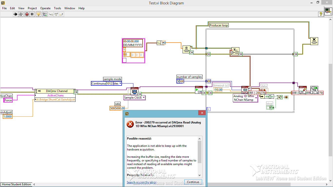
Code error-200279 for data acquisition
Hi all
I am trying to build a small program of data acquisition, but I get a 200279 error telling me to increase the buffertime. What I am doing wrong?
Andersson wrote:
No, you're right. I don't get the error, I turn off highlight execution.
It seems so. I did not understand why he would come with an error during the audit of the code with the bulb. It seems like what I discovered on www.ni, one can avoid the error of initialization of certain data for the chart.
Not sure if I got it 100% correct however. Here is the link:
http://digital.NI.com/public.nsf/allkb/A647A1BE3DA8336786257AAA0066B45B
I don't have any other loop in the installer. I'm sorry for the confusion with the name 'producer loop. It's the only loop in the code, I deleted the rest to refine the error.
Is the conclusion that the program is good? Or do I have to do something to remove the error?
The table has nothing to do with your error. It's strictly highlight execution.
When you configure a continuous sampling, start the collection of data at a given flow rate. It is so big a configuration of the buffer. There is an article that tells how much room it is exactly, but for the sake of argument, let's say 10 seconds worth of data. In normal execution, your code runs pretty quickly that she is able to empty the buffer as soon as the data are acquired. But when you enable execution of climax, your VI slows down to a crawl so that he can show that you step by step what is happening on each wire. Your data acquisition always occurs in the background. Execution of idle is to take much longer that data are acquired. Within one or more loop iterations, you have filled the buffer and get the error message.
You cannot use point culminating performance when you use a device of data acquisition in this way (or VISA ports either) where data are sent continuously at a speed that is independent of speed, the code is executed.
-
Using the SMU-6368 module, I would like to monitor the analog signal on multiple channels and trigger on several channels - relaxation and acquisition channels is all on the same device. Probably going to be sampling at 200 kHz and more. FM LV 2009 2012, with SV toolkit in Windows 7.
If SW trigger is the only way to follow, there example code shows how to manage the block size, etc.. ?
jkessler,
Yes, the example was in 2012. I didn't get what you asked for in your first post because I didn't know you wanted to ANY channel to trigger acquisition of all channels. It is not possible at the hardware level, because you cannot specify four channels as the command source. This will be implemented in the software. I recommend the reading of all four channels and neglecting data until you determine that one of the channels reached your threshold value.
Kind regards
-
Hello
I have been to
CREATE or REPLACE TYPE event_msg_type () AS OBJECT
name VARCHAR2 (10),
current_status NUMBER (5),
next_status NUMBER (5)
);
I need deque spacific data using DBMS_AQ.dequeue, which means, for example, I need to wait where name = 'hh '.
BRYou have a few options, I can think... more I'm sure:
1. the use of the rules - so when a message is queued, the rule evaluates the content and correctly sets the consumer_name, then you could have a rule that a for name = "HH" and then put that, under the HH consumer_name - take a look on: http://download.oracle.com/docs/cd/B19306_01/server.102/b14257/aq_admin.htm#sthref945
2 DQ message by msg_id(2) - so ask the queue view, interrogatin field user_data for these messages matching your criteria get the msg_id(2) argument and use it to DQ them.
I prefer option 1.
HTH
Thank you
Paul -
Using the Serial Port for data acquisition Non-Serial
I searched the forums and can't find anything on this topic.
I saw that it was possible to use the parallel port for e/s digital single and I was hoping that the serial port can be configured the same. It seems all VI VISA only to use the serial port to receive ASCII characters at a given flow rate, but is it possible to simply query the status of the line series at my own speed to see if it is high or low, kind of like a single pin DAQ?
It seems that it would be possible until the serial data are read and controlled by labview, not Windows. Let me know if you have ideas of how to approach this problem, or any comment as to why it is not possible.
Thank you all!
Select the property > settings series > Modem of the line parameters. For example, the State of the CTS is an entry to the pc.
With the help of these lines is a very poor substitute for a scope or map DAQ. The only things you can return is Asserted, Unknown or Unasserted. The range of acceptable signals is important enough. Anything between + 3 and -3 is an unknown state. Your other signals is + / 3 to 15 volts. What type of signals do you really want to capture?
Edit: there is no such thing as a visa so I have no idea of what you actually use.
-
Write equations on the front for data acquisition
Hello
I was wondering if its possible while a VI is running for:
- Write an equation custom on the façade.
- Use the equation on data acquired since the VI is running.
- Draw the calculated data.
See you soon
I think you should take a look at the examples (help > find example... > tab "search" > try with formula or equation), it is one that shows in a simple way, look here: C:\Program NIUninstaller Instruments\LabVIEW 2011\Examples\measure\maxmpl.llb\Waveform Formula.vi using generation
hope this helps
-
Dear all brothers.
I want a query to retrieve the data sheets for employees, as the start_date and end_date, leave_type arguments pending these things.
Thank you in advance, I appreciate your help.Hello
Hope under query allows to obtain information on pending leaves: -.
Select Papf.employee_number 'No. Emp'
, papf.full_name "name of the Emp.
, hat.creation_date 'let applied '.
,(Select Fu.user_name from)
Apps.fnd_user fu
When user_id = hat.last_updated_by) "last approver.
, decode (hat.status, 'E', 'pending approval', 'Error', ' there 'would be', 'Deleted', 'Other') 'current state '.
, hat.item_key, 'key '.
, hats.information1 'Absence Start Date.
hats.information2 'Absence End Date'
(by selecting paat.name in apps.per_absence_attendance_types PAAT
where absence_attendance_type_id = hats.information5) Type "Absence".
, hats.information6 "without category".
hats.information9 'Status of Absence'
of apps.hr_api_transactions hat
apps.hr_api_transaction_steps hats
apps.per_all_people_f women's wear
where 1 = 1
and papf.person_id = hat.selected_person_id
and hat.transaction_id = hats.transaction_id
and hat.status = 'Y '.Thank you
Avinash -
I had to reload our installation of LV and have lv2011 and NOR-DAQMX 9.9. I can't get the range of DAQ function to display the toolbar funtioon. I tried to fix the OR-DAQMX driver. It showed message "installation lv2012 support" and "facility charge SP1 lv2012". I have not seen a message of support from lv2011.
There was a problem downloading of configuration and 2012SP1 was wrong as my group of licenses for the account representative. This has since been uninstalled before installing 2011 (without SP1).
Thanks in advance,
Bill
Updated the installation of the driver NOR-DAQMx vs repair. Apparently, he saw the LV2011 and installed support files. Everything works now.
-
OPERATING SYSTEM: AIX
DB: 11g
In a physical configuration of the standby database, I had to perform incomplete recovery to my primary database and because of that I had to open my primary database with resetlogs option.
What should I do with the database of the previous day, I need to create another as the orde of my primary is reset with the LSN 1?
ConcerningWhen STANDBY_FILE_MANAGEMENT is set to manual on standby and you add a data file to the primary, then the data file is created in Eve DB under the $ORACLE_HOME/dbs location when the redo data is shipped from primary to standby mode. And finally, the MRP stops.
You can check the link I gave in my previous post.If redo data are not delivered before primary and you do not get to see the data file newly added in the standby database using the view v$ datafile, then you will need to place the tablespace in primary DB in backup mode, copy the data from database pending file and update the controlfile ensures.
Re: Lost datafile on Standby in Oracle 10g
Kind regards
Shivananda -
How to run a window of data acquisition and another pane at the same time
Hello
I have a main window for data acquisition and in front panel there are four Sub Vi. When the main window of data acquisition is running and at the same time if I run the Subvi - main window stops data acquisition and the secondary window starts to run. But I want to launch the window of acquisition of primary data and the pane at the same time. Please give me a solution for this...
Thanking in advance.
Nikhil
Hi Nikhil,
My explanation has answered your question. Take a look at the image as an attachment. Let us know if you have any other questions.
-
standalone application for the acquisition of data using the NI DAQ card
I did a stand-alone application in labview GUI for data acquisition and processing of the signal. If I have to run this application in any other computer which should be all installed software other than the labview runtime engine... CD DEVICE DRIVERS OR alone must be installed or do I have to install any other software of data acquisition using the data acquisition card OR?
Thanks and greetings
You need only the racing of the engine, the device for the device drivers, maybe need pilots VISA if you make serial or something of this nature, you may need the channels or tasks created in the measures OR and automation if you created the it.
There may be other things you'll need depending on what you include in your code and what tool kits that you have installed.
-
GSS stuck "waiting for configuration data.
One of my clients have 2 GSS 4900 running ver 4.1 (1)
I can't get the ESG service works properly in a secondary gssm running. Gssm service looks like it starts but if I check "gss status" och "Show System State" that it is awaiting configuration data
MNT - GSS - 002.nt.se #show - system status
Standby GSS - 4.1 (1) GSSM - Cisco [Mar 12 Nov 16:10:21 UTC 2013]
Recorded in primary GSSM: 10.16.0.15
Component waiting for data routing configuration (wait a minute). [runmode = 3]
START THE SERVER
16:01 Config agent (crdirector)
16:01 Config Server (crm)
16:01 Database
16:01 GUI Server (tomcat)
16:01, Node Manager
16:01 webserver (apache)
Ping works fine between the GSS: are and there is no firewall involved (both are located on the same ip subnet).
I did stop gss and then start gss. Waited for 24 hours, but the situation is the same.
If I'm running tcpdump on the secondary, I see TCP traffic and UDP between the primary and the secondary, although all UDP packets have a warning of incorrect checksum.
I have no idea on how to t-shoot, that. Should I do gss disable, remove this gss of the primary gssm and enable gss again in the secondary?
Notice to lovers?
Hello
There seems to be a communication problem. You can do the following and see if the GSS is going to runmode = 5.
On the standby: gss stop gss disable Then, go into the GUI of the GSSM and delete the standby GSS from the resources tab Then go to standby: gss enable gssm-standby x.x.x.x (IP of primary )
Then in the GUI of primary GSSM, you will again see the standby in the resources tab. Click on it, and check on the activate button, then hit submit. Make sure the standby goes to runmode 5 under "gss status" output.
If this doesn't work then you can try the below:
Go to the GUI of the GSSM and delete the standby GSS from the resources tab. On the standby: gss stop restore-factory-defaults Make sure you have a console connection so you can do the initial config on the Standby GSS (add IP, etc). Once done, enter standby:
gss enable gssm-standby x.x.x.x Then in the GUI of primary GSSM, you will again see the standby in the  resources tab.
Click on it, and check on the activate button, then hit submit. Make sure the standby goes to runmode 5.
Kind regards
Kanwal
-
Problem of reliability data acquisition PXI-4071
Hello
I'm having a problem of reliability using my 4071 Pxi digitizer mode.
I have a number of tests that use the SMU-6363 (usually configured for DC) analog output to provide a stimulus for our own device, which has a number of a/d converters. We use the PXI system for calibration and testing.
1. I select a voltage ranging from tensions.
2. program the PXI-6363 to drive this tension
3 TIME about 10ms to settle. Note there no discrete capacitors or resistors in the circuit. Everything is parasitic and would generally be under the nF mark and less than 10 ohms
3. configure and Initiate() acquisition of data with the PXI-4071. In general, I use a sample rate of 1000 s/s and get about 30 samples (worth 30 ms). Activation is immediate and I used the default a queue time, 0, set the time and it doesn't seem to make a difference.
4. measure the voltage with the CDA. For debugging purposes I have sometimes made twice once before calling Initiate() and once after. The after is normal. The time required to measure the ADC is shorter than the acquisition time, but regardless of stimulation by the SMU-6363 is constant
5. extract the waveform.
6. the average waveform and compare the value of ADC measured by applying tolerances etc.
Here's the problem: it works well most of the time. But only 0.1% of the time (1 on an acquisition of 1000), I get 8-12 samples that are close to 0. It sounds like a problem of time settling (on the surface), but no matter the amount of wait time data, I always get this behavior. Not only that, but the tension before the call to Initiate() in height CDA, it always confirms that the motor voltage is already set to the programmed value. Nevertheless the acquisition presents near data 0.
So far our independent ADC always reports the expected before and during acquisition (100%) voltage. It's like the DMM input is disconnected during the acquisition during a period of time, because we have confirmed that the voltage is already present prior to the acquisition (component can). I have no errors the insider or FetchWaveForm calls. I still have all my samples. And 99.9% of the time that everything works as expected.
The DMM and ADC are connected to the same point and both are referenced to ground, and as I said before only the parasitic capacitance and resistance (cable). We use a matrix of switching (PXI-2530 (b) to make these connections. We almost always use 51/2 digits and 10V range for data acquisition.
Hello
I thought about it and was going to repost but am distracted.
The device with the ADC also has a mux and switches the mux to an internal node. It only switches when measuring and is open at other times. There is a race condition where the acquisition starts too early and maintains the acquisition after that the switch is open. Unfortunately I don't have the option to trigger.
I forgot the internal mux that I had designed the test years ago and I did some updates to improve the stability of the test. That's why we start the ADC measurement when acquiring.
I just added a routine to reject samples below a threshold
Maybe you are looking for
-
I made an update of the system to the original settings and everything seems to go as usual. While performiong the many windows updates, I noticed that the battery indicator indicates "no battery installed. I found a few solutions dealing with this
-
Satellite A300/A300D Webcam problems
Hey sorry if this question was asked before, up to what recently worked my webcams recently I get the following error message *'Web fail open driver. Restart the computer or the camera '. * I tried to do both and no result, I wondered if anyone has h
-
E5 - 572 G-5577 cannot function properly 840M 2 GB dedicated VRAM nvidia
Hi, I recently bought Acer aspire model E15 E5 - 572 G-5577, which came with i5 - 4210 m (2.6 to 3.2 Ghz), 8 GB of RAM, Nvidia GeForce 840 M 2 GB dedicated VRAM, 1 TB HDD and freeDOS. Since Win8.1 x 64, I received for my birthday, I bought this lapto
-
Anyone know what's the difference between Illustrator and Photoshop sketch to draw?
Hi, I'm new to both apps and I am trying to determine if it would be worth having two apps on my tablet. Someone uses both, and if so, what situations do you use for?
-
I built an application of web service in Jdeveloper 11.1.1.7 to be used by other clients. Just the General steps as follows (Server web service Application is generated--> deployed on the server-> used by clients with the location of the WSDL file).N