Write equations on the front for data acquisition
Hello
I was wondering if its possible while a VI is running for:
- Write an equation custom on the façade.
- Use the equation on data acquired since the VI is running.
- Draw the calculated data.
See you soon
I think you should take a look at the examples (help > find example... > tab "search" > try with formula or equation), it is one that shows in a simple way, look here: C:\Program NIUninstaller Instruments\LabVIEW 2011\Examples\measure\maxmpl.llb\Waveform Formula.vi using generation
hope this helps
Tags: NI Software
Similar Questions
-
choice of the model of design for data acquisition system
Hi all
I have a problem on the selection of the model design / architecture for a data acquisition system.
Here are the details of the desired system:
There are data acquisition hardware and I need to use by looking at the settings on the user interface.
the period of data acquisition, channel list to analyze must be selected on the user interface. In addition, there are many interactions with the user interface. for example if the user selects a channel to add scanlist, I need to activate and make it visible to others on the user interface.
When the user completes the channel selection, then he will press the button to start the data acquisition. Then, I also need to show the values scanned on a graph in real time and save them in a txt file.
I know that I can not use producer consumer model here. because the data acquisition loop should wait for the settings to scan channels. and it works on a given period by the user. If the loop of user interface makes higher then loop (loop data acquisition) of consumption. This means that queue will be bigger, larger. If I use notifier this will be some data loss comes from the user interface.
y at - it an idea about it? is there any model of design suitable for this case?
Thanks in advance
Best regards
Veli BAYAR
Software for embedded systems and hardware engineer
Veli,
I recommend the model producer/consumer with some modifications.
You might need three loops. I can't tell for sure from your brief description.
The loop of the User Interface responds to the user for configuration entries and start/stop of acquisition. The parameters and commands are passed to the Data Acquisition loop via a queue. In this loop is a machine States that slowed, Configuration, Acquisition and stop States (and perhaps others). The data is sent to the processing loop through another line. The processing loop performs any data processing, displays the data from the user, and records to file. A registrant can be used to send the Stop command or stop the loop of the UI for other loops. If the amount of treatment is minimal and the time of writing files are not too long, the functions of processing loop might be able to happen in the case of the UI loop timeout structure of the event. This makes things a little easier, but is not as flexible when changes need to be made.
I'm not sure that there is a type of design for this exact configuration, but it is essentially a combination of the models Design of producer/consumer (data) and producer/consumer (events).
Lynn
-
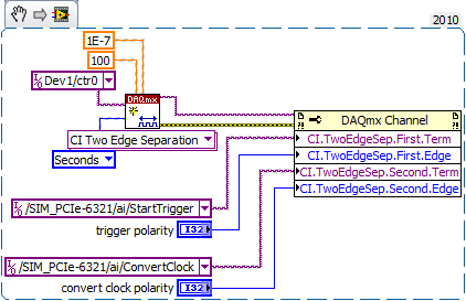
delay between the trigger and data acquisition
Hi, I use NI SMU-6368 as a tool for data acquisition. In my experience, I use an external digital trigger to start taking measures of a thermistor.
However, before the experience, I want to know the time that elapses between the detection of the trigger signal and data acquisition start time.
Is there a way to do this?
Here's the kind of thing I configure to get an accurate measure of time of t = 0 trigger signal to the
the actual first A/D conversion. It may be too much for a measurement of the temperature, but you should get
the right track.
-Kevin P
-
Create a button on the front for the diagram
Hello
I am looking to create a button on the front for the diagram.
Is this possible? If so, how?
Thank you!
-
TDMS write a comment in the middle of Data Acquisition
Hello
I am currently using TDMS for my data record. Currently I log data from a Keithley module via GPIB connector.
Essentially, I want to save data in intervals and during the recording of data, I want to have a comment section where I can write the changes that have been made.
It connects every minute and I want to add a comment in the minute 5 for example. What is the right way to apply it.
Thank you
I would use a loop that is dedicated to writing in the PDM file. You can then send commands/data to this loop in a queue. You could a single command to write your DAQ data and another for observational data. I would connect all the data data acquisition in a group and observational data in a second group. That will make your file much easier to understand.
-
Configuration of the two of the same model data acquisition
Hello, community of NOR.
I'm an intern in mechanical engineering with experience in base with LabVIEW.
I would like to speak to OR directly on this issue, but I don't have a service contract and my company wants me to understand this before you buy LabVIEW.
I hope that someone has experience about my question, and I would be very happy to help.
We intend on purchasing an expansion card for our acquisition of data (OMB-USB-2416), but unfortunately it is offline and no custom would not happen in time.
So, I need LabVIEW to read voltage HAVE two of the same model of data acquisition, which would amount to about 30 channels.
Is this possible with LabVIEW?
Thank you.
Measurement computing says that the "physical channels" dropdown list is automatically filled in once both devices are configured.
-
How to increase the speed of data acquisition?
Hey, currently I using 6210 OR of data acquisition and control switch. I used labview to periodically check the 7 switches and read data from 7 channels in the meantime (1 sample on request). I ran 70 loops for 10 groups of data, the cost of the time looked like 2.2 seconds.
I would like to end a 700 loops in 2 seconds, is it possible to improve?
Thank you
PEM
Look at the Terminal stop of the DAQ Assistant Express VI. You are starting and stopping of the task for the acquisition of data on each iteration of the loop.
Starting from the help file:
Stop
Specifies to stop the task and release device resources when this Express VI ends execution. For ongoing tasks, this entry is FALSE by default, which means that the task is running until the application terminates. To stop the task, you can use the device again in the same application, wire control wire you the Conditional stop this entry to the same terminal of the while loop. For single-point and finished tasks, this entry is TRUE by default, which means work stoppages after all samples are acquired. To optimize the performance of single point when using this Express VI into a loop, wire control wire you the Conditional stop this entry to the same terminal of the while loop.
Also from the help file:
Continuous single point of entry or exit, the of VI Express DAQ Assistant cannot allow optimal operation. See Acq & chart voltage-Single Point optimization VI in examples\DAQmx\Analog In\Measure Voltage.llb for an example of techniques to create more powerful applications, single point of I/O.
-
the relay control data acquisition
I am creating a vi that controls (press and release) several relay using a USB 6501 data acquisition. This should be a task relativily easy but I get flumoxed by errors. I tried to use the examples, but I get an error telling me that I need to use the mode of generation 1 sample (on request). Help, please
Sure. The easiest way is to have a DAQmx writing followed by a function of delay, followed by another entry, followed by another period. Simply plug the error links in order to control the flow of data. However, the VI would be insensitive so you can use a state machine or function elapsed time so that the VI can be stopped without waiting for waiting for him at the end.
-
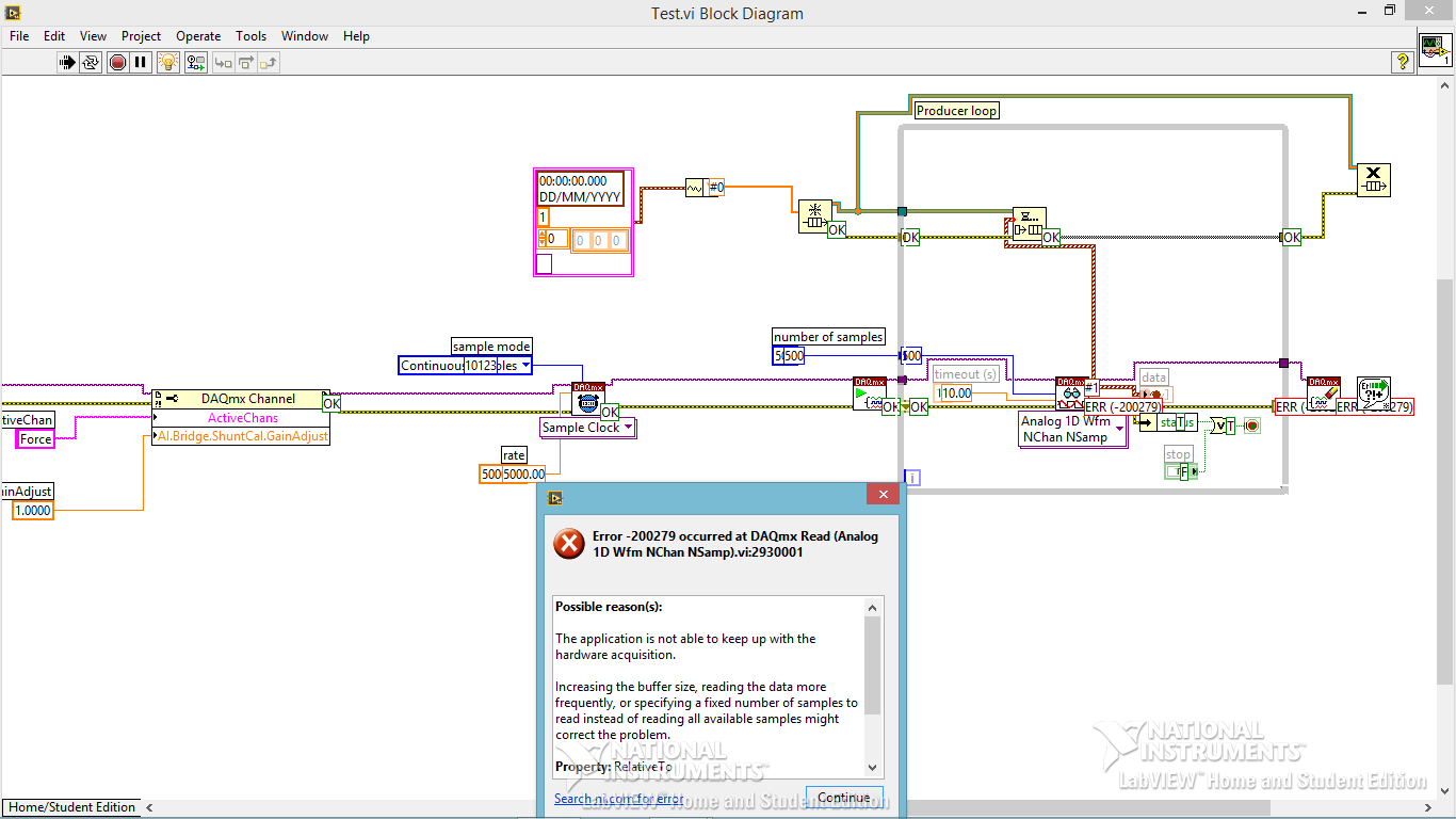
Code error-200279 for data acquisition
Hi all
I am trying to build a small program of data acquisition, but I get a 200279 error telling me to increase the buffertime. What I am doing wrong?
Andersson wrote:
No, you're right. I don't get the error, I turn off highlight execution.
It seems so. I did not understand why he would come with an error during the audit of the code with the bulb. It seems like what I discovered on www.ni, one can avoid the error of initialization of certain data for the chart.
Not sure if I got it 100% correct however. Here is the link:
http://digital.NI.com/public.nsf/allkb/A647A1BE3DA8336786257AAA0066B45B
I don't have any other loop in the installer. I'm sorry for the confusion with the name 'producer loop. It's the only loop in the code, I deleted the rest to refine the error.
Is the conclusion that the program is good? Or do I have to do something to remove the error?
The table has nothing to do with your error. It's strictly highlight execution.
When you configure a continuous sampling, start the collection of data at a given flow rate. It is so big a configuration of the buffer. There is an article that tells how much room it is exactly, but for the sake of argument, let's say 10 seconds worth of data. In normal execution, your code runs pretty quickly that she is able to empty the buffer as soon as the data are acquired. But when you enable execution of climax, your VI slows down to a crawl so that he can show that you step by step what is happening on each wire. Your data acquisition always occurs in the background. Execution of idle is to take much longer that data are acquired. Within one or more loop iterations, you have filled the buffer and get the error message.
You cannot use point culminating performance when you use a device of data acquisition in this way (or VISA ports either) where data are sent continuously at a speed that is independent of speed, the code is executed.
-
BNC-2110, 6023E PCI card and Labview V9.0: sensitivity of data acquisition (change more little detectable voltage) is 0.002V
Hi, I use the software/hardware above to read a voltage of a potentiostat world Precision Instruments No..
I'm trying to record changes in voltage as low as 0.0003V but using the wizard DAQ, I seem to be limited to a sensitivity of 0.002V. This is the limit of real sensitivity or have I missed something?
Any help would be greatly appreciated.
Hi DCAM77,
Thanks for joining the forums!

The PCI or 6023E has a 12-bit ADC. In other words, it can make the difference between 4096 (2 ^ 12) different levels within the range of cards. The card you have has a selectable range by ± 10 V, ± 5 V, ± 500 mV or ±50 mV software.
This means that the minimum detectable variation will be 4 mV, 20 mV, 244 µV or 24, depending on the chosen range µV.
You should be able to use the ± 500 mV or ±50 mV to get the least significant bit (LSB) value, you need, even if it means that your signal is located between these values. If not, then you need to consider other materials to the application, or the addition of external circuits across the signal.
-
The reading of data acquisition via tcp
Hello
I am building an application that controls an acquisition of data via tcp.
I have a JAVA program that communicate with labview, give a command and data acquisition starts. (So, I read the correct Java data at Labview)
My problem is if I try to read data acquired by data acquisition (continuous sample 1 k samples), I've read strange values.
I transform of double values in the string and send it via tcp.
How can I read it in Java? What type of socket should I use? What is a rate problem?
I also tried to transform small/big-endian byte order, but it does not work.I enclose a sketch of this part of the application.
Please help me, I try for 2 weeks!
Thank you all...I find the solution in the lavag forum.
I post here, if it can help someone.http://lavag.org/topic/16359-sending-LabVIEW-data-via-TCP/page__pid__99983#entry99983
-
Is it possible to change the name of data acquisition device?
Hi all
Is it possible to change the name of device of data acquisition in a pragmatic way?
I wish I had at the beginning, when I start the data acquisition control a name that my .net program assigns to the DAQ card. Is this possible?
Thank you
Virginia
Ashly thanks!
Virginia
-
the scale of data acquisition and data entry error
I have a USB 6211 camera set to MAX for 11 different channels: the first 10 channels are configured with a scale factor of 2 while the last channel is configured with a scale of 1. I connected battery 9 V for the first two channels, ai0 & ai1, (level 2) and the last channel, AL10, (1 scale). The input pins were 15, 17 and 20 for input voltage with pin 28 connected as a reason. Then, I checked the feature in MAX. Surprise! I expected to see 18 volts for the first two channels and 9 volts for the last channel, but much to my surprise I got all channels showing data about 10.86 volts and the last channel showing a value of 7.79 volts! How is it that I see the values for channels not connected! In addition, why are values of cable channels so screwed up! With a 9 V battery and a scale of 2, I expect to see 18 volts, not of 10.86, and where the 7.79 volts for the channel which has a scale of 1! If I run MAX continuous mode instead of the sample N mode I get a few other strange results: I get a single horizontal line and 1 sinewave! It's amazing because I have a 9 volt battery connected to the unit! I don't even how arrays of the VI that uses these signals is like since they are all screwed. Will you please advise me on this one because I'm completely stumped.
-
Oracle will consider the creation of a day 2 hands on the documentation for Data Guard?
Hello
Oracle will consider the creation of a documentation of son of hands 2 day for Data Guard?
There is already an OTN 2 day of CARS and performance tuning documentation.
Thank you
Updated - she sent the link to this topic for the Product Manager Data Guard. As a result, Oracle may or may not consider creating 2 days hands on Data Guard documentation, but no doubt they consider at least considering creation day 2 hands on the Data Guard documentation.
-
Can not find the plugin for data recovery?
Hi guys,.
I don't have the time to investigate this, but I was wondering if you can get started me.
I installed vCenter4 and have only 1 host ESX 4 up to now (ESX4i).
I attributed an enterprise of this machine license.
I can't see the plugin for recovering data anywhere in my vCenter.
What Miss me?
I'm going through the documentation as we speak. Thank you
Please consider my response as 'useful' or 'proper' markingHave you downloaded vDR from the download page where you went to get vCenter/ESX 4.0? Once installed, you will need to go to the Plug-ins and download/activate the plugin. This is at least the case for VCB, VUM, etc..
=========================================================================
William Lam
VMware vExpert 2009
Scripts for VMware ESX/ESXi and resources at: http://engineering.ucsb.edu/~duonglt/vmware/
VMware Code Central - Scripts/code samples for developers and administrators
If you find this information useful, please give points to "correct" or "useful".
Maybe you are looking for
-
...
-
Adding Photos to the contacts list
How to add photos to my contacts list?
-
Try to unpack a file open to dozens of windows
Original title: Winzip! Hi again Once again needing help. I don't have Winzip on my pc, so I had trouble opening zip files. Another kind person told me how to fix it, and I click with the right button on the files, select extract and get a 'folder '.
-
installation of XW4300 Windows 7 64 bit
Hi all We strive to Win 7 64 bit version on the workstation xw4300. Everything's fine until it finalizes the installtion and installing the drivers, then the system stops with a parity error. I was wondering if anyone has successfully done this facil
-
Install the older version of paint
Paint Now I have Windows 7, which includes the new version of paint. I love the new version and install the old version of paint on my new Windows 7 XP. How can I do? Thank you.