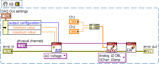
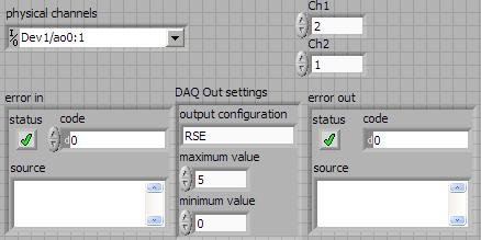
Acquisition of multiple simultaneous analog output data
Hello, I'm doing a program when a user telnet to my computer and labview will recevie provided cn and analyze. then, he deciphers the emssage find what analog output it trying to change and then change it. I all the work, but I get error 50103 who say I can't have 2 screws DAQ assistant express running simultaneously. I want to have 2 different signals on A0 and A1 on my surfboard USB-6281. Is this possible? Thanks in advance. BTW im using labview 8.2
The vi in LV2009 is attached. I did the mods I had described. It should be a beginning. Modify if needed.
Tags: NI Software
Similar Questions
-
Several simultaneous analog output channels
I use DAQmx-NOR-USB.
I want to simultaneously generate two analog output signals, i.e. change the two outputs at the same time.
Simple example:
What is happening is that instead of two outputs simultaneous modification, there is 1mS delay:
I want to generate premium output, using two channels, but the delayed response is not acceptable.
Any suggestions?
Hi Seth B,.
Yes, it works!
A note: to make visible this property, I had to turn on "display all the attributes" in the menu "Select filter" (right click on the node property).
Thank you.
-
the time of acquisition of data - how to calculate the rate of analog output
I want to calculate an acceptable rate of analog output, one that is taken in charge by material (PCIe6353), without the rate being changed by the VI DAQmx Timing (sample clock). The final objective is to have a rate of analog output that is an integer multiple of the analog input for precise frequency, since the sinusoid AO's amplifiers, which have a ringtone when AO updates occur.
According to 27R8Q3YF of the knowledge base: how the actual scanning speed is determined when I specify the rate of scanning to My d..., the rate is revised as needed by calculating the rate of clock / asked for advice, divide the result rounded downwards and upwards in the clock of the Board and use the one that is closest to the requested speed.
If 'Embedded clock' is selected, which is the result "Council clock. DAQmx sample clock timebase Timing node - SampClk.Timebase.Rate says 100 ms/s. However, for a rate resulting from the update of 2.38095MS / s, the divisor of the time base timing node - "SampClk.TimebaseDiv" gives a value of 42. 42 x 2.38095 M = 99, 999, 990, where it should be 100 ms/s.
How to calculate an acceptable rate of analog output is supported by the hardware? I have other plates, in addition, a general method would be appreciated.
I haven't worked all the details yet but noticed a few things that may be relevant.
Req AI rate isn't a whole ditch 1E8. It is used to determine the rate of the AO.
There is no check to ensure that the rate of the AO is an integer division.
It seems that you have the right idea, but the implementation is not yet there.
Lynn
-
Outputs audio multiple simultaneous sessions in windows 7
I've seen several questions about activation output audio at the same time multiple in windows vista and 7, as example SPDIF and analog output, answer every time, it's that this is not supported by windows 7. Why is this? Why isn't there it worked fine under XP, support could you guys give some details, why is not supported more?
Virtual Audio Cable - solved my problem
-
Analog acquisition and digital simultaneous DAQmx
Hi all
I use the USB-6212 acquisition card to acquire analog and digital inputs. However, I encountered some problems that I don't know how to solve.
All channels (analog and digital input) is independent of one another, but should be acquired at the same time (using the same clock, I think), but I'm not managing to achieve; In addition, I can not put a task so that the digital acquisition is made by "continuous sample" - the error says it is not supported, but I saw this configuration in other examples in this forum.
The only way to get a digital waveform must keep pooling the entry? And, therefore, also in common analog input? Is it not this costly approach from the point of view resources?
Best regards
The decrease of performance will be determined by the speed of your computer and your USB hub.
I think that to get the hardware timing of digital I/o on a USB device, you're going to have to step up to a card in the X series as the 6341, but I'm not sure about this. You can find this specification under the specifications of each product tab. Looking for 'Material' under DIO > Timing.
-
How to write constantly to analog output and read from analog inputs
Hi all -
I had a question about writing continuously to analog output reading simultaneously an analog input.
It's my first time to post a message to the community, so please let me know if I made mistakes.
I use Labview 2011 with a NEITHER-DAQ USB 6215.
I'm looking to generate a waveform and write it continuously in an analog output. It is then connected to an entry on the acquisition of data, where I am trying to sample the analog signal. (I realize, there is a system of trivial, but I'm hoping to build on it once I have run).
The task of reading from the analog input works fine, as I tested it in several other cases. I have a problem writing to the analog output.
For this task, I tried to follow the "Gen Cont Wfm Clck Int' VI to generate the wave form and start the task. I then try to write to the output of the analog timed loop. However, it does not seem to transmit a signal and doesn't give me any errors.
I have attached the VI but also a screenshot.
Please let me know if anyone has any ideas. I would really appreciate the help!
Thank you
Peter Borgstrom
We will review your tasks one at a time. First of all, the task of generation/Analog output Waveform. Generate you a waveform (I'm unsure of your VI if it is a fixed waveform or not) and send it to a defined output function to produce a waveform continuously, using N-channel and samples of N (where you set not these previously). You should not put this inside has timed loop, as the DAQ hardware has its own clock - if you simply put it in a while loop (with a stop to break out of the loop), the loop will call the function for the first points of N, wait until all N have been taken out, then call it again to another N points (up to what you press Stop).
Now, suppose that you have the output connected to a load voltage (say a decent resistance). You can wire the input terminals of your A/D converter through the same load and set up a similar analog input loop, running in parallel (i.e. in its own independent of the OD loop, while loop). You pourriez start together (with, say, a merged error since the initialization code line loops HAVE and AO become lines of error in "loops of sampling" described above), but you might want to delay loop (a little) the AI so that the OD has a chance to set the voltage before the bed.
I hope this helps.
BS
-
Hello
My question is about the analog output (0 - 10V) of the myDAQ unit.
On the card, you can read:
"Overdrive Protection +-16 V forever."
Lets imagine the worst case: 0 V output DQA, but outside a battery or anything else is connected with 15 V to the analog output.
Fact an "unlimited" current in data acquisition or protection 'Overdrive' works here and the material is safe to destroy?
The background: I want to OD are protected from transient voltages and toilet on a simple zener diodes clip or a tvs diode...
Thank you all, Markus
Markus,
To use a zener diode as protection, you must also have an impedance of current limiting in series with the source against which you are protecting. The manual for the device of maDAQ indicates that the lines of the AO are pushed by OPA1642 op amps. TI the MSDS for this unit shows the current limiting internal ~ 36 my short circuit with Earth and a thermal shutdown circuit that tries to protect against the terms of overpwer.
However, under your 15 V battery, 11 V zener and 0 V programmed DAQ exit, the situation may be different. The current from the battery through the zener will be limited by the impedance of cables or any type of resistance on the line. This has no direct effect on the myDAQ device, but it will probably destroy the zener unless resistance limits the current to a lower maximum current nominal zener. As long as the voltage at the output of the myDAQ is lower than the internal supply voltage (+/-15 V), on the OPA1642 current limitation should apply. With 11V applied to the output and the value set to zero the device would probably be to try to sink the maximum current for-15 V power supply. Which translates to a dissipation of power of more than 900 mW, which exceeds the rated capacity of the op amp. Themal protection should, in principle, reduce the current to a level that does not exceed the thermal limit under development.
This test can be a costly process. The unit may be destroyed. Given that the maximum current specified for an analog output channel is 2 my and the maximum voltage is 10 V, I would consider a series resistance of perhaps 1000 ohms and clamping schottky diodes at the + 15 V and - 15 V power supply. This will limit the current to 10-20 my in all conditions you have mentioned and would also provide protection to the case where the battery is connected the myDAQ device is turned off. He alsoe does not care about the polarity of the external source. It will drop the output voltage according to the load impedance. If this should be used in a student lab, the calcualtion of this decline is something they should be doing anyway, and would be a small price to pay for protection.
Lynn
-
How to send a pulse only to analog output
I send a function rect through to the ao, thorugh the transmitter transducer, then a receiving transducer through AI. Although I'm kind of a signal, I can see that there is something wrong. What I think is happening, is that the pulse is transmitted continuously while I want it to be sent once. of the received signal, waiting for the signal to reach 0.2/1500 s as the medium is 0.2 m in diameter and the speed of the sound probagation through it is around 1500 m/s. So, with these considerations, I have the following questions:
1. How can I configure the wizard daq output to send only 1 rect function
2. read permanently or for a period of time
I have attached the output and input along with a photo of my VI signals
Thank you
Hi Macane,
For a unique configuration of generation/acquisition, you would set your DAQ Assistant to finish instead of continuous and calculate how many samples is your only impulse you send. For the acquisition, you can configure a finite acquisition of trigger reference analog where it will begin to capture after your signal is received, or if you do not want a triggered acquisition, you can set the number of samples to acquire. For example, finished task sampled at 1 kHz to 2000 samples would correspond to a second acquisition 2.
You can configure all the wizards within the express VI data acquisition by double-clicking the VI. I hope all goes well!
-
Analog outputs with different time scales
I use products AO of a card PCI-6731 for an application scan head and I have some difficulties to achieve peak performance, that I need. I am contolling the map with nidaqmx drivers in c ++
Basically, an output controls scanning in the direction Y (which is a line of scanning and is very fast) and the other in the X (increment once per scan line, so much slower). The complication is that both exits start at an external trigger, because positioning is synchronized to a separate data acquisition card.
Now, what I do is:
-write the scanline for 0 output waveform
-set output 1 to a given position
-say next Trigger output card
-hangs at the end and stop tasks
What I really want to do, it is just tell him to start with on each external trigger output waveform of scanline 0 and output 1 increment to the next position. So I could do a complete 2D scanner with a minimum of control software.
Any ideas on how I could best achieve this? My understanding of the nidaqmx drivers I don't see an elegant way to do it.
I could potentially do some operations on the done callback, although it makes me a little nervous because the control PC running windows, it is not a real-time operating system.
Hmm I do not know exactly but there are a couple of things (it is close)...
The output frequency of meter in your example 5 MHz (20 MHz, 2 high ticks, weak 2 ticks), which is faster than holders 6731 for a sample clock. I thought that this would have given a material error... are you looking for errors once the task runs (for example using DAQmxIsTaskDone)?. There is a DAQmxCreateCOPulseChanFreq if you want to set the clock frequency directly (it will use the appropriate default internal time base).
The task of counter generates 1000 pulses per trigger, is what determines the number of samples generated by the trigger (I assume that you want it to be 1024 aka "numSamples").
The analog output task must either use:
(1) calendar continuous if the output will repeat indefinitely as several triggers are acquired.
(2) finishes pitch (N * numSamples) samples where N is the number of lines that you want to exit and numSamples is the number of samples per line. In this case, the task will end once the lines were triggered.
Best regards
-
analog output digital start trigger the api c
Hi, I'm trying to start analogue output based on a digital trigger (either PFIO or a PXI line) I can make this easy in LabVIEW. However with the C API (through the Python wrappers), the problem is when I call DAQmxBaseWriteAnalogF64, writing will always be timeout that the acquisition was not triggered. However, I can't call it after the trigger occurs, because obviously, it will be too late.
I can't find any examples of C API where the analog output is triggered a digital triggering. I can find for the analog input, but is fundamentally different that you can CONV read anytime after the trigger occurs.
Python code as follows (functions are equivalent ot C API, even if you have no need of ot pass the task handle such that it maintained as part of the Task object)
# create analog output task
analog_output = Task()
analog_output.CreateAOVoltageChan("Dev1/ao0","",-10.0,10.0, DAQmx_Val_Volts, None)
analog_output.CfgSampClkTiming("",outputRate, DAQmx_Val_Rising, DAQmx_Val_FiniteSamps, numSamples)
analog_output.CfgDigEdgeStartTrig("/Dev1/PFI0", DAQmx_Val_Rising)
analog_output.StartTask()
analog_output.WriteAnalogF64(numSampsPerChan=numSamples, autoStart=False,timeout=1.0, dataLayout=DAQmx_Val_GroupByChannel, writeArray=data, reserved=None, sampsPerChanWritten=byref(samplesWritten))print("Analog output: Wrote %d samples" % samplesWritten.value)# create digital trigger dig_out = Task()dig_out.CreateDOChan("Dev1/port0", "", DAQmx_Val_ChanForAllLines)

# create digital trigger function
highSamples = 1000
numpts = 3 * highSamples
doData = np.zeros((numpts,), dtype=np.uint32)
doData[highSamples:2*highSamples] =  2**32 - 1

# send digital trigger
doSamplesWritten = c_int32()
dig_out.WriteDigitalU32(numSampsPerChan=numpts, autoStart=True, timeout=1.0, dataLayout=DAQmx_Val_GroupByChannel, writeArray=doData, reserved=None, sampsPerChanWritten=byref(doSamplesWritten))
print("Digital output: Wrote %d samples" % doSamplesWritten.value)
Hi PatrickR,
You can review examples of code NI-DAQmx (ANSI C) text based on the production of an output using a trigger to start digital analog. If you included/checked support textual dusing your NI DAQmx driver installation, you can navigate to Windows start > all programs > National Instruments > NI DAQ > Teaxt-Based Code support > ANSI C examples > analog output > generate voltage > Mult Volt updates-Int Clk - Dig start. If you have questions/doubts about the material.
-
I am newbie in Labview... and it is very difficult to find good help and tutorials... it's really disappointing.
I want to find a good simple example of 'the analog output control "...
I found these 'words' somewhere on the internet in the file 'DAQBasic.pdf '.
It is mentioned I need 'VI' easy, but I can't find something like 'Easy VI' in the functions available.
There is far too much info anywhere and there is no structure...
How can I 'the analog output control "?
And please, I want simple examples...
Thank you!
Why spoil things by connecting the key to something?

Your code should be close to what you asked. You want to make sure that there is no case of timeout. I would use the event to change value instead of the key down. At startup, the acquisition of data code run once and then after that, wait key. A couple of different ways to fix this. Simply place the code for the acquisition of data inside the event.
-
Simple examples of analog output USB-6343
I've tried passing by 'find' examples and does not know how to find what I want.
I'm doing a simple analog output on a USB-6343. Examples of waveforms say they work with the USB-6343, but I really don't want a waveform, just analog of output does not exceed 10 Hz speed of renewal. Some of the more simple examples show that they work with the pcie-6343 but do not list USB-6343.
I worked with USB-6009 in the past, but when I try to use an analog output task that uses 1 sample on request, I get the error "not buffered operations clocked by the hardware are not supported for device and channel type.» Set the size of greater than 0 buffer, do not set up the timing of the sample clock or the value Type of sample On Demand time"
I tried samples N, 100 samples to write to 10 Hz - the same error. Samples of continuous - same error. 1-sample - timed HW - same error.
There is a series of examples of I/O for the X series? Is it possible to search the device examples rather than go through all the examples and by checking the list of devices individually?
Is 'size of the buffer' the 'writing samples"in MAX?
After contacting the support I was provided with the names of the more simple examples for analog i/o:
Analog output-Gen power Update.vi
Analog Input-Acq & chart voltage-Int Clk.vi
They are found in the getting started screen of
Click 'Find examples' near the lower right corner
Filter the results to material by clicking on the menu drop down for the material in the lower left corner and selecting USB-6343 (only connected equipment will be displayed)
Don't forget to check the box "limit results to material" below.
In the center pane, double-click 'Material Input and Output'
Double-click DAQmx
Path for the analog input - double-click Acq & chart analog measures - double click on tension - tension-Int Clk.vi
Double click on analog generation - double click on Power - Gen Update.vi of analog channel output voltage
The examples are for the single data point. Samples and exit multiples are produced by putting the writing or reading VI inside a loop. The beginning and the clear functions should be out of the loop.
Additional information, I need technical support was how material-filter results and identification of more simple examples which were not obvious from the examples of names.
-
Analog output of signal generation custom
Hello
I have a VI that generates a signal from the values in an excel worksheet. I'm trying this waveform through an acquisition of output data. I use a box NI USB-6211.
I copied the exit code for the acquisition of data from other VI that generates a sinusoidal signal coming from an excel worksheet. This program works very well. (attached for reference - Analog Output VI + sinusoidal waveform)
I have two problems at the moment. First of all, I get error-200560 about waiting until the function, attached.
Second output amounts only to about 5.5 v instead of 9V specified in the data.
My VI generate several types of waveform according to selected tests, but I'm trying to get an output DAQ working with the first test, named "disconnection of the battery" work first before implementing it in the other tests so please ignore others for now. To run this battery select VI disconnect under tests select then direct to the attached excel (BD values under 10V) file.
I hope that I myself have pretty much explained, otherwise please ask for more! I'm new to LabVIEW so your help would be very appreciated.
Thank you very much
Parker
aeParker wrote:
I've made a few improvements to the VI but I always feel the DAQ 5 Cap output, 5V.
Dear Parker,
I guess that this statement is based on the values in the chart show, AO 0. However, this is not (necessarily) the voltage produced by AO 0, but rather the tension being sampled by AI0. If you look at the DAQmx create channel for the AI voltage channel, you will see that you have left entries Maximum and Minimum Value unwired, which means that they take their values default to + 5v and - 5v. This may explain the behavior of cutting that you observe. Try the + 10 and -10 wiring and see if that solves this problem.
Bob Schor
-
Strange problem with analog output PCI 6251 and BNC-2110
I'm controlling current source of third parties using the connectors of analog output on my card PCI 6251 and BNC-2110.
The current source needs an input signal of 0.1V. I tested it using a battery, the potentiometer and the voltmeter, and by manually adjusting the voltage of power current works - current output with control voltage scales according to the specifications and is relatively stable.
The data acquisition card works too - when I connect a voltmeter to the AO0 AO1, the measured voltage corresponds to the target with great precision value.
But when I connect the current source of third AO0 AO1 data acquisition card, the measured output voltage drops and fluctuates. This applies to both channels of the AO.
I wonder what is the problem here. I suspect it could be a matter of the grounding - the current analog control of the source is an entry with two floating terminals differential. I tried to return the switches FS/GS on the BNC-2110, but that makes no difference.
Anyone knows similar behavior? Does anyone have any suggestions?
-
Recommendations for hardware OR with a minimum 6-channel analog output
Hello world.
Currently I have the NOR-device, USB-6009. However, it offers only up to 2 analog output channels. I'll need to have at least 6 channels of analog output. Therefore, can anyone recommend me any device OR that matches my needs (preference is the USB series)?
Kind regards
Jonathan
Did you go to the page data acquisition . You can use the different selection tools to narrow down your choices. Given that you have provided only a single parameter (number of channels), it is difficult to recommend anything. Determine what else you need (sample rate, voltage range, etc.) and you can call your sales engineer OR local and get all the help you need.
Maybe you are looking for
-
Could you enable the phone ask for a password before the switch off
Hello I just lost my phone and as it happened before that people know they have to just turn off immediately so that you'll never know where he was still. Would it be possible to remove all the actions of the lock screen as well as no one can turn it
-
Hello guys,. I asked the white list of our Circuit service (more on www.circuit.com)... https://Bugzilla.Mozilla.org/show_bug.cgi?id=1201832 I asked access more than 1 months ago but have yet to see any progress on this issue. No no not this white li
-
Tecra A10 - how to disable the fingerprint reader when it is docked
Hello I use a Tecra A10 with a 2 Express Port Replicator.How can I disable the fingerprint reader when it is docked and still use it when undocked? Thanks for your help
-
Count the instances of a value in a table of mutation
Hello I have a problem I can not effectively manage. I use a chassis with a group of surveillance of the modules and a 9474 cDAQ as a digital source of tension 9221 to run a high volume laboratory test. I am reading in a table Double 1 d of the value
-
I can't find an option to use my built in webcam
Hi I have a toshiba satellite pro laptop with built in webcam but I can't find any options to access Ive looked all over the laptop, but can not find anything to do with him or just not what I'm looking for tbh lol help wud be good! x [Moved from com