Simple examples of analog output USB-6343
I've tried passing by 'find' examples and does not know how to find what I want.
I'm doing a simple analog output on a USB-6343. Examples of waveforms say they work with the USB-6343, but I really don't want a waveform, just analog of output does not exceed 10 Hz speed of renewal. Some of the more simple examples show that they work with the pcie-6343 but do not list USB-6343.
I worked with USB-6009 in the past, but when I try to use an analog output task that uses 1 sample on request, I get the error "not buffered operations clocked by the hardware are not supported for device and channel type.» Set the size of greater than 0 buffer, do not set up the timing of the sample clock or the value Type of sample On Demand time"
I tried samples N, 100 samples to write to 10 Hz - the same error. Samples of continuous - same error. 1-sample - timed HW - same error.
There is a series of examples of I/O for the X series? Is it possible to search the device examples rather than go through all the examples and by checking the list of devices individually?
Is 'size of the buffer' the 'writing samples"in MAX?
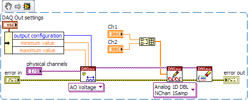
After contacting the support I was provided with the names of the more simple examples for analog i/o:
Analog output-Gen power Update.vi
Analog Input-Acq & chart voltage-Int Clk.vi
They are found in the getting started screen of
Click 'Find examples' near the lower right corner
Filter the results to material by clicking on the menu drop down for the material in the lower left corner and selecting USB-6343 (only connected equipment will be displayed)
Don't forget to check the box "limit results to material" below.
In the center pane, double-click 'Material Input and Output'
Double-click DAQmx
Path for the analog input - double-click Acq & chart analog measures - double click on tension - tension-Int Clk.vi
Double click on analog generation - double click on Power - Gen Update.vi of analog channel output voltage
The examples are for the single data point. Samples and exit multiples are produced by putting the writing or reading VI inside a loop. The beginning and the clear functions should be out of the loop.
Additional information, I need technical support was how material-filter results and identification of more simple examples which were not obvious from the examples of names.
Tags: NI Software
Similar Questions
-
Incorrect value for analog output USB-6008. Cannot not out more than 3V
I use USB-6008 analog IO, but the analog output (AO0 or AO1) can go up to 3 - 3.5V. The output can follow accurately the value of 0 to 2, 5V, but then he start the values adjusted trolling and not can not spend you 3.5V exponentially.
The only strange thing the entire circuit is that I connected all patterns (analog source and I/O 5V) between them, but I don't see what affect the output.
Kind regards
ISSOKO
Thanks for the quick reply Ana.
It is not the Council NOR, nor the Council of motorization. Apparently, the interface for motor control (motor spirit C: solutions - cubed.com), load the analog output. A tension following actually isolated op amp output USB-6008 and solved the problem.
Best regards, ISSOKO
-
Hello
I just started using an NI USB-6008 box. At this point, I don't need to fill all the specific tasks other than learning to use the device. I used a fair bit of LabVIEW but never with this kind of material, and I would like to help to understand it please.
In particular, I have attached a VI in which I try to get an analog signal through the USB-6008 and read again (also with the USB-6008 - I wired the pins together). However, I do not understand what is happening when I run this VI. I expect the output a sine signal of 10 Hz for 1 second, 0.1 seconds record and see 1 full cycle of the sine wave. In practice, I read about 10 cycles and constant tension then. Presummably, this means that either the reading continues for more than 0.1 second, otherwise the output signal is more than 10 Hz.
I also tried to use the related calendar DAQmx screws with the output pin to try to adjust the output rate (samples/s) but everything that I've tried return errors. I also tried to open some examples NOR, but these errors returned as well and I still just try things on mine.
Did I miss something obvious here, but any help would be appreciated!
Edit: I had to update this post & attached VI I had made mistakes. The default values on the front panel show what I see after the execution of the VI.
Orbital Hi,
As far as I know, you will need to use the DAQmx Read and VIs write in loops and functions of synchronization to determine data rates you want.
I also did a quick search and found a white paper which you may find useful: http://www.ni.com/white-paper/9541/en/
Kind regards
-
Arbitrary analog output USB-6281
Hello, I am very new to LabView and national instruments. I'm trying out a sinusoidal signal with noise with my usb-6281. I can't find how to do this in labview 8.2. I see how a normal sine wave of the express signal and the measuremtn Explorer & automation of output, but I would like to do a program in labview to run it. and not only a sine wave but a noise. Can someone point me in the right direction for this? is it still possible with the 6281? I should mention as probably as a sinusoid is not really necessary, I am controlling a variable voltage attenuator and want to change mitigation maybe 5 times per second, so the speed is not essential. I could even run it through a script of voltage levels. but I don't know how do either. Thanks in advance for your help.
Hi F11Raven,
The DAQ Assistant is packaged with DAQmx, which is the driver needed to interact with your USB-6251. You can download the latest version of DAQmx here. After installing, you should be able to use the DAQ Assistant in LabVIEW.
-
Sampling frequency of adjustment for the analog output of sine
Hello
I tried to do something very simple: using an analog output card PCI 6221 to produce a frequency 50 Hz sine curve. For this I used a Vi to create a curve sinus and different screws DAQmx. But I have trouble understanding the principle of virtual channel and I think I do an error of adjustment of the sampling frequency and number of samples: once for the vi, second time sine "DAQmx - synchronization. Can I use the same values for both of these screws?
On my oscilloscope, with frequency = 50 Hz and the sampling frequency = 1 kHz, I get a null signal. Then according to two values, I'm differently evaluated signals. For example, with f = 1 Hz and sr = 10 kHz, a frequency 0.7 Hz sinus.
Make sure that the start for the analog input task occurs after the analog output. By plugging in the wrong thread to an analogue output start task first, and then to the start task, you guarantee that the AI cannot start until after the startup of the AO.
-
Output analog, the USB-6009 case - can I use DAQmxWriteAnalogScalarF64?
I just got a NI USB-6009 and I try to use the outputs analog simple.
I'm running on a Mac, so I'll try to use the API OR-DAQmx Base 3.2 C (downloaded from here: http://joule.ni.com/nidu/cds/view/p/id/1078/lang/en). This is the most recent version of NOR-DAQmxBase, I could find.
I try to do continuous analog output on the 6009, which does not have a built-in clock. I was hoping to do the sync software and just new output values when I want to.
I can't get an output of database to work. Other messages and the example of Windows files, (e.g., National Instruments/NOR-DAQmx Base/examples/ao/MultVoltUpates-SWTimed.c) it seems that the best thing to do would be to use the DAQmxWriteAnalogScalarF64 function.
However, this is not in the Mac version of the C API of NIDAQmxBase. There is actually an entry for this in the NIDAQmxBase.h file, but it is commented out. Anyone know why? Is it possible to use this function for the analog output on request on Mac?
Thank you.
Clement
I have NEITHER-DAQmx Base installed 3.2 on a 10.4.11 system. One of the examples files 'genVoltage.c' calls DAQmxBaseWriteAnalogF64. I was able to compile and run this example with a USB-6009.
The DAQmxBaseWriteAnalogF64 function would work for you?
My guess is that, since you can write a scalar value with DAQmxBaseWriteAnalogF64, DAQmxBaseWriteAnalogScalarF64 becomes superfluous. The example provided with the installation shows how to write a unique value (i.e. scalar.). I pasted the code of OR below.
int main (int argc, char * argv [])
{
Task settings
Int32 error = 0;
TaskHandle taskHandle = 0;
char errBuff [2048] = {'\0'};
Channel settings
Char [] = "Dev1/ao0" chan
float64 min = 0.0;
float64 max = 5.0;
Sync settings
uInt64 samplesPerChan = 1;
Writing data parameters
float64 data = 3.25;
pointsWritten of Int32;
float64 timeout = 10.0;
DAQmxErrChk (DAQmxBaseCreateTask("",&taskHandle));
DAQmxErrChk (DAQmxBaseCreateAOVoltageChan(taskHandle,chan,"",min,max,DAQmx_Val_Volts,));
DAQmxErrChk (DAQmxBaseStartTask (taskHandle));
DAQmxErrChk (DAQmxBaseWriteAnalogF64(taskHandle,samplesPerChan,0,timeout,DAQmx_Val_GroupByChannel,&data,&pointsWritten,));
Error:
If (DAQmxFailed (error))
DAQmxBaseGetExtendedErrorInfo (errBuff, 2048);
If (taskHandle! = 0) {}
DAQmxBaseStopTask (taskHandle);
DAQmxBaseClearTask (taskHandle);
}
If (DAQmxFailed (error))
printf ("error in DAQmxBase: %s\n",errBuff); ")
return 0;
}
Hope this helps!
-
Strange analog output of USB-6211
I just got USB-6211 to replace USB-6001 to set the clock to external sampling on analog output for LED lighting control. The part of external clock example works fine, but the analog output voltage is strange. To do self-monitoring, I connected control pin LED to AO0 & AI0 of surveillance in the NI MAX test panel and LED control on the ground at AO - GND & GND HAVE since I have both USB-6001 and USB-6211, I conducted tests on two of them with the same setting of wire. When I generate sine wave - 5V to 5V to AO0 (from NI MAX test panel), USB-6001 can monitor the same signal AI0, but watch USB-6211 - 3, 4V to 3.4V voltage truncated. I did the test separately (wiring one device at a time), so there is no interference between the two devices. USB-6211 past self-calibration and self-monitoring. Also, I did reset devices. I don't know why they would behave differently with the same configuration, and I hope that someone could help with this question. Thank you.
Hi skuo1008,
The USB-6001 can support + / 5 output current my from terminals to analog output, while the USB-6211 box can provide only +/-2 my current output. It is likely that the load impedance is too low, causing the 6211 to hit its current compliance and thus cut the tension. If you try to exchange your load with a resistance of at least 5 v/.002A = 2500 Ohms, you should be able to see the full +/-5V sine wave. I suspect that your DUT has a words 3.4V/.002A = 1700 Ohms impedance. You could use a device with higher output current or use a more current source buffer circuit. If you do not need a bipolar output, you might also consider using digital lines to control the LEDs.
Kind regards
-
I inherited a data USB-6343 acquisition unit and tests a few pieces I designed. The latest version of the chip has 3.3V / s and it appears that the 6343 only supports digital i/o to 5V. Is there a quick way to convert the output data acquisition in 3.3V 5V? Thank you.
Hello
I thought it might be useful to display some of these to the top on the same topic:
I understand you are trying to run the code example "Static digital output with adjustable logic level. When you set the level to 3.3V logic you see an error message.
Here is an article on knowledge (KB) which explains what this message means. In this KB is now talking of another property, but the concept is still the same.
http://digital.NI.com/public.nsf/allkb/05A563FE3AA7B3C286256FF90077C303?OpenDocumentI also did a little more research and found this useful reference which caught shows supported properties for the device, and you can see that this property is not supported.
http://zone.NI.com/reference/en-XX/help/370471Y-01/cdaqmxsupp/USB-6343/In conclusion, you are limited to the 5v output only if you need to obtain 3v to drive your relay maybe I could suggest that you use a converter logic circuit that converts your 5v with 3.3V.
I hope this information helps.
Let me know how you go.
Kind regards
Kevin Ross
National Instruments
Engineering applications
www.NI.com/support -
NEITHER USB-6343 analog and digital grounds
In the manual for the NI USB-6343, it is said that the mass input/output, analog and digital terrestrial are related, but by a small sign. For my application, I am attaching all 3 these grounds to exit the box (I'm tie all areas with physical threads). It is perhaps a silly question, but it's OK to do, correct?
This should be OK unless there are large currents flowing on ground conductors. If you have important currents in the ground, you have other problems that must be resolved before you connect the DAQ hardware.
Lynn
-
synchronize the outputs digital AND digital NI USB 6343 entry
Hello
I use NI USB 6343 to fly 1 TTL devices. This device can also produce a TTL signal to indicate if the door is opened/closed.
I use digital Bool 1 line 1 Point. I was able to reverse the opening/closing of the door on time. But I would like to synchronize the DI and DO it right.
I tried to throw in the clock aboard, but he failed.
Is it possible to synchronize the DI and DOI onbaord/hardware clock?
Any idea will be great!
Thank you!!
Hello
Synchronization of your tasks of DI and shouldn't be possible with your device. You'll need them timeless has a clock that is usable by both. This information is available in the X series user manual
http://www.NI.com/PDF/manuals/370784f.PDF
PG 6-9 and 6-13You can also find information and examples of synchronization of the various tasks in the article below.
http://www.NI.com/product-documentation/4322/en/Good luck
Eric
-
Reconciliation of analog output NI USB-6210
Using Labview, I am currently using an NI USB-6210 to produce a signal that a BOP of Kepco 50-2 M feeding programs. Unfortunately, this device NOR produced no analog voltage. Is it possible that I can use the digital output or against the unit OR to do something that approximates an analog output? I need a way to get the power output voltage has the supply to increase gradually in a predefined way. I only work with a couple of volts because of sensitive equipment, so accuracy is important.
I don't have access to the program at the moment so I don't know what version of Labview that I use, but I'll be able to check in a few hours.
Its probably not worth to use this device in a method not scheduled. Cheeper with analog outputs are available.
And don't forget the 4886 BIT card that can be purchased and hooked to your diet, there are even for using RS232 or GPIB device drivers to control the supply to
-
It is current on the analog module USB NI 9263 output voltage limit (+/-10 v)?
It is current on the analog module USB NI 9263 output voltage limit (+/-10 v)? I try to run a current controlled resistance, but cannot get the required current. The servovalved has a parallel internal resistance of 80 ohms and requires 20 my full operation. Ohm's law: (.02 A) * ((80*80) /(80+80) ohms = 4.5 v) Yet, the required voltage, do not move the servo. Outside the material error (continue this by other means), what could be the problem?
Have you checked the Manual?
Page 12 1 says my.
For servo, you really need some kind of amplifier. See if the manufacturer provides the electronic driver for it.
-
Several simultaneous analog output channels
I use DAQmx-NOR-USB.
I want to simultaneously generate two analog output signals, i.e. change the two outputs at the same time.
Simple example:
What is happening is that instead of two outputs simultaneous modification, there is 1mS delay:
I want to generate premium output, using two channels, but the delayed response is not acceptable.
Any suggestions?
Hi Seth B,.
Yes, it works!
A note: to make visible this property, I had to turn on "display all the attributes" in the menu "Select filter" (right click on the node property).
Thank you.
-
Input/output USB 6008 test failure
OK I am posting this for the third time, but whenever I go back to the home page of the forum, I'm not able to find my post. If by chance I created duplicates than apologies.
IAM in train to test the USB-6008 case I just got and decided to hang the analog of the analog inputs and see using labview VI.the wiring was done as:
http://i284.Photobucket.com/albums/ll5/bigdawg6/USB%206008%20wiring_zpss2b7hql9.jpg
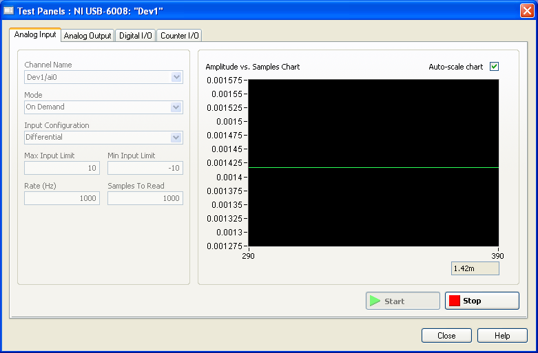
the problem is that the labview VI did nothing, so I go to NI Max and try to see in test panels. But I get 1.4V constantly my same analog input value when I'm changing my analog value:
http://i284.Photobucket.com/albums/ll5/bigdawg6/AIO%20screenshot_zps9beiimbj.PNG
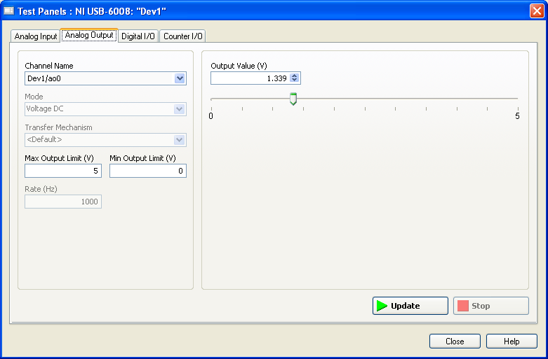
the analog output works very well since I plugged it to my multimeter and I can see the tension that I see on this Panel of test:
http://i284.Photobucket.com/albums/ll5/bigdawg6/AO0%20screenshot_zpsqpei37bw.PNG
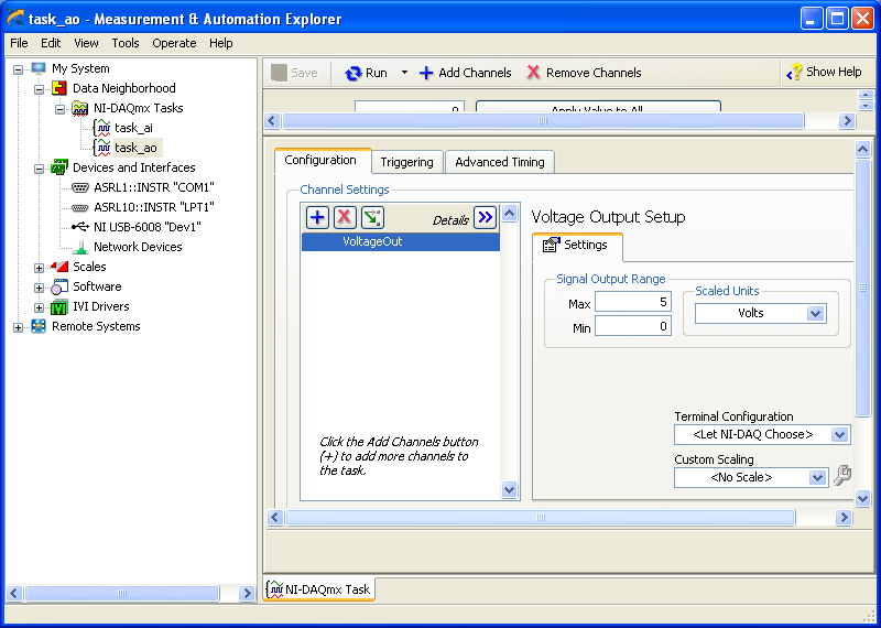
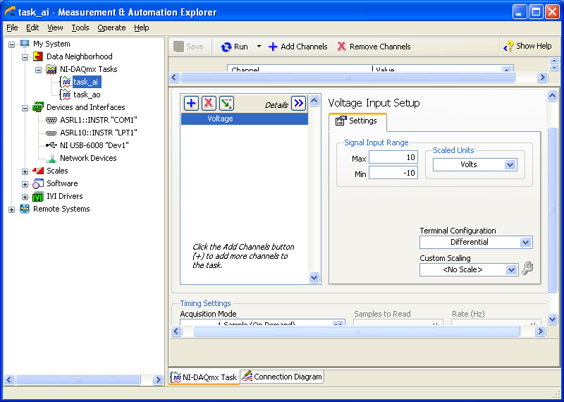
I created an entry/exit of the tasks; screenshots of them are:
http://i284.Photobucket.com/albums/ll5/bigdawg6/task_ao_zpsykmvczew.PNG
http://i284.Photobucket.com/albums/ll5/bigdawg6/task_ai_zpsix5se9yg.PNG
I am quite frustrated with all this since I'm unable to access my actaul draft. I know that 1.4 V value is from the device itself; as in the manual it says 'internal resistance divider can cause the Terminal to float at about 1.4 V when the analog input terminal is configured as a CSR', but the funny thing is that I use it in differential mode so I don't know what to do and any help is appreciated.
BTW, I did a google search and there are other tutorials onlune who seem to do exactly what I do and they seem to work very well; so I don't know what else to do.
Please don't host images on some odd third-party site. Attach them to your message.
I don't understand what you've done. The 6009 can produce only a signal of CSR in order to set up the differential input makes no sense. If you want to measure something different, try a simple battery.
-
Redeclenchables/continuous to a custom waveform analog output?
Hello
I try regular output an analog signal using the box USB-6211 and Labview2009. I looked at various examples of waveform, including the retriggerableAO.vi example, but I can't seem to understand how to send a 'waveform' custom stamp (terminology is perhaps the question). In all the examples (including waveformbuffer), I ran across the single waveform, the options are sine, square, etc. Previously, I posted on this forum looking for hardware suggestions (link here) and explained what I try to do and got the big help. To sum up, I would like to read a 'waveform' from a text file, send it to the usb-6211 buffer and then continue to an analog channel. At the same time, I'll use the beginning of the analog task to trigger a digital signal once per cycle as well.
I got in what concerns the establishment of the waveform, but am stuck to figure out how to get into the buffer and setting the frequency, etc.
Thank you
Gabe
Hi Gabe,
Dennis is correct that it will take some room to modify the existing screws to fit your need. As he says, the Con Gen tension Wfm - Int Regeneration.vi Clk - no example provided with LabVIEW. In the example, it can be shown that there is a custom VI used to explain the problems that arise when a waveform of a given frequency to a frequency of sampling and outputs analog specified.
With all that said, it seems you want to read from an existing waveform file that you created and this waveform to an AO output channel. There are a few things that will be needed to know before proceeding:
-What is the waveform as you try to output (5000 samples, 10 k, 100 k, etc.)?
-What pieces of the size of the wave you want output (100 samples at a time, etc.)?
-you want to again and again, or simply run through once the waveform looping?
Assuming that you already have the waveform and will only step by step, here's what I would like:
-break the large waveform into smaller pieces of waveform of standard size
-import the waveforms in LabVIEW and create an array of waveforms
-bring the waveform in the example Dennis mentioned previously with automatic indexing enabled on the tunnel
-Remove the generator of wave functions existing the while loop
-wire your indexed table of waveform for the data of the VI DAQmx of analog output terminal
It is possible that you will have to play with the settings of your waveform and timing of your VI, but this should be a good starting point. Please let me know if something is not clear or if I have misunderstood your original message. Have a beautiful reast of the day.
Best,
Maybe you are looking for
-
A PowerMac G4 software restore disks (June 2003 MDD)
No one knows what the numbers for the installation discs that would come with a June 2003 MDD? I see the latest Apple G4 never released, configured by default with a single processor 1.25 and could boot OS 9 natively. I did a lot of digging on this s
-
Pavilion 15 laptop: a matter of microsoft
can someone tell me what Microsoft Visual C ++ must be installed to date. Product number: K7R25EA #ABU HP Pavilion 15 laptop. because I had errors in the C++ severel is this week when trying to reinstall non-functional programs (management of intel
-
TECRA M10 (models PTM40E/PTM42E) for Windows 7 upgrade
HelloWe have two former TECRA M10 (models PTM40E and PTM42E) and you want to update the PC now for Windows7. After the installation of a new (larger) HARD drive, we ran the recovery DVDs. After that recovery completed successfully, we have installed
-
I'm looking for help to decide whether to upgrade to Labview 2009. My Department provides an upgrade to our current 8.2 in the coming months. There is the legitimate concern that the new version of a program is not always stable, so we are leaning
-
Driver Epson Stylus NX 127 for
I am trying to install a printer Epson Stylus NX 127, I bought earlier this year, when I bought and installed everything was ok without difficulty, but after some use, but I unplugged the printer and has continued to use my previous printer who was a