Several simultaneous analog output channels
I use DAQmx-NOR-USB.
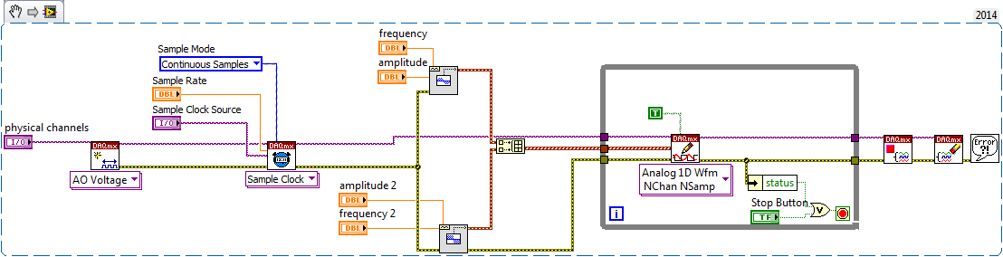
I want to simultaneously generate two analog output signals, i.e. change the two outputs at the same time.
Simple example:
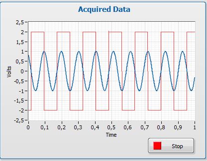
What is happening is that instead of two outputs simultaneous modification, there is 1mS delay:
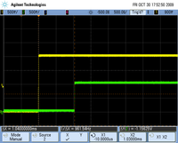
I want to generate premium output, using two channels, but the delayed response is not acceptable.
Any suggestions?
Hi Seth B,.
Yes, it works!
A note: to make visible this property, I had to turn on "display all the attributes" in the menu "Select filter" (right click on the node property).
Thank you.
Tags: NI Hardware
Similar Questions
-
Acquisition of multiple simultaneous analog output data
Hello, I'm doing a program when a user telnet to my computer and labview will recevie provided cn and analyze. then, he deciphers the emssage find what analog output it trying to change and then change it. I all the work, but I get error 50103 who say I can't have 2 screws DAQ assistant express running simultaneously. I want to have 2 different signals on A0 and A1 on my surfboard USB-6281. Is this possible? Thanks in advance. BTW im using labview 8.2
The vi in LV2009 is attached. I did the mods I had described. It should be a beginning. Modify if needed.
-
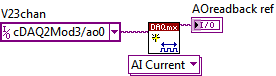
Read analog output channel value internally
According to this you can read the values of analog output of return without having to physically connect the wires.
By using the technique described in the example given (DAQmx_Read_Output_Internal_Channels.vi) I'm reading a current area of OCCUPANCY on my compactDAQ cDAQ-9174 with a module of analog output current OR-9265.
The output channel is created in MAX and my vi can write values to him without problems
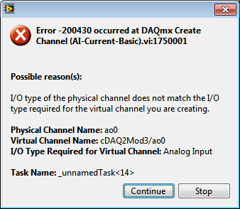
But when I try to create an analog input channel to read the output, an error occurs.
What I am doing wrong?
This is not supported by my hardware?
Or is the example given in the above incorrect link?
The example is 10 years old. Maybe, it does not work in LV2013.
Hi Jocker,
The link was not attached to your message, but I guess that's it: http://digital.ni.com/public.nsf/allkb/CB86B3B174763C3E86256FFD007A2511 as there the example of vi you mention.
The error you are getting is due to the use of the channel for analog output and trying to configure the task as a task of entry. You must use _aoX_vs_aognd as the channel of the task rather than on the output channel. This compares to the ground for the analog output values.
The NI 9265 is not on the list of the C Series modules that have internal channels:
So I guess that the module is not able to compare its output to ground. He would appear in the dropdown of the channel names if available.
Pete
Applications Engineer OR
-
Sending of different waveforms on two separate analog output channels
Hello NOR community,
I am trying to send a note to say 100 Hz signal on one of the channels on my computer USB 3101 FS Measuremnt and a sinusoid 300 Hz on another channel. I've seen a lot of soultions to this problem, but I do something wrong in my attempt to imitate. As a result of the use of a product of MC, I use the library instead of DAQmx Ulx, but the Vi is virtually interchangeable features wise. In any case, I managed to send two signals (see annex VI), but they are still the same in terms of amplitude and frequency. In other words, I get the same signal on both channels as opposed to the two different signals of different frequencies.
Thanks for your suggestions,
Leo
Hi Lemmeneger,
I have reproduced what you're trying to do, but using DAQmx since I did no material of MC. And had no problem sending two different analog ouptuts.
Could you try to wire the errors? and let me know if something doesn't appear! I do not see a problem in what you are trying to run
Kind regards
Caroline
-
Recommendations for hardware OR with a minimum 6-channel analog output
Hello world.
Currently I have the NOR-device, USB-6009. However, it offers only up to 2 analog output channels. I'll need to have at least 6 channels of analog output. Therefore, can anyone recommend me any device OR that matches my needs (preference is the USB series)?
Kind regards
Jonathan
Did you go to the page data acquisition . You can use the different selection tools to narrow down your choices. Given that you have provided only a single parameter (number of channels), it is difficult to recommend anything. Determine what else you need (sample rate, voltage range, etc.) and you can call your sales engineer OR local and get all the help you need.
-
Hello
My question is about the analog output (0 - 10V) of the myDAQ unit.
On the card, you can read:
"Overdrive Protection +-16 V forever."
Lets imagine the worst case: 0 V output DQA, but outside a battery or anything else is connected with 15 V to the analog output.
Fact an "unlimited" current in data acquisition or protection 'Overdrive' works here and the material is safe to destroy?
The background: I want to OD are protected from transient voltages and toilet on a simple zener diodes clip or a tvs diode...
Thank you all, Markus
Markus,
To use a zener diode as protection, you must also have an impedance of current limiting in series with the source against which you are protecting. The manual for the device of maDAQ indicates that the lines of the AO are pushed by OPA1642 op amps. TI the MSDS for this unit shows the current limiting internal ~ 36 my short circuit with Earth and a thermal shutdown circuit that tries to protect against the terms of overpwer.
However, under your 15 V battery, 11 V zener and 0 V programmed DAQ exit, the situation may be different. The current from the battery through the zener will be limited by the impedance of cables or any type of resistance on the line. This has no direct effect on the myDAQ device, but it will probably destroy the zener unless resistance limits the current to a lower maximum current nominal zener. As long as the voltage at the output of the myDAQ is lower than the internal supply voltage (+/-15 V), on the OPA1642 current limitation should apply. With 11V applied to the output and the value set to zero the device would probably be to try to sink the maximum current for-15 V power supply. Which translates to a dissipation of power of more than 900 mW, which exceeds the rated capacity of the op amp. Themal protection should, in principle, reduce the current to a level that does not exceed the thermal limit under development.
This test can be a costly process. The unit may be destroyed. Given that the maximum current specified for an analog output channel is 2 my and the maximum voltage is 10 V, I would consider a series resistance of perhaps 1000 ohms and clamping schottky diodes at the + 15 V and - 15 V power supply. This will limit the current to 10-20 my in all conditions you have mentioned and would also provide protection to the case where the battery is connected the myDAQ device is turned off. He alsoe does not care about the polarity of the external source. It will drop the output voltage according to the load impedance. If this should be used in a student lab, the calcualtion of this decline is something they should be doing anyway, and would be a small price to pay for protection.
Lynn
-
acquire the voltage output of a channel of analog output current
I'm controlling a HV configuration rather sensitive analog output voltages. Is there an easy way to read the voltage level which is currently awarded by an analog output?
Hello
If you set your subVIs different voltages, you can be sure that the voltage you set in these screws are similar to tensions, you have to your output PIN. For example, you could write the value you give to the output in a variable and read this variable in you main VI.
Kind regards
Peter
-
How to write constantly to analog output and read from analog inputs
Hi all -
I had a question about writing continuously to analog output reading simultaneously an analog input.
It's my first time to post a message to the community, so please let me know if I made mistakes.
I use Labview 2011 with a NEITHER-DAQ USB 6215.
I'm looking to generate a waveform and write it continuously in an analog output. It is then connected to an entry on the acquisition of data, where I am trying to sample the analog signal. (I realize, there is a system of trivial, but I'm hoping to build on it once I have run).
The task of reading from the analog input works fine, as I tested it in several other cases. I have a problem writing to the analog output.
For this task, I tried to follow the "Gen Cont Wfm Clck Int' VI to generate the wave form and start the task. I then try to write to the output of the analog timed loop. However, it does not seem to transmit a signal and doesn't give me any errors.
I have attached the VI but also a screenshot.
Please let me know if anyone has any ideas. I would really appreciate the help!
Thank you
Peter Borgstrom
We will review your tasks one at a time. First of all, the task of generation/Analog output Waveform. Generate you a waveform (I'm unsure of your VI if it is a fixed waveform or not) and send it to a defined output function to produce a waveform continuously, using N-channel and samples of N (where you set not these previously). You should not put this inside has timed loop, as the DAQ hardware has its own clock - if you simply put it in a while loop (with a stop to break out of the loop), the loop will call the function for the first points of N, wait until all N have been taken out, then call it again to another N points (up to what you press Stop).
Now, suppose that you have the output connected to a load voltage (say a decent resistance). You can wire the input terminals of your A/D converter through the same load and set up a similar analog input loop, running in parallel (i.e. in its own independent of the OD loop, while loop). You pourriez start together (with, say, a merged error since the initialization code line loops HAVE and AO become lines of error in "loops of sampling" described above), but you might want to delay loop (a little) the AI so that the OD has a chance to set the voltage before the bed.
I hope this helps.
BS
-
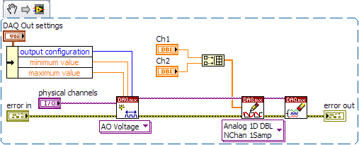
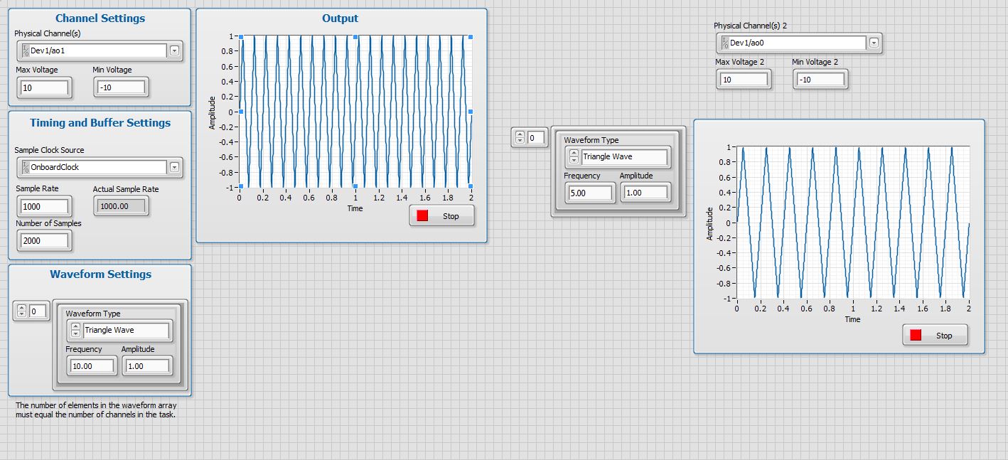
How to control the two analog outputs at a time
I'm new to LabVIEW and have some problems in DAQmx with control outputs analog multiple.
I want to set up a platform using BNC-2110 and PCIe6363 to control two rotating mirrors. The problem that I can only give an output (AO0 or AO1) at a time and I really have no idea how revise my LabVIEW diagram to control two outputs at the same time I met. I tried to change the outputs and it keeps a mirror turning instead of the old. Could someone help me with my problem and I would really appreciate. This is my blocked diagram and front.
Hi zrmaker,
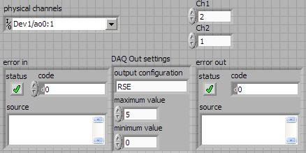
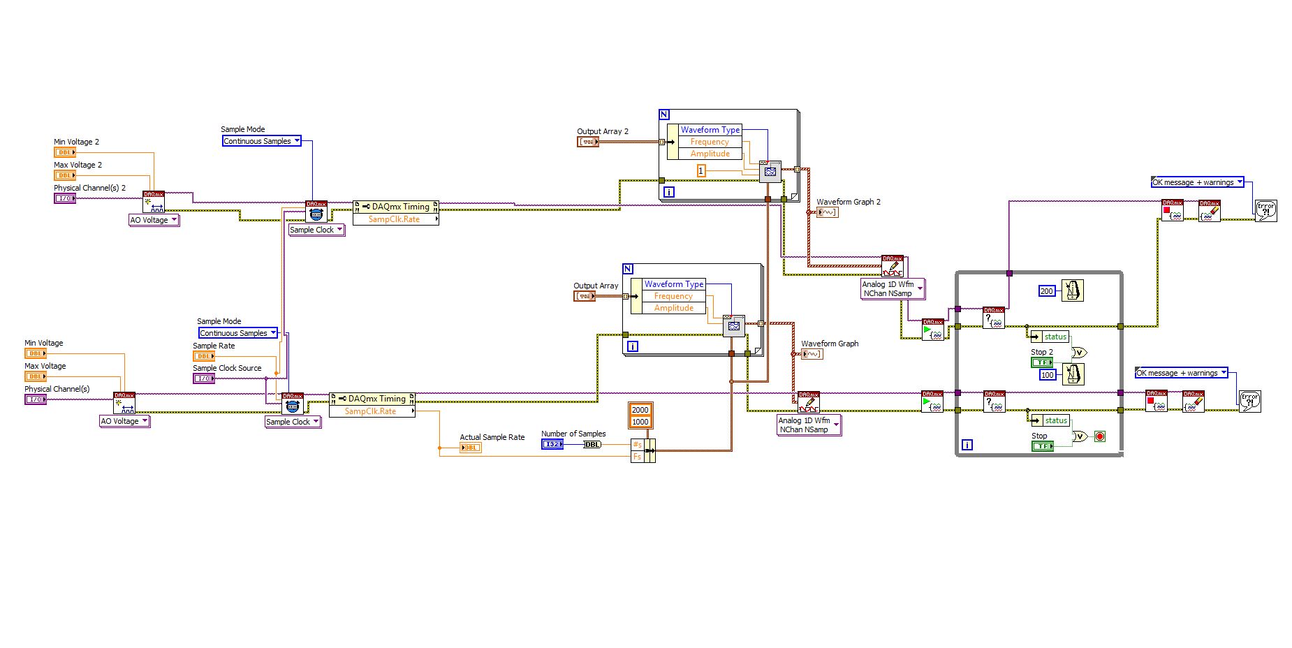
As mentioned by RavensFan, you should not create 2 analog outputs different tasks if you use AO0 AO1. To your façade > physical control or the channels > select the drop-down list of the control channel physical (s) > Browse > hold down the CTRL + select the AO0 and AO1 > Select OK. Once this is done, you will see that your control or the physical channels has the following input values: "Dev1 / ao0:1" which means that you will access to AO0 AO1.
In regards to writing DAQmx, simply select Analog > multiple channels > samples multiple > 1 waveform (you should get the following: 1 d Analog Waveform NChan NSamp). Once done, you can just use table build to combine 2 different waveforms and plug in this table to DAQmx writing output. The first index will be the output for AO0 value and the other will be for AO1.
You can check this link on how to read or write from several channels: http://digital.ni.com/public.nsf/allkb/0C1ADEF06A54AB2D862575040066FD51
Additional reference:
http://www.NI.com/white-paper/2835/en/Hope that helps.
Warm greetings,
Lennard.C
-
Analog output of signal generation custom
Hello
I have a VI that generates a signal from the values in an excel worksheet. I'm trying this waveform through an acquisition of output data. I use a box NI USB-6211.
I copied the exit code for the acquisition of data from other VI that generates a sinusoidal signal coming from an excel worksheet. This program works very well. (attached for reference - Analog Output VI + sinusoidal waveform)
I have two problems at the moment. First of all, I get error-200560 about waiting until the function, attached.
Second output amounts only to about 5.5 v instead of 9V specified in the data.
My VI generate several types of waveform according to selected tests, but I'm trying to get an output DAQ working with the first test, named "disconnection of the battery" work first before implementing it in the other tests so please ignore others for now. To run this battery select VI disconnect under tests select then direct to the attached excel (BD values under 10V) file.
I hope that I myself have pretty much explained, otherwise please ask for more! I'm new to LabVIEW so your help would be very appreciated.
Thank you very much
Parker
aeParker wrote:
I've made a few improvements to the VI but I always feel the DAQ 5 Cap output, 5V.
Dear Parker,
I guess that this statement is based on the values in the chart show, AO 0. However, this is not (necessarily) the voltage produced by AO 0, but rather the tension being sampled by AI0. If you look at the DAQmx create channel for the AI voltage channel, you will see that you have left entries Maximum and Minimum Value unwired, which means that they take their values default to + 5v and - 5v. This may explain the behavior of cutting that you observe. Try the + 10 and -10 wiring and see if that solves this problem.
Bob Schor
-
Analog output PCI-6251-DAQ-200016 memory overflow error
NI PCI - 6251 DAQmx, AIMD-752 motherboard, dual core processor, a lot of speed and the ram running WinXP Pro & LabWindows/CVI
get DAQ-200016 memory overflow error when I try to generate a signal of analog output with a rate higher than about 32 000 samples/second (?)
going on what? I have never seen it before. Is this a problem with the motherboard? "It's the same product on the CVI code example" \Cont Gen Volt Wfm - Int Clk\ContGen - IntClk.cws.
If someone has had this problem, and is there a solution?
Thank you
PS: full text of the message reads:
Measurements: On-board memory precision passing. Due to the limitations of system and/or the bandwidth of the bus, the driver could not write data to the device fast enough to track the rate of output of the device. Reduce your sampling rate, change the method of transfer of data (from interruptions on DMA), use a product with more on-board memory or reduce the number of programs that your computer runs simultaneously. Task name: _unnamedTask<1> Code of State:-200016
Well, I found my answer. For later use, Olivia NI Apps Engineering suggested I have change the mechanism of data transfer by this Knowledge Base document:
http://digital.NI.com/public.nsf/WebSearch/C326F7D33CA6DB0E86256DFE008043B7?OpenDocument
... so I inserted the line of code between the creation of the area of OCCUPANCY of the channels and set up the example of clock calendar.
DAQmxCreateAOVoltageChan( ...

DAQmxSetAODataXferMech(TaskHandle,chan,DAQmx_Val_Interrupts);

DAQmxCfgSampClkTiming(...
now, I am able to generate output to a 2.35 MS/sec... max sampling frequency not quite the 2.86MS / sec indicated in the specification 6251, but close enough that I'll stop complaining

-
To input analog shutdown when the analog output is completed and synchronization
Hello
I'm trying to get my LabVIEW program to send analog output to a computer and read acceleration using the cDAQ-9184. Chassis output that I use is the NI 9263 and the chassis of entry is the NI 9234. I generate a signal of white noise using LabVIEW Express signal generator.
The first problem I have is the synchronization. I had an old VI that has begun to measure the acceleration just about a second after the entry has been given to the machine. I used the LabVIEW tutorial on how to sync the analog input and output, only to discover that it does not work with two different hunts. Then I found another tutorial that shows how to synchronize different frames between them.
The second problem is the cessation of the LabVIEW program. What I want to do is to generate the signal and then simultaneously send and read the input and output analog, respectively. It is because I don't want a phase difference or any shorter signal for a direct comparison. But as soon as the signal is sent to the machine, I want the entry to stop analog playback and then then the LabVIEW program must stop. I want to be able to choose any length of signal to be generated and stop as soon as the entire duration of the signal has been sent to the machine.
I tried 'DAQmx stop', "DAQmx Timer" and 'DAQmx's task made?' and none of them have worked for me. It is also my first time on a forum posting, so I hope I gave enough information. I enclose my VI as well. The VI shows I read an entry for the analog input voltage, but I am only using this to try to get to the work programme.
I'd appreciate any help I could get.
Thanks in advance
Peter
Hi Peter,.
I have some recommendations for you that I think you will get closer to your solution. First of all, I assumed you meant that you had 1 chassis (cDAQ-9184) who had two modules in it (NOR-9263 and NOR-9234). My next steps are based on this assumption, so if it's wrong, please let me know.
For your first question about the synchronization, the code you provided is very close to what you need. You need to do, however, implement architecture master/slave for startup tasks DAQmx functions. To do this, you can add another frame to the flat sequence structure and put the master start task (input voltage) after the start slave (output voltage) task.
To manage your second question and that the program ends at the point where you, the first step is to get rid of all the logic that you use with the local variable of length of time. Rather than use this logic, just wire the node "task performed?" of "is task performed?" operate to stop the loop. This will cause your loop to stop as soon as the signal is sent to the machine.
I have some other recommendations for you that will increase the performance of your program:
(1) rather than writing on file inside the last loop, you can use the DAQmx Configure Logging (PDM) .vi. You will place this VI between DAQmx Timing.vi and DAQmx Start Task.vi to the task of the analog input voltage.
(2) after the last while loop, you want to stop the task and analog outputs as well with another DAQmx stop Task.vi.
(3) rather than using a local variable for the entrance of displacement and wiring it in the DAQmx Write.vi, you can wire directly from the output waveform of the wave to build function node.
That should help you get started in the synchronization of these tasks.
-Alex C.
Technical sales engineer
National Instruments
-
Simulate the analog output of arbitrary waveforms
Simulate it Arbitrary Waveform VI Express can be used to generate analog signals to the physical channels in analog output mode systems such as the NI 9263? I am trying to use the VI arbitrary signal generator to produce a signal used to excite the magnetic coils.
Why don't you just try and see what happens? As far as I know, it should work.
-
How can I check if the counter entry is synchronized with the analog output?
Hello
I'm working on an application for counting photons. I use two channels of analog output on a PCI-6713 card to send a frame model to a set of XY scan mirrors. I then a photon count unit that emits a TTL signal when the photons are detected as a result of this raster analysis. I then use a surfboard USB-6211 to count the edges on this TTL signal.
I have problems that seem due to synchronization problems. I use the sample AO on the PCI-6713 card clock like the door of my meter on the map USB-6211. I use a trigger to start digital to analog output and a trigger of arms for the entrance to counter early. Is there a way to check that the analog output and counter entry of start of operations at the same time and are are synchronized? I basically want to monitor and compare the ao real sample of the PCI-6713 card clock door signal used by the jury of the USB-6211. I was able to export the sample AO clock and watch it on my oscilloscope, but not the signal from the door of the USB-6211.
Thanks for your help,
Brian
Update... It turns out that there is no problem of synchronization between my meter input and the analogue output. There was a difference of impedance when I connected my unit of counting photons to my USB-6211. This caused an error variable count rate. After accouting for this shift, the problem disappeared.
-
read the output of a path of analog output current voltage
In DAQmx if you are unsure of the status of a digital output port, you can take a reading on this subject. When I try this on an analog output, I get an error. Is it possible to query the status of the output of an analog output? I realize that I could follow the State with a variable, but a direct reading would be really handy.
Hello, GIS.
There is no way to read the output in the AO modules without wiring physically the signal to a module to HAVE. You are able to use a variable to read the current value of the output, as you mentioned earlier.
Channels AO multifunction boards, however, can be read through tasks of entry by rounting in-house channel to read ao vs aoground.
Lisa
Maybe you are looking for
-
try to download a game and he keeps asking passwor and admimistrater name
I'm trying to downlad a frpm bigfish game but it keeps asking for password and the name of administater that I do not understand how to do this, I put my name in but I do not have a password
-
Try installing Adobe Acrobat updates.
When I try to download the updates, I get error 16299.103.516 operating system - 73172312.80004005.FFFFFFFF.00000000. Need help!
-
How can I install MASM in Windows XP 32 bit OS?
I want to program a microprocessor 8086 by masm or tasm. So can someone please guide me through the process of installing MASM X 86 and X 64 MASM on windows XP 32-bit I would also like to know the sources of books to learn Assembly language for progr
-
Do not connect ANALOG and digital grounds when the annotation to the front at the UB
I'm finding randomly more often when I annotate with impatience to UB analogous and digital patterns do not connect. In addition some power to the IC pin connections are unable to be connected in UB. Connect to the digital terrestrial analog ground
-
80070490 error when you install KB948465
Impossible to update windows since November 12 Windows Vista Service Pack 2 32-bit of the opp system Do not have my original DVD discs. I tried Mocrosoft difficulty, PC Maestro. Try the error end, but understand that it is not compatible with Vista