the time of acquisition of data - how to calculate the rate of analog output
I want to calculate an acceptable rate of analog output, one that is taken in charge by material (PCIe6353), without the rate being changed by the VI DAQmx Timing (sample clock). The final objective is to have a rate of analog output that is an integer multiple of the analog input for precise frequency, since the sinusoid AO's amplifiers, which have a ringtone when AO updates occur.
According to 27R8Q3YF of the knowledge base: how the actual scanning speed is determined when I specify the rate of scanning to My d..., the rate is revised as needed by calculating the rate of clock / asked for advice, divide the result rounded downwards and upwards in the clock of the Board and use the one that is closest to the requested speed.
If 'Embedded clock' is selected, which is the result "Council clock. DAQmx sample clock timebase Timing node - SampClk.Timebase.Rate says 100 ms/s. However, for a rate resulting from the update of 2.38095MS / s, the divisor of the time base timing node - "SampClk.TimebaseDiv" gives a value of 42. 42 x 2.38095 M = 99, 999, 990, where it should be 100 ms/s.
How to calculate an acceptable rate of analog output is supported by the hardware? I have other plates, in addition, a general method would be appreciated.
I haven't worked all the details yet but noticed a few things that may be relevant.
Req AI rate isn't a whole ditch 1E8. It is used to determine the rate of the AO.
There is no check to ensure that the rate of the AO is an integer division.
It seems that you have the right idea, but the implementation is not yet there.
Lynn
Tags: NI Software
Similar Questions
-
How do I synchronize pxi-6341 analog output to the analog in pxi-4304
I have an SMU-1082 chassis that contains a high-6341 and a PXI-4304 module. I went out a sinusoidal signal of pxi-6341. AO.0 channel for the pxi-4304. Channel ai.0. The pxi-4304 isn't receiving all signals up to about 75 MS later. How can I synchronize synchronization between the 2 modules together to stop this loss of data?
(Finally, I run a waveform digital off the 6341 and in a device while the 4304 captures analog response from the device. "So I'll need to have all sync'd up).
Thank you for your help,
Ron
After trying many "tricks" with various DAQmx screws, I finally found the solution. I simply had to stagger the 'task to start DAQmx' between the entry and exit, as shown in the attached photo.
Hope this helps someone.
-
How to calculate heart rate in a simple way using visa series
I am new to Labview, it's my mini project title "PC based ECG monitoring. I have this mini album, part hardware circuit ECG and DAQ (MPLAB) who will be using Labview for graphical user interface. My problem is, I made the graph for the ecg monitoring, and I need to calculate the heart rate and to detect bradycardia and tachycardia. for bradycardia is more or equal to 100bpm and tachycardia is less than 60 BPM. for the diasease 2, when it is either a bradycardia or tachycardia, the alarm lights. I also have a problem to make the detection of peaks and mark all the peak maximum and minimum and put the location of the peak. Thank you. Here I set my vi.
This is the complete...
Thank you very much.. -
To input analog shutdown when the analog output is completed and synchronization
Hello
I'm trying to get my LabVIEW program to send analog output to a computer and read acceleration using the cDAQ-9184. Chassis output that I use is the NI 9263 and the chassis of entry is the NI 9234. I generate a signal of white noise using LabVIEW Express signal generator.
The first problem I have is the synchronization. I had an old VI that has begun to measure the acceleration just about a second after the entry has been given to the machine. I used the LabVIEW tutorial on how to sync the analog input and output, only to discover that it does not work with two different hunts. Then I found another tutorial that shows how to synchronize different frames between them.
The second problem is the cessation of the LabVIEW program. What I want to do is to generate the signal and then simultaneously send and read the input and output analog, respectively. It is because I don't want a phase difference or any shorter signal for a direct comparison. But as soon as the signal is sent to the machine, I want the entry to stop analog playback and then then the LabVIEW program must stop. I want to be able to choose any length of signal to be generated and stop as soon as the entire duration of the signal has been sent to the machine.
I tried 'DAQmx stop', "DAQmx Timer" and 'DAQmx's task made?' and none of them have worked for me. It is also my first time on a forum posting, so I hope I gave enough information. I enclose my VI as well. The VI shows I read an entry for the analog input voltage, but I am only using this to try to get to the work programme.
I'd appreciate any help I could get.
Thanks in advance
Peter
Hi Peter,.
I have some recommendations for you that I think you will get closer to your solution. First of all, I assumed you meant that you had 1 chassis (cDAQ-9184) who had two modules in it (NOR-9263 and NOR-9234). My next steps are based on this assumption, so if it's wrong, please let me know.
For your first question about the synchronization, the code you provided is very close to what you need. You need to do, however, implement architecture master/slave for startup tasks DAQmx functions. To do this, you can add another frame to the flat sequence structure and put the master start task (input voltage) after the start slave (output voltage) task.
To manage your second question and that the program ends at the point where you, the first step is to get rid of all the logic that you use with the local variable of length of time. Rather than use this logic, just wire the node "task performed?" of "is task performed?" operate to stop the loop. This will cause your loop to stop as soon as the signal is sent to the machine.
I have some other recommendations for you that will increase the performance of your program:
(1) rather than writing on file inside the last loop, you can use the DAQmx Configure Logging (PDM) .vi. You will place this VI between DAQmx Timing.vi and DAQmx Start Task.vi to the task of the analog input voltage.
(2) after the last while loop, you want to stop the task and analog outputs as well with another DAQmx stop Task.vi.
(3) rather than using a local variable for the entrance of displacement and wiring it in the DAQmx Write.vi, you can wire directly from the output waveform of the wave to build function node.
That should help you get started in the synchronization of these tasks.
-Alex C.
Technical sales engineer
National Instruments
-
analog output digital start trigger the api c
Hi, I'm trying to start analogue output based on a digital trigger (either PFIO or a PXI line) I can make this easy in LabVIEW. However with the C API (through the Python wrappers), the problem is when I call DAQmxBaseWriteAnalogF64, writing will always be timeout that the acquisition was not triggered. However, I can't call it after the trigger occurs, because obviously, it will be too late.
I can't find any examples of C API where the analog output is triggered a digital triggering. I can find for the analog input, but is fundamentally different that you can CONV read anytime after the trigger occurs.
Python code as follows (functions are equivalent ot C API, even if you have no need of ot pass the task handle such that it maintained as part of the Task object)
# create analog output task
analog_output = Task()
analog_output.CreateAOVoltageChan("Dev1/ao0","",-10.0,10.0, DAQmx_Val_Volts, None)
analog_output.CfgSampClkTiming("",outputRate, DAQmx_Val_Rising, DAQmx_Val_FiniteSamps, numSamples)
analog_output.CfgDigEdgeStartTrig("/Dev1/PFI0", DAQmx_Val_Rising)
analog_output.StartTask()
analog_output.WriteAnalogF64(numSampsPerChan=numSamples, autoStart=False,timeout=1.0, dataLayout=DAQmx_Val_GroupByChannel, writeArray=data, reserved=None, sampsPerChanWritten=byref(samplesWritten))print("Analog output: Wrote %d samples" % samplesWritten.value)# create digital trigger dig_out = Task()dig_out.CreateDOChan("Dev1/port0", "", DAQmx_Val_ChanForAllLines)

# create digital trigger function
highSamples = 1000
numpts = 3 * highSamples
doData = np.zeros((numpts,), dtype=np.uint32)
doData[highSamples:2*highSamples] =  2**32 - 1

# send digital trigger
doSamplesWritten = c_int32()
dig_out.WriteDigitalU32(numSampsPerChan=numpts, autoStart=True, timeout=1.0, dataLayout=DAQmx_Val_GroupByChannel, writeArray=doData, reserved=None, sampsPerChanWritten=byref(doSamplesWritten))
print("Digital output: Wrote %d samples" % doSamplesWritten.value)
Hi PatrickR,
You can review examples of code NI-DAQmx (ANSI C) text based on the production of an output using a trigger to start digital analog. If you included/checked support textual dusing your NI DAQmx driver installation, you can navigate to Windows start > all programs > National Instruments > NI DAQ > Teaxt-Based Code support > ANSI C examples > analog output > generate voltage > Mult Volt updates-Int Clk - Dig start. If you have questions/doubts about the material.
-
Is a PCI-6120 card in a computer with linux useful for the analog output?
We have a PCI-6120, and we want to use in a computer with linux OS, to the analog inputs and analog outputs. I have downloaded the driver NOR-DAQmx Base 3.2 for linux, and in the file README.txt only analog input is mentioned for this Council. It is possible to use this card PCI-6120 in linux, with output and analog input computer?
Best regards
Hey, Gallas,.
This line in the README file simply refers to the PCI-6120 by its more popular, analog input subsystem (given that it is a simultaneous sampling device, the AI is the most commonly used subsystem). But NEITHER-DAQmx for Linux does not have the same limitations NOR-DAQmx base has. In other words, it supports the ability of analog output on the PCI-6120.
Kind regards
Sam
-
Use two assistants for the acquisition of data at the same time
Hello
I want to read multiple data channels of analog inputs on my DAQ hardware. However, when I try to create two separate data acquisition assistants for each entry, it gives an error saying "is reserved for the specified resource. The operation could not be performed as indicated "." Can't use two assistants for the acquisition of data at the same time?
I have to add different channels in the same assistant DAQ? I tried, but I couldn't separate the data in different graphs.
How does this work?
Kind regards
Allard
You can't have multiple tasks of the same type (in this case inputs analog) on the same device. Just so having 1 DAQ Assistant read all your channels and separate your channels for individual transformation.
-
Here is my sensor
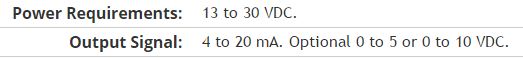
Pressure sensorHere's the DAQ data sheet:
Here are my issues:
First of all I don't know what is LO and HI exactly in the DAQ 9219 material.
Second, I don't know what pin code I should connect the DAQ sensor signal wire. PIN 4 or 5 pin? The sensor has three pins, and I guess I should connect the other two wires to the power supply.
Thirdly how to calibrate the sensor. In labview choose voltage in the wizard?I'm pretty new in this acquisition of data and I need your help.
Thank you
Hi SilasIII,
Hmm well 3 sons are probably on the ground, the power and the return signal. The datasheet for the sensor says:
First of all, you need to know which model you have (4-20mA, 0 - 5V or 0-10VDC). HI refers to the return signal, LO essentially means the land of the food that feeds the sensor. Then, you must get the 13-30 VDC supply. I don't think this should be too complicated and can be a simple wall DC power. You can learn how to create a custom in DAQmx scale. I hope that this is a starting point.
Kind regards
Eric
-
Generation and acquisition at the same time, acquisition of data USB-6356
Hello
I have a VI how is able to read entries with a USB DAQ-6356 and I use a generator of signals 'Agilent 33522 A '. I want to generate and acquire with the acquisition of data.
In fact it works but not well, the frequency is not very stable and does not stop the 2nd loop with 1 (2nd is generating, 1 is Acquire).
Thanks in advance

P.S my VI isn't a state machine true because I need to fight against it at the moment.
OK, so you're at 3 ms/s in writing and reading at 1.25Ms / sec and you wonder why he has a little difference in the frequency set? Ideally, you want to read and write to share a sample clock but by selecting at least the same frequency clock (or one that is one multiple of the other) would go a long way to fixing this source of your error.
The second source of error: you generate a contineous waveform. unless you select 'whole number of cycles' there is a discontinuity when the end is reached at an arbitrary phase and the phase is reset to zero at the beginning of the wave. DAQ assistant writing can "Use Waveform Timing" to adapt its sync settings to the dt waveform and the number of samples.
-
How do the time difference between two dates?
Hi all
I use this query to get the time difference between two dates.
Select to_timestamp ('2012-10-03 12:00 ',' YYYY-MM-DD hh)-to_timestamp ('2012-10-03 11:00 ',' YYYY-MM-DD hh) as double diff;
but do not get the correct result.
Thank youLeft KEY... Left Padding of tanks.
-
Read for the acquisition of data entries are overwritten
Hey there
I have a Daq reading input in a spreadsheet file
Data acquisition was told that one is supposed to have some time a loop around it and I cannot get it to run without one, so good
But my main problem is that it means that it replaces my written file each time that the loop repeats
He also asked me to choose the file to write in several times
How would I go about fixing this?
Thank you
Yes, you can convert digital to the chain, check the attached VI. I recommend you to go through the basic materials of LabVIEW and also play with example of NEITHER which comes with LabVIEW. Remember not to use the attached example and the acquisition of data, always use separate loops.
-
We send 5v data acquisition using a voltage generator. Hook us it up to a voltmeter and see 5V. When connect us the generator voltage to a valve "normally open" parker, the voltmeter indicates .14V. It seems that when we connect the two sons of the valve for the voltage generator, the son act as pattern. We want to control the voltage flowing to tap through Labview. We checked the wires to the valve and they work very well, because if we send a constant 5V since the acquisition of data and put ashore, she, the voltmeter indicates 5V. Someone knows why the son act as pattern and low blood to .14V?
nsatpute wrote:
Our data acquisition is NI USB-6259. The valve requires only a 5V max and our DAQ provides up to 5V. However, after connecting the valve to the acquisition of data, the grave tension to almost 0. We start from the principle that the son somehow act as the reason, but we are not sure if this is the case.
The question here is not how much voltage the valve wants, it's the current needs of the valve. The 6259 can put only 5mA via an analog output. Your very likely tap needs much more than that. If you need to add in an amplifier circuit that can supply more current to operate your faucet.
-
Operating system: Windows XP
Hardware: PCI 6259
Terminals used: PFI0 and PFI2
Counters used: Ctr0 and Ctr1
IM developing an application for the acquisition of data where timed loop synchronization source comes from my PFI2 (using the string A of an encoder). IM basically trying to acquire data based on the number of ticks from my encoder. For the synchronization source, I use counter 1 to capture the rising edge and have the loop time-acquisition of data. At the same time, Im using the counter 0 to count the number of rising edges so I know exactly in what tick data was acquired. PFI0 and PFI2 are connect to channel A of the encoder.
Questions:
Timed loop acquires data at each tick, because when I discover the data (text) file is missing count of my encoder value. Is it because there is a limitation on the Windows operating system? I used a noculars to measure the frequency at the maximum rotation of the channel encoder and 6,757 kHz. All solutions?
Also, is there anyway I can route the source channel internally an encoder to generate synchronization source instead of using another counter? I have attached my VI.
Hello
All the samples that you acquire will be read by LabVIEW in a sequential manner. Figure 4-21 on the M-series on page 80 (4-34) shows that you will acquire all the samples you request all channels that you enjoy in sequentially.
-
Difficulty to read the instrument of series and acquisition of data simultaneously.
Greetings,
I have some trouble getting my VI read from my data acquisition and instrument of the series at the same time. If I run the Subvi simultaneously (i.e. subANG runs in a window and subVEL is running in a second window) both return the correct values and behave as I expect. However, if I call the Subvi in a society mother VI and try to run them both in the same loop structure subANG gets stuck and won't be reprobed with a signal change.
I also tried to use a stacked sequence or plate to separate the execution of subVEL and subANG, but I still get no response to subANG.
The point is is that, if I run Parent.VI in a single window and then creates a copy of subANG (call it '--copy' or other) and run it in a second window, Parent.VI behaves properly and will update the readings as they appear in '--copy '.
I enclose 3 files.
(1) subANG.VI - this bed an an inclinometer RS232 signal. The signal is refreshed every 10ms or more.
(2) subVEL.VI - this bed raw tension of a channel on the acquisition of data, calculates the average then that converts into a pressure difference and finally a speed based on the pressure and temperature inputs.
(3) ParentVI.VI - they simply call and displays the Subvi
My guess is that it's a buffer problem, but I am confused. Someone out there in Labview Earth knows why this might be happening? Suggestions welcom.
It is not an instrument of series. It is a UEI PowerDAq with their typical A/D and the cable.
I found away to make it work by placing subANG and subVEL in some time different loops side by side in ParentVI.
-
Restarting a task for the acquisition of data inside a For loop
Hello
I need iterate through my acquisition of data. Currently, I'm doing this through the creation, implementation and tasks for the acquisition of data inside a loop For which is iterated according to the needs of compensation. Unfortunately, the creation of these DAQ tasks slow down my code.
I would like to be able to create the tasks outside the loop, pass them in and revive the tasks at the beginning of each iteration. Is there an easy way to do this?
Otherwise, is there a way to make the standard DAQmx digital startup trigger trigger several times (so that it starts each pulse data acquisition in a long pulse rather than just the first pulse train)?
Thank you!
-Evan
I whent before and created this example for you (and many others.)
Maybe you are looking for
-
Hi, I have the iPhone 6 and have done since late January. Siri seems to play now. At the beginning of today it does not at all as when you talked to him, he could not recognise all the sounds. When you speak to Siri and the bar moves with your voice
-
Hello I have an iMac 27 "3.4 Ghz Intel Core i7 (November 2011), OSX 10.11.6 Since I have the pain my eyes (working too in front of the screen, even with low light and black background), I change the profile of the screen (System preferences/display/c
-
File missing for the image of the office - so cannot delete!
Hi all I like the image of the desktop to select random pictures, but eventually he travels to present an image of an old Mac OS "crystal cave" - that seems very pixely and terrible, and he stayed stuck and will not go. I have searched for it with a
-
Satellite C70D - how to start from the DVD
HelloYou just bought a Satellite C70D with Win 8.1. Everything works (as much as I know to knowledge), except start it from the DVD. I disabled the Secure Boot in the bios and changed the boot order on a DVD first, then USB and HARD drive. The DVD pl
-
Satallite L300D crashed on me last night and won't restart
After it crashed I tried to reboot it went to the windows repair but then stops at a screen with x:\Windows\system32\drvload.exeIt has a blinking cursur but don't let me do anything. I tried using the recovery disks, but it just goes to the windows,