Acquisition with USRP 2953R of the GPS signal
Hi all
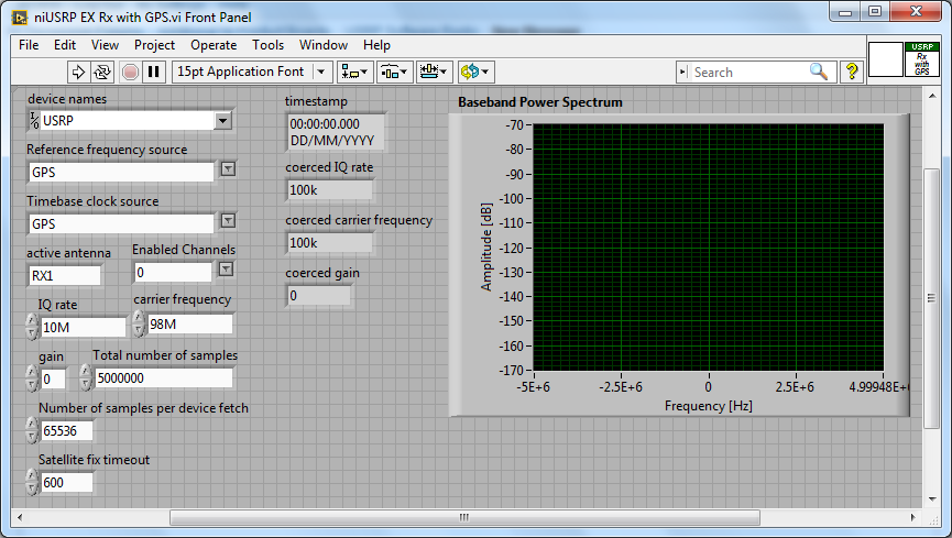
How can I configure a 2953R USRP receive GPS signals? I have an antenna VERT900 connected to the GPS ANT of the USRP port, but in the example VI 'niUSRP EX Rx with GPS', I can't reference this port in the field 'Active antenna'. I put only things like TX/RX or RX1 etc. Should what values I put in other areas as well? I know that the L1 band is 1575,42 MHz.
Hello
The example you posted shows you how to acquire an RF signal on the ports of the USRP with internal clock RF and sources of reference defined in the GPS.
To make it work properly, you must have a GPS antenna connected to the Terminal on the GPS device and installed in a place that receives a good level of GPS signal.
The other control of antenna on the schema defines the port on which to receive the RF signal.
If you want to capture and analyze the signal GPS (RF) itself, you can tune into the front-end RF (carrier frequency) at the right frequency of GPS band and connect your GPS antenna to the RF port.
You can use the simple niUSRP EX Rx continuous Async.vi in this case (but may not work due to the very low consumption of GPS RF signal)
Tags: NI Products
Similar Questions
-
Smartphones from blackBerry Curve 8520 - Blackberry MAPS - how/where can I configure the GPS signal?
I took a brief look at the questions on the CARDS, but none of these go to the ART GPS end does not. (I'm sure it's somewhere in the support forums, but I found nto).
I have the icon of the WAP on my Blackberry Curve 8520. But when I click it I don't see is a grid nd no card. I checked Options Options/Advanced/cards and it is said by default Blackberry MAPS Service - EU. I also checked the place settings and under GPS Data Source it comes up with a list of all my contacts id bluetooth I suspect this is where it goes wrong, but I can't be sure.
How can I put the correct GPS data source. How/where can I set this up please. ???
Thank you
JJ


Any other ideas as to why the Blackberry connects sometimes to devices and sometimes does not. I saw him sign for a brief moment especially for my GPS dongle. Then fell to new. The signal on the dongle seems it continues to blink.
When I take my BB in my car it instantly takes the car blue tooth
Don't understand why he doesn't connect properly on my GPS unit now.
-
Calibration frequency Offset transmitter and receiver with USRP® material
Hello everyone, I read the scripts provided by The Mathworks on the frequency of calibration offset transmitter and receiver with USRP.
The USRP® transmitter sends a sinusoidal signal at 100 Hz with the MATLAB, sdruFrequencyCalibrationTransmitter.mscript, the USRP® receiver. The USRP® receiver monitors the signals, calculates the transceiver frequency shift and displays in the command window MATLAB for calibration with the MATLAB script, sdruFrequencyCalibrationReceiver.m. At the level of the receiver, frequency offset will be calculated and displayed in the command window. The program uses a Spectrum Analyzer to show the spectrum of the received signal. In the program, the corresponding sentense is '% display frequency spectrum. step (hSpectrumAnalyzer, rxSig); "Based on that, I thought that the spectrum analyzer would show the spectrum of the received signal. However, the Web site corresponding site shows "to compensate for a shift in frequency of transmitter/receiver, add frequency offset on the Central frequency of the receiver object SDRu system. Be sure to use the sign of the offset of your addition. Once you have done this, the spectrum displayed by the Analyzer of spectrum of the receiver system object must have its maximum amplitude at about 0 Hz." What I'm confused is, why the Spectrum Analyzer should have its maximum amplitude at about 0 Hz, not other values? Is it because of the characteristics of the USRP itself or the Analyzer of spectrum shows is the value of the difference between the Tx and the Rx after calibration? I use neither-USRP 2920. Your response will be much appreciated! Thank you!
The matlab mfile is found in the following links:
Yes if two devices are not locked to a reference clock, 10 MHz for the USRPs you will see a shift in frequency.
Specifications in ppm, ppb can give you how it can be:
http://digital.NI.com/public.nsf/allkb/2A0B9D3F365DEDEF86256BDB007354EDBye!
-
The GPS data with other analyzed data record
Hello!
I am a new user of DASYLab and not very good with coding, so please bear with me! I try to record (timestamp, latitude, longitude) already analysed GPS data with other data (accelerometer, etc.) in the same. DDF file. Right, GPS analysed is now sent through a series of three demultiplexers for each signal and only 1 of 16 channels, reducing the size of the output data. This data is then saved in a. The CAD file. Other data on average, recorded in one. DDF file, then saved another. The CAD file. We used to compare the data from the GPS and other devices by comparing timestamps.
I would like to save all data to a file, either. DDF of. CSA (.) DDF would be preferable).
When I try to add more channels in the. DDF save the module after the demultiplexer black box and GPS data to it, I get an error saying "the data to an entry in this module are the wrong type." I also receive this error when trying to send the data GPS to the. CSA Save module. I learned that this means that the size of the files is not the same of this thread. My question is, how can I make sure that the data have the same characteristics of time so I can save to the same file?
If you need more information I would be happy to provide it, I apologize if I have something important to go.
Thanks for reading,
etdiv
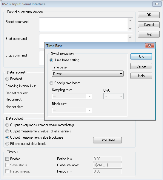
That's what I needed. Your time is the driver. In the RS232 input module, click the Options button.
Select the measurement of output value, and then click the button on the time Base and select sync/time Base driver.
That should allow you to write to the DDF file.
-
my iPhone 6s has problems with the GPS when I use some applications, it does not work well and give especially the bad road. Can someone help me?
My iphone 6 has started having the same problem. Its literally the GPS. Saying that it does not find me at all. Ive seen say location for more than an hour in the suburbs of chicago. It started to happen to me after I downloaded the latest update for the iphone. I hope they react and let you know what is happening because I'm dying to know as well.
-
AZ1VR Action Cam Mini with a Wi - Fi connection is the GPS integrated into the handpiece
I have the new AZ1VR Action Cam Mini with a Wi - Fi is the GPS integrated into the handpiece
cannellaj wrote:
I have the new AZ1VR Action Cam Mini with a Wi - Fi is the GPS integrated into the handpiece
Yes, get the GPS with the AZ1 to remote LVR2V wrist. You must also update the firmware in both devices. I have both and they work great.
-
How to stop the acquisition with a relaxation with the NI PCIe-6323
Hi all
I wonder if it is possible to stop data acquisition or pcie-6323 with a trigger pulse the same way that I begin to acquire samples with a finished sample mode trigger pulse.
Thanks in advance
M.
The samplesPerChannel that you can show what the sample clock configuration defines the total number of samples for the acquisition of finishes. In your case, you will read the data previously triggered so permanently in force this setting really only sets the size of the buffer. If you want to just be large enough to avoid overtaking (although...) If the window you buy is potentially very short, you might want to explicitly configure the size of the buffer to something bigger and maintain the value of samplesPerChannel down so that the reference trigger can be accepted earlier).
The numberOfSamples you specify when you start the player defines the number of samples for the next call for reading. If you can read the small windows of streaming data to avoid having a blocking with a large timeout call. If you do not want to change the time-out period, it is a property of the DAQStream class.
The "continuous" examples (e.g. this one) should show how you can read back data asynchronous as it is acquired. Your configuration looks more like a "continuous" example
Since you want to start and stop using the same line as the trigger, perhaps an alternative to the evolution of the default read pointer would be to set up a central task of analog input with a relaxing break. The caveat to this is that the break does not stop at the task and as soon as the line goes back to you will begin to acquire the data again - I would say using a meter to separate groups of samples in the buffer zone continued. If you wish to purchase multiple windows of data in short succession well, then I would go with that instead to avoid having to restart the task (and potentially Miss samples during the restart of the task).
Best regards
-
[FPGA] Problem with the sinusoidal signal generator
Hello!
At first I want to apologize for my English is not my mother tongue.
Hardware and software I use is:
LabVIEW 8.5
NEITHER RIO 2.4.1
NEITHER cRIO-9014 (controller in time real CompactRIO)
NEITHER cRIO-9104 (chassis and FPGA)
NEITHER 9264 (16 channels, +-10V, 16-bit voltage analogue output Module)
I made a very simple FPGA VI: a while loop, generator of sinusoidal signal and a FPGA of e/s node in the loop. I've specified the Gnerator settings by following the path:
Frequency = 50 Hz
Amplitude = 1
Phase shift = 0.00
Size of the table look-up = 1024
= 16-bit amplitude resolutionFPGA clock frequency (40 MHz)
But the wave of "sine" I got is not what I wanted to get. First of all, its amplitude is 1 V. shouldn't it be coded on 16 bits? If I wanted to get 1V I should have specified Amplitude as a 3277. In addition, 'sine' is not very detailed, it's look like "steps", as many samples vere missing. What I did wrong? I checked the samples and tutorials, I did everything the same way. A I forgot something or not has not specify other parameters?
Thanks a lot for your help!
OK, I solved a problem. It's embarrassing to admit, but maybe this will help someone else
 I blame my inexperience
The main solution to the problem was changing calibration of calibrated RAW Mode. After that, everythoing works as expected. I had a problem with a sample because I was using a multiplier to control the generated sine wave amplitude. But... She was set to 1 in the sinusoidal signal generator. That was the reason for waveform Gradin. Please, don't laugh too much

In any case, thank you for an answer! It is now resolved
-
order a fan with USB6251 and the Daq signal accessory
Hello
I have a school using Labview project and the USB6251 connected to the Daq signal accessory card.
The Labview program must read continuous temperature (Ia 4 channel, internally) temperature probe connected to the accessory of Daq Board signals. When the temperature reaches an established value, then a led on the front panel should be lit and a singal output data acquisition should start a fan connected to the acquisition of data which cools down the sensor, then stops.
Would it not be possible to do something like that? Even if I generate a square signal and the fan only works on the State of the signal. The fan requires at least 120 mV DC current. I'm afraid that if I take these courses for the acquisition of data, I could damage the unit.
Thank you.
I guess you mean 120 current my DC
. If you look at your spec of daq card, you will find that the current max are far below 120 my. This applies to the two analog out and digital out. Take a look at this site, it may be useful to some. site nice http://www.me.umn.edu/courses/me2011/robot/TechNotes/motorcontrol/motorcontrol.html . If you want the speed controller, you have two options PWM or voltage of the motor regulation.Good luck
-
Problem with the biphasic signal generator
Hello!
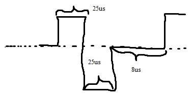
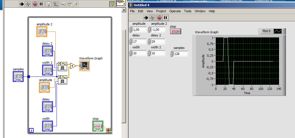
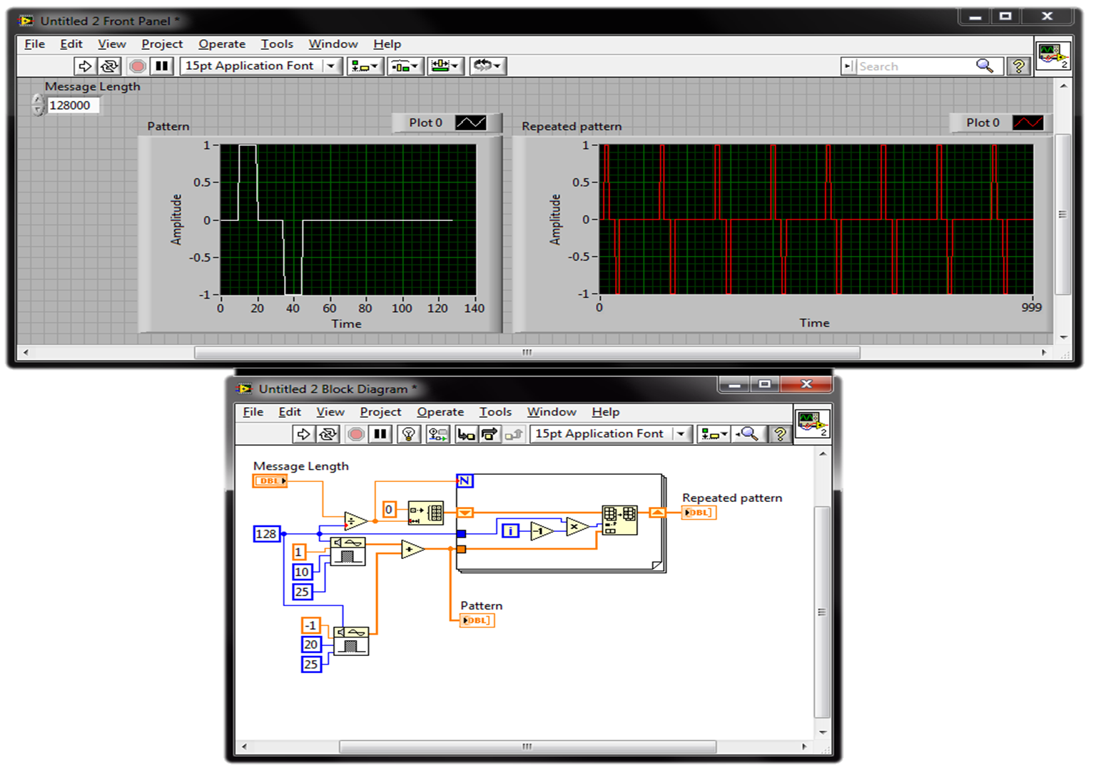
I filtered signal and detected envelope with OATS envelope detection.vi of given length. And now I need to modulate signal biphasic (photo). The biphasic signal should be the same length as my envelope signal. I want to be able to change the width of peak (25us) time and period, frequency (1 kHz), the biphasic signal amplitude (1). I know that I can start with pulse pattern.vi (check my diagram). But I don't know how to put together it me give only a single period. I have LabVIEW 2013.
You can repeat your profile of signals using a loop. Keep in the Middle the number of times where the model is repeted depends on the length of the theme of your message and the sampling frequency, you use the model and the message. Check this picture (just a quick suggestion):
best,
-
Power of the weak signal with my wrt54g
My wireless router has been uneven, since my cable company installed a new internet cable modem. I powercycled several times, downloaded the new firmware, rebooted and still have problems. Lately when I finally get on the internet with a wireless device, the signal is very weak. It is low on my iphone on my Mac laptop and also on my Samsung Bluray player. Lately a window never ceases to appear when I'm watching netflix who says my bandwidth is too low, even if he works very well for 2 months. Is my router obsolete?
No, it is recommended to have security enabled. Does affect your signal strength when you activated? If this is not the case, go ahead and re - activate.
-
BlackBerry Bond serious problems with the GPS on BB jump with OS 10.3.1
Hello
I have 3 problems with my BB jump; for 1 of it, I write here a solution.
When I get on the maps of BB (installed by default) with location and a Wi - Fi enabled connection, my position still show that I'm somewhere in Basel (Switzerland), even though I live in other countries European. I tried the settings, and I can't find anywhere any preset location. Is it not strange that the GPS is not able to find my REAL position? Please let me know what I can do to be legitimate spotted.
the other secondary issues which I hope will be resolved with upgrades:
1. the sound of the keyboard cannot be completely reduced, even if the sound is at a minimum.
2. the sound of the camera has no parameters to kill noise when shooting.
Thank you.
citizen_ka wrote:
It is true that I didn't try the device under the sky :).
Well, there you go. Go outside with a view of the sky, no buildings.
What part of the world, what country are you?
citizen_ka wrote:
the volume is set to minimum maximum and still makes audible clicks when entering.
Minimum only.
-
Check the Wifi signal with 'wifi_get_status '.
It's the code I use to check the wifi signal, this is the first time, but now it is far from the WE even I turn off the wifi. Please help me with this problem. Thank you.
bool checkWifi(){
    wifi_status_t status = WIFI_STATUS_RADIO_ON;
    int i = wifi_get_status(&status);
    if (i == 0)
        return true; // Wifi On
    return false; // Wifi Off
}
Hey there...
You integrate an incorrect value...
bool checkWifi() { wifi_status_t status; if (WIFI_SUCCESS == wifi_get_status(&status)) { if (status == WIFI_STATUS_RADIO_ON) { return true; } } return false; } -
Wireless network connection is connected with the strong signal, but stops working at random times
Original title: internet says is connected with the strong signal, but stops working at random times?
Hello
For the last few weeks, I had problems with my internet connection. Wireless connections say I am connected and have the strength of the excellent signal. I know that this is not an ISP problem because my other computer works fine. I will be reviewed fine and then all of a sudden, the site doesn't load any more, although I'm always connected to the internet. This happens on Firefox and Internet Explorer, this isn't a browser issue.I read other offered on the internet and tried all, but nothing has changed. I have checked proxies, disabled antivirus and installed new, checked firewall, ran a check for malware, etc..
Any help will be much appreciated because it becomes very frustrating to have to keep reconnected my internet when he says he's working.
Hello
I suggest you follow the links below and check them with the question:
Method 1:
Step 1:
Start your computer in safe mode with network and check the number: http://windows.microsoft.com/en-US/windows7/Advanced-startup-options-including-safe-mode
Step 2:
You need perform a clean boot to prevent any third party conflicting application from interfering with your computer.
To put the computer in a clean boot State, you must follow the steps in the article mentioned below and check with the question.
How to troubleshoot a problem by performing a clean boot in Windows Vista or Windows 7:
http://support.Microsoft.com/kb/929135Note: You must follow step 7 of the article mentioned above to recover your computer to a Normal startup after you complete all the steps.
Method 2:
Uninstall and reinstall the NIC drivers and check with the question.
a. click on Start menu, in the Search tab type devmgmt.msc and press ENTER.
b. right click on network adapters, and then click on uninstall and restart the computer.
c. after rebooting, install network cards and check with the question.
For reference:
How can I troubleshoot network card? :
http://Windows.Microsoft.com/en-us/Windows7/fix-network-adapter-problems
I hope this helps.
-
Problems with the GPS unit connection
I have a Garmin Nuvi 650 GPS device.
If Windows is at the front and I plug my GPS using the USB cord, the GPS is displayed on my Mac desktop.
If I go to Fusion > Virtual Machine, the mouse down to USB I can mouse horizontally to highlight the GPS and can then process in Windows.
However, as the Garmin is recognized by Windows, it disappears from the Mac desktop computer and I get the alert that a device has been incorrectly removed and may be damaged.
In what order should I do so that the GPS is "captured" by Windows and never appears on the Mac desktop?
BTW, when I'm done with the GPS in Windows and unplug it, it reappears again on the Mac desktop.
Thank you
Biker BobVMware Fusion 2.0.1
Windows XP SP3
OS 10.5.6
--
__o
_ \ < _
()/()
It all seems normal and expected. You can get get the unit appears directly in the comments by turning on auto-connect USB (which is enabled by default, but doesn't seem to be in your case) and connect the nuvi when the virtual machine Windows has focus. Alternatively, to avoid the warning of OS X, you can eject the nüvi to OS X before connecting it to the guest.
Maybe you are looking for
-
Hi all Is there any application for registration of free calls to Iphone? Android supports a lot of apps, devices last windows 950 also built App. Why cant IOS support?
-
Could not load the driver for Teredo Tunneling Pseudo-Interface
Hello Does anyone know how to fix this problem (Vista) Business ProductTeredo Tunneling Pseudo-Interface ProblemCould not load driver software DescriptionWindows was able to successfully install device driver software, but the driver has encountered
-
Hello I'm working to deploy a group of 1242AG APs with a 12-4402. I'm looking to use LWAPP and run the WC in mode layer 3 with deployed on a different subnet access points. I tried to assign an address (and 43 DHCP option for the IP address of manage
-
I blustered on this forum about some issues with Adobe Muse but I'm here to express my gratitude for the Adobe team Muse turning in an impressive we dev platform. It's now my leading platform in the development of anything on the web. I just finished
-
I have a plan of the Basic $9.99 monthly photography and when I went to access photoshop it tells me that my trial has expired?