Addition of alarms in real time
When I go to alarms in real time, I get; No VKernel capacity alarms are active for this part of your environment at this time. In the window. However I don't see how I can configure these alarms. I know that of course could practice yesterday evening as one of our web servers went from 3MB or RAM to 8 MB in less than an hour and it locked up. It would have been nice to catch that.
Is there a process to activate alarms in real time?
Kevin, you're partially right that I discovered yesterday. VoP team did a webex with me as it seems when I installed VoP exploerer and connects for the first time, I got an update. Well, the update has been updated standards. Surprise to us all and that they are looking into that. That said, they activated the alarms and everything set up... I have nothing to be alarmed about. As you can see from the following screenshot, the alarms are enabled in fact.

The trend alarms are activated. Some of these features, they will disappear when my trial license is in place for server and things restores to explore. They were a little confused on the upgrade and don't update. Whatever it is, I have a chance to play with some automation and present a good documentation and analasys for my cost management. More than I expected. Thanks fo much for jumping on and trying to give me a hand with this.
I even went a step further today and built-in AD to our Admin group and all involved are to love him now.
David
Tags: Dell Tech
Similar Questions
-
MacAfee says real-time internet security disabled during access via Firefox.
Although the Green OK of MacAfee sign illuminates when accessing e-mail in xplornet.ca via Firefox (my default), a message tells me that MacAfee real-time protection is disabled. By clicking on the button 'Activate' returns me seconds to red alert "off."
This has happened
Each time Firefox opened
Hello Mark.
Well maybe not related to your problem, I have to remind you that the version of Firefox you are using right now has been deleted and is no longer supported. In addition, he has known unpatched bugs and security problems. I invite you to upgrade to the latest version of Firefox, for maximum security, stability, performance and ease of use. You can get it for free, as always, to getfirefox.com.
What about your problems, you must contact McAfee support.
-
For a sequence in real-time output variable
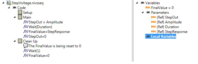
VS 2011, I have a sequence of real-time voltage step that sets an AO for a voltage given for awhile, and then resets the output to 0.
Just before setting the output to 0, I want to read the response of my this stimulus of an AI System I call StepResponse. To do this, I place this in FinalValue I set as a Variable in my script. In other words, it is a parameter or a local Variable.
Now, how can I get this out FinalValue? I don't see anything on how to "test" this variable to one of my user variable... I was able to do with the stimulus inherited in VS2010 Editor. Now, I'm stumped.
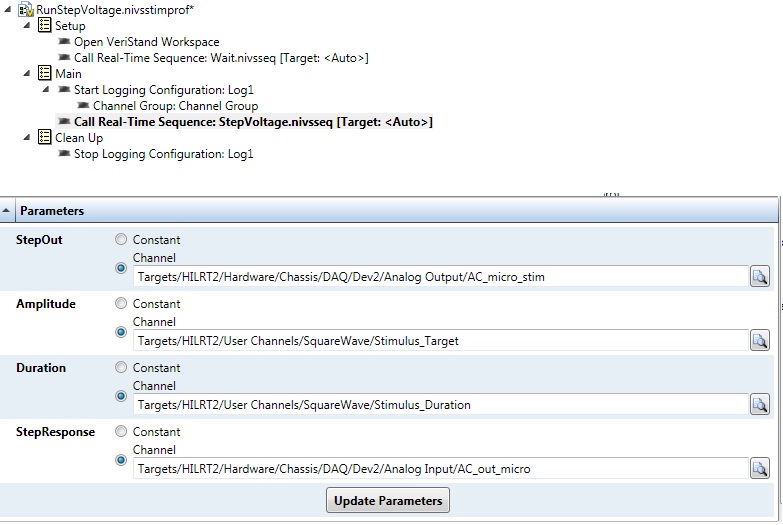
Here is the sequence:
and this is the profile of stimulus and settings below. I can set the fine settings via the API of LV, or run the Publisher of the Stimulus. But I can't seem to get out this FinalValue...

THX.
L.
The return for a sequence (in your case FinalValue) variable is returned to the caller once the sequence has been completed as a result of this sequence. In your example, the appellant is stimulus profile that you configured. In a profile of stimulus, two relevant things will come based on the return value of variable a sequence called:
- The return variable value will be get recorded in the file of test result ATML for stimulus profile
- You can configure an assessment of output for the call to test sequence make a basic on the return variable test to determine a pass/fail result. For a numeric variable to return such as FinalValue, you can do a check of numerical limits to test whether the value is in or out of the specified limits. For a Boolean return value, you can translate either directly in a pass/fail result, or you can reverse the logic as well as False implies Pass.
In addition, the LabVIEW API has a function, you can call once the sequence finished to programmatically retrieve the return value.
However, in your sequence after that you store the value StepResponse in the return variable, you reset to zero before the end of the sequence. If your sequence always returns zero. I think that you do not remove this line and let FinalValue what so that you will get the StepResponse back closure instead of zero value.
-
Control of data using multiple thermocouples via indicators and the waveform in real-time
I apologize in advance for this question is probably a bit simple but I'm all new to labview and the forum and could use some advice. I have a CompaqDAQ with two 9213 16 modules of track and I'm trying to read in 30 thermocouples in a waveform, but also display 30 indicators so I can mark each indicator with the thermocouple for real-time tracking. Each thermocouple corresponds to a specific location and it is essential that the interface has an accurate indication or a label for each of them. I wonder if there is an easy way to do this in addition to split the signal and have 30 thermometers on my diagram? Perhaps a table any? If I use a table to create 30 thermometers, the DAQ assistant automatically sorts the thermocouples according to ascending numerical order. For example, would be the indicators of first and second on my interface automatically assigned to channels a0 and a1 of the first module, or should I do it manually? Even for the waveform? Thank you very much!
PS - Do not know if this message had need of more details, but let me know if more information is needed, and I'll give you!
I see that you use the DAQ Assistant to create your task. Now I understand why you may have about labelling. It is easy of the seller NOR spiel booting... But in any case, you already have a task to the MAX instead of use the DAQ Assistant? The interface is similar and there may be a step or two, but your end application will be more effective and you will have more options with your data and properties. For example, I tried to update the names of physical channel in the DAQ Assistant installation program, that it let you do, but it propagates that change forward to waveform chart legend. Also, I don't know any property for this dynamic data type node, although I never use it either. I suggest the setting up of your task and channels, Max if you'd give it a go.
Since I thought I didn't really takes you all the way with you help, I wrote another one. It uses a cluster, even if it's a bit barbaric. I thought that there was a more eloquent way to do by changing labels, but I could not it works as I had expected.
-
We want to start by using the Toolbox in real-time to backtrace of memory allocation profile on a target of cRIO 9035 & 9039.
The product information (http://sine.ni.com/nips/cds/view/p/lang/nl/nid/209041) page has a note indicating that the Toolbox has limited functionality on real-time OR-Linux supported targets.
However, I couldn't find any specific details about what are these limitations.
If anyone can clarify which restrictions apply?
Are there alternatives (party packages) that offer a feature more complete?
Hello Jörn,
Did some more research, the following limitationrs occur on targets LInux RTOS,
-The Manager of memory when used on targets of Linux, saves only data for LabVIEW processes and threads, not the global memory of the systems.
-Wait object are not recorded events
-Trace buffer size cannot be changed
-Timed loop pre-emption and reactivation of SRI events are not markedHope that this information helps out you in addition,
Kind regards
-Natalia
Technical sales engineer
-
make a graph in real time of 1 DBL value at a time, using a loop for
I have a somewhat interesting programming task where I have the following situation: (I have attached a mac version of vi Labview 2013)
-Using a patented (pre-made and uneditable) sub - vi, who receives a value of 0 or 1 as input and reads off a single measure, whenever he receives 1 while a value of 0 is necessary to 'reset' of the vi to rehearse a new measure.
-I would like to run this sub - vi repeatedly in a loop For each value of "measure" are sent to a curve of waveform to give a direct value (real time) for the graphic to display.
-As it is, I have a vi file that simulates action in a loop but built in a 1 d array to get exuent values sent a waveform curve.
-I don't know how to make a real-time graph which receives 1 value double both.
-In addition, I want only every 2nd value sent to the loop for, but I already have several ideas on how to do it. First of all, I am concerned about the target in real time.
Kyle Shiel
A graphic, not a graphic, allows you to update a point at a time. It would be inside the loop for. update the chart or not, you can use a select statement or the structure of the case.
These are pretty basic functions in LabVIEW. Please see the free tutorials.
-
Algorithm of PID in 'PID and Fuzzy Logic Toolkit' and 'real time Module ".
Hi all
I am recently using LabVIEW 2011 and 2011 real time Module. My application requires the PID control.
Now, I have a problem. In the manual for "And Fuzzy Logic Toolkit PID", Chapter 2 "algorithm PID" it indicates non-interactive algorithm (also called the ideal algorithm, Standard or ISA) be used in all the screws of PID in the Toolbox. It seems that Yes from source code. However, in Chapter 3, "Using the PID software" arrays of calculation of PID parameters based on method of Ziegler-Nichols, which was developed for the interactive algorithm (also called the series, the real classic algorithm). D action has been included in the scheme of control, the settings may be different for the two algorithms. In fact, Cohen Coons and adjustment PID Lambda rules can be used for the algorithm used by the box tool with no conversion.
In addition, there is a PID function block comes with the real time Module, and I know not what PID algorithm it uses. Can someone help me?
Thank you in advance.
Su
In the "and Fuzzy Logic PID Toolkit, we use the University structure to implement all algorithms. Tuning techniques we show on the manual to express the original work and we try to keep the same as you would look at the literature. However, in our implementation of autotuning internally converted to the structure used by our algorithms to keep compatibility with our own implementation.
If you use an external source, you can use the Conversion.vi of Structure PID to change University, parallel or series of parameters in one used by our algorithm.
The PID included with the real time module is a 'copy' of our algorithm, and they have the same settings and behavior. The only advantage to use this function block, you have access to the parameters through variables.
Hope this helps...
-
How do I get the analog input signal and send it to output analog (real time)
Hello world
I do a simple task in Visual C++ and I use PCI-6221(37 pin).
Basically, I want to send the same signal of "analog input" to the "analog output".
at the same time (or almost), to make real-time application.
Can someone provide me with sample program please.
I would be grateful if you could provide me with the great tutorial that explains
step by step everything about NOR-DAQmx for C/C++ programming.
Best regards
Khassan
This is my code in C++, you can optimize it if that seems too messy. This code reads the analog input signals and exports it through the analog outputs.
To make this code additional work of the directories include and library directories must be added to OR.
I hope it helps someone.
#include
#include
#include "NIDAQmx.h".
#include#define DAQmxErrChk (functionCall) {if (DAQmxFailed (error = (functionCall))) {goto error ;}}
int main (int argc, char * argv [])
{
Int32 error = 0;
TaskHandle taskHandleRead = 0, taskHandleWrite = 0;
Read Int32 = 0;
float64 context [1000];
char errBuffRead [2048] = {'\0'};
char errBuffWrite [2048] = {'\0'};
bool32 done = 0;
Int32 wrote;DAQmxErrChk (DAQmxCreateTask("",&taskHandleRead));
DAQmxErrChk (DAQmxCreateAIVoltageChan(taskHandleRead,"Dev1/ai0","",DAQmx_Val_Cfg_Default,-10.0,10.0,DAQmx_Val_Volts,NULL));
DAQmxErrChk (DAQmxCfgSampClkTiming(taskHandleRead,"",100.0,DAQmx_Val_Rising,DAQmx_Val_ContSamps,0));
DAQmxErrChk (DAQmxCreateTask("",&taskHandleWrite));
DAQmxErrChk (DAQmxCreateAOVoltageChan(taskHandleWrite,"Dev1/ao0","",-10.0,10.0,DAQmx_Val_Volts,NULL));
DAQmxErrChk (DAQmxCfgSampClkTiming(taskHandleWrite,"ai/SampleClock",100.0,DAQmx_Val_Rising,DAQmx_Val_ContSamps,1000));DAQmxErrChk (DAQmxStartTask (taskHandleRead));
DAQmxErrChk (DAQmxStartTask (taskHandleWrite));While (! fact &! _kbhit())
{
DAQmxErrChk (DAQmxReadAnalogF64(taskHandleRead,1,10,DAQmx_Val_GroupByScanNumber,dataRead,1000,&read,));
DAQmxErrChk (DAQmxWriteAnalogF64(taskHandleWrite,read,0,10.0,DAQmx_Val_GroupByChannel,dataRead,&written,));
}
_getch();Error:
If (DAQmxFailed (error)){
DAQmxGetExtendedErrorInfo (errBuffRead, 2048);
DAQmxGetExtendedErrorInfo (errBuffWrite, 2048);
}
If (taskHandleRead! = 0){
DAQmxStopTask (taskHandleRead);
DAQmxClearTask (taskHandleRead);
}
If (taskHandleWrite! = 0){
DAQmxStopTask (taskHandleWrite);
DAQmxClearTask (taskHandleWrite);
}
If {(DAQmxFailed (error))
printf ("error DAQmx: %s\n",errBuffRead); ")
printf ("error DAQmx: %s\n",errBuffWrite); ")
}
printf ("end of the program, press the Enter key to quit\n");
GetChar ();
return 0;
} -
RT - set the time of real-time target in MAX
Hello
I want to manually change the time on my target in time real (cRIO-9022) with MAX
I followed the steps described here.
In step 2, when you install the remote system OR 14.5.0 Configuration Support
I get the following error message when you try to install:
"Labview real-time 12.0.1 requires the service locator 1.0".
On the host computer, I had SP1 2013 Labview with the module time real 13.0.1
On the cRIO, I'm under Labview RealTime 12.0.1
I installed SP1 2012 Labview real-time Module on the host computer and tried 12.0.0.
Then, I received this message:
"Remote Server for Labview RT 13.5.0 requires Appweb 13.5.0
Engine for Services execution Web 13.5.0 requires NEITHER System Web Server 13.5.0
LabVIEW Real-time 12.0.1 requires the service locator 1.0 ".
I searched the forum with no luck
Any help I appreciated.
BR
Arne M
Hello
I solved the problem.
Just had to select the correct versions of all additional software necessary
Support remote Configuration OR system 5.6.0 etc..
-
Creating a Clone of VI in the real-time platform
Hello
I wanted to create a clone of VI in time real LV on cRIO-9022 controller. I changed the properties to run VI and selected pre allocated incoming running clone.
But I'm unable to generate the clone like this.
I read from here, "you can configure LabVIEW to allocate or share a VI clones reentrant clone shared within a structure ofloop delayed or Timed Sequence" .
My question is how can we create a clone of screws in the RT platform? clones are limited to Timed loops only?
I use LV 2013, cRIO-9022, chassis NI 9114
Thank you
Thibault
Hello
I got it, it was similar to what you do on a normal LabVIEW VI. I expect a change in the name of VI in CloneXXXX.vi, but in real time, I think that you do not have this indication.
As he had no name and when I try to open the instances of these real-time clone live all were directed to the real VI itself, so I thought that it did not work.
but I think that it how it is in real time.
I did a test using the simple addition of numbers using clones and it works very well.
If you do not get the clone of instance names when you open the front door and we cannot highlight the real-time performance clone VI
I think it's obvious.
Thank you
Thibault
-
using NI USB 9201 with LabVIEW Real-time
Hello
I try to use a USB of NI 9201 on a remote real-time target. Here's what I did: 1) tricked out of a desktop PC to serve as target RT using the instructions provided on the Web site of NOR. He now starts in an RTOS with LabView RTOS 9.0. (2) I communicated successfully with the help of a host computer that has a windows with LabView 2009 BONE and I installed the software from the computer remote RT target host using ethernet. However, my problem is when I plug NI 9201 USB on the target RT that I do not see the material listed on the devices tab in MAX and interfaces on remote systems. I tried to get the manuals for the HW 9201, but it seems not much explained here, or maybe I'm looking in the wrong places. Any help is greatly appreciated.
PS: I am attaching 2 JPEGs for additional explanations (tab network settings and the settings of the system).
Thanks in advance,
Benoit.
AVS,
9201 USB is not supported on RTPCs please visit this link. Currently no usb-DAQ devices do not support an environment CRPC. Only the PCI DAQ devices are supported.
-
Output signals controllable DAQmx (real-time)
Hello:
I have a question here.
It is quite difficult for me, and I can't find any bad example and discussion.
Hope that some people give me some information for me to look it up.
--
I am trying to generate an analogue signal into a DAQmx device (I have an and uses it well) to control another device.
The output signal must be the sum of a background signal (which is decided, let's say a sine wave) and another control signal.
The control signal depends on the entrance of real-time control, for example by using the horizontal location of the mouse to the value of the signal.
The background signal is designed in advance and it will run continuously (should not be stopped once the system starts to ensure that synchronization between each devices).
At the same time, the control signal should be continuous. (if there is no new entry, it uses the default value or the last entry).
--
I have almost no idea on how to do it.
As far as I know, needs only one daq task to write the signal, and then she runs after.
The control signal is a thing in real time, so the task needs to be updated very quickly.
But regeneration tasks cost 50ms ~ on my computer (and I used the low levels rather than the DAQ assistant Renault).
Also, in this case, my background/control signal will be be stopped every time that when the task is regenerated (and this makes my synchronization failure.)
I checked DAQmx in real time, but couldn't find a few examples of tris and seems it isn't for my application actually (?).
A possible solution, I came is cascading my two signals once they are generated by my DAQ hardware. And then I can use an a/o to be the background signal and use an another a/o to be the control signal.
However, my control signal is always interrupted between each loop, and the method of external cascade seems not smart.
Or data acquisition is not perhaps suitable for this application?
--
Hope that some people give me some information and then I can check their.
Thank you very much
Hi Jhensi,
How the example provided was for you?
With respect to the delay that you experience, there is always a slight delay incurred as a result of underlying driver DAQmx running in the background.
In addition, your USB 6611 will have inherent delay due to being used as the communication protocol USB bus. There may be up to 100ms latency in some cases with USB 2.0.
This driver requires a certain amount of time to change the type of output signal, that is production.
A user will never really feel a 'Real-time' experience when you use an application that uses DAQmx. Deterministic control applications almost always use an FPGA with a real-time embedded controller.
It is possible that other delays are due to timing considerations in your code but if you checked these it may be a hardware limitation.
If you could let me know how you do that would be great.
Kind regards
-
Real-time application does not work; source code works very well
The short version is I'm programming a cRIO and apparently the RT code isn't running after you deploy, and I can't understand why. It is further complicated as I do all this remote and I don't have direct access to the unit since I am 500 miles away. I work through a couple of other guys who know some LabVIEW, but neither is working on the site so that they explicitly trip there whenever I have a bright idea.
I was there a few weeks ago. During this time, I created a code simple cRIO, since I'm new to the cRIO, allowing the user to move a control and change a chart. It worked fine, but I must stress that it did not have a FPGA component. After that, I worked on the actual code, which reads some sensors, displays the results on a user interface and stores the results. Did FPGA. I used it in the LabVIEW environment and it worked fine, but I ran out of time before I could finish a release build and deploy the RT as a compiled application. I sent them the version later, my contact deployed but had the network stream errors during execution of the user interface.
After hours to address network problems and sending over debug versions, I tried to create a log on RT level so I could see what was going on. The journal is not yet open, even if it is the first command in the code. I have pores through the forums and found http://forums.ni.com/t5/LabVIEW/cRIO-Troubleshooting-creation-and-deployment-of-startup/td-p/1956475... which took a new direction.
I had my contact use the RT debug console and when it pulls up to the front of the RT, it shows an arrow broken at delivery. He clicked and nothing happens - no work, no list of bugs. If he shoots to the top of the list of bugs manually, it is empty. Again, the RT works very well if you run it through LabVIEW and not as an application compiled in real-time. He also noticed that the open FPGA VI was grey on the block diagram. Are no other icons.
If the problem seems to be that the compiled application of RT becomes some kind of error, but do not tell me what it is, and it seems to be related to the opening of the FPGA. I recompiled the FPGA and RT. I recompile the RT himself, but not the FPGA, because this would take hours. It is download everything properly for the cRIO. The RT is set to run automatically. It is restarted the cRIO whenever he deploys the RT. They have LabVIEW on a computer, but it doesn't have the correct drivers to run the code of the environment of LV. I am to resist have them install the dirvers because downloading big files is complicated due to the restrictions of security as well as a lousy connection at a remote site. In addition, it does not solve the problem of RT executable doesn't work is not the same as the source code, which, according to the thread above, seems to be a thing.
The last thing I'm getting is that I sent her instructions for how to build a source distribution of the project that I sent and try to deploy on the cRIO. Even if it works, I'm not sure that this is an acceptable solution, because I assume running VI, rather than the EXE is slower, and they need to speed on this project.
Simply, I don't know where to go from here. I probably need to get direct access to the cRIO and I might be able to convince them to ship to me so I can understand this point, but I don't know where I got same departure other than the Voodoo debugging standard of "trying stuff randomly until something works". I am open to suggestions, if someone managed to solve this before.
Code snippet of the first part of the project is fixed, although I don't know how much what good it will do. I am really confused, and the customer is frustrated with how much budget is going to solve this problem.
-
Real-time Application Installer
I built two requests in real time; one for a PXI Chassi and the other for a compact field point. I wish I could send the customer updated versions of applications in real time and ask them to install them to the respective chassi/fieldpoint in the field. The customer is not the development environment. I looked around MAX, but could not find a way to do this.
Any ideas?
Thank you
Kevan-
HI Kevan. Take a look at replication system tools. According to me, it appeared in 8.0 or more.
We used the tools NOR as basis of our own tools of level end-user to exactly what you are
describe (in addition to the upgrade of the OS, if necessary).
Matt
-
How to make the variable data record (intermittent time), with a real-time display
I'm a complete newbie to Labview. We are currently developing a piece of hardware in the lab to automatically take the readings of the concentration of a sample, through correlations with voltage readings. I have read and worked through the getting started with Labview .pdf, but other than that my knowledge is minimal. I have a flowsheet of work who is able to do it correctly and display and write the data in real time. However, I want to be able to write to a file only every 10 minutes or so, since experiments can run for several days and the amount of data it currently logs is unnecessary.
Would be nice if he could write it in columns like this:
[date time] [voltage ave] [levels]
xx xx xxx
xx xx xxx
xx xx xxx
.. .but only once every 10 minutes. Or at any interval of time, I put.
I tried to connect different parallel loops, but I failed miserably. I don't know if it is a relatively simple problem for you guys to help me with.
I have attatched file. Please note that the file variables.txt is there simply to hold the settings for the correlation of concentration, which took charge of him.
In addition, advice or tips to improve this would be greatly appreciated.
Hi mooray.
I took a quick look at your code, but you should be able to do something like this:
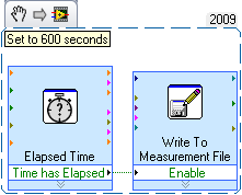
When you have an Express VI elapsed time set to 600 seconds (10 minutes). If every 600 seconds time out will pass a Boolean TRUE, which will allow to write the measurement file Express VI. Therefore, what iteration of the while loop, you would write some input comes in the signal input to write it into a file position.
There are other ways to do this as well, but it's pretty simple. I hope this helps!
Thanks for choosing National instruments.
Aaron P
National Instruments
Technical sales engineer
Maybe you are looking for
-
Portege R700 - Telstra and Dodo SIM cards disconnection
I have a new R700 and I am having trouble using my Telstra cards or Dodo SIM internally using the Toshiba Wireless Manager. Two of cards using the USB modems however if used internally during the connection work, it immediately fails and says "discon
-
Hi guys, I have a problem with my iPod Classic. A few years back that I dropped my iPod on the floor who killed the HD recently, I replaced the HD myself and it worked for about 3-4 days. While I was listening to music and play a game on it I realize
-
Mr President I joined the community vatsim (the international flight online network) for fsx. It's more realistic than fsx never giving live atc communication with atc controllers. That is why I joined it. After I signed up they asked two software do
-
I installed a multiwheel on my PC and it seems to be connected, but it will no longer work of Colin McCrae DIRT. Pls advise.
-
I don't like the useless hub so I can get my emails, text messages and BBM other than that?