Agilent ENA s3p file
I'm looking for something fairly simple to generate a file s3p for my Agilent E5071C Network Analyzer. I guess my greatest need is to find a way to get scanned data. At the moment I have just set up the 9 tracks (S11, S12, S13, S21, S22, S23, S31, S32, S33) and then configure my markers and take individual measures. There must be a way to collect a data table on a bandwidth of a trace. Anyone know how? Thanks in advance.
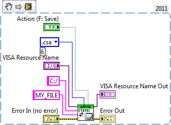
The problem has been resolved relatively easily on mine as follows:
Use the VISA Write block to send the following strings:
- : MMEMory
 torusNP:FORMat AUTO
 - : MMEMorytorusNP:TYPE3 P 1,2,3
- : MMEMorytorusNP
 ATA 'C:\filename.s3p '.
The Agilent ENA Series.lvlib:File transfer from storage Device.vi allows to recover the file from the Network Analyzer and store it in a local file.
Again, I have no problem to find a solution on my own (obviously), nor do I have problems with a lack of support or answer, however, I have a problem with the comment ironic and demeaning. Please keep to yourself if you do not have any positive suggestions for those seeking honest suggestions and help on this support forum. Thank you.
Tags: NI Hardware
Similar Questions
-
possible bug in Agilent ENA series LabVIEW Plug - and - Play (project-style) Instrument driver
think I found a bug in this driver and I wanted to get confirmation. (Here's the link to the driver page, to help locate the driver):
( http://sine.ni.com/apps/utf8/niid_web_display.download_page?p_id_guid=74D1F1D4EB5268E8E04400144FB7D2...)The VI in question is public > Action-status > configure > marker Configuration > Configure Marker.vi.
The question that I saw was that the marker was not be set to the frequency transmitted to the VI. (The parameter named 'Stimulus'.) I looked at the guide to the programmer for the Agilent 5071 B and decided that the format of the SCPI command string should probably:
%.;:Calc%ld:Mark%ld %s;
: CALC % ld: % ld MARK: X % lfThe ": X" had disappeared but seems necessary.
Can this be verified?
Thank you for taking the time to look at it.
-Joel
Snood1,
I took a glance at the driver and manual of the programmer. It seems to me that the driver behaves as described in the manual should. Configure the Marker.vi use the following string to format the command:
%.;:CALC%ld:MARK%ld %s;
:CALC%ld:MARK%ld:X %lf
Is that what you see too? Looks like that's what you added yourself. What was the previous text? This is the text that was there when I downloaded the driver. When it is interpreted, it looks like this
:CALC1:MARK1 OFF;
:CALC1:MARK1:X 0.000000
As described in the ENA series Programmer manual, the first turns of the line of the marker reads OFF (page 283). The second line sets the value of the marker 1 (page 295) stimulation.
Let me know if this looks OK to you.
Kind regards
-
Choose the Instrument of IDN? result (case of the chain)
I'm trying to find a way to read from several differently formatted instruments IDN? result (GPIB) in Labview and choose a case to control this specific instrument. I tried several channels different research/scans and nothing seems to work quite right. The method used in the attached vi comes of the NOR official initialize the driver for an E5071 Network Analyzer. but since it works only for Agilent ENA series VNA it does not account for other IDN? format. Two other analysers we are 8714ES and 8753.
Thank you
Jamie
(this file is ver. 2014 let me know if I need to convert for older)
It work?
See you soon,.
McDuff
-
Reentrancy in ansynchronously called live
Hi all
Recently, I developed an application that uses widely one communication GPIB Subvi, who writes a query and reads the responses of a single machine. To avoid collisions, I deliberately put this VI as not reentrant.
The Subvi is called by another VI, of course.
Now, please look at this situation: I have run several instances of the appellant in an asynchronous way? We'll respect the policy of non-reentrancy?
I have hard times debugging the monstrosity that I created and I think I'm on collisions here.
Please, share your ideas. Thank you.
EDIT: I would be grateful if someone would like to share also a method of verification instruments GPIB (namely Agilent ENA) is ready for the query. I would implement this mechanism just to be sure that the non-reentrancy is respected.
Dear McTom
Yes, when you call a non-reentrant VI anywhere in your code, even in calls asynchronous, only one copy will exist, so all calls to this function will have to wait their turn before the end of the call running.
If you need a more sophisticated approach, let me suggest your communication GPIB of migrating to another loop. You can create a queue to send requests to this loop and pass the reference of the queue all the asynchronous calls. This way, you have the possibility to monitor the State of the loop (number of items in the queue of the current item, status) as well as some manipulation of advanced queue (priority, hunting queue messages).
Kind regards:
-
extract data from record of an E5061B Analyzer
We have a document from third party showing a Panel before Labview with the plot of an Agilent E5061B Analyzer use. So we think that this is possible.
We have a parser to use Agilent E5061B. LabVIEW 2014 runs on win7 pc and using a USB GPIB interface. And her example .vi "Agilent ENA series gain trace.vi, Agilent ENA series interactive application.vi, acquired E5061B trace" we can get Labview to retrieve field data from the parser to use Agilent E5061B.
Dose anyone install Labview on Analyzer here?
Any ideas?
Thank you
Use the help > find instrument Drivers.
Orders for sustainable intensification of CROPS that uses the driver are all listed in your manual.
-
I've written in the past weeks I have been troubleshooting a LabVIEW 8.6 program to control our Agilent E5071C ENA. The program is designed for calibration of the Network Analyzer (measure calibration data and calculate the calibration factor) and store the State of the instrument after calibration. I used the AGENA (AGilent ENA) driver to write the program.
Here's my problem: the program works perfectly until the "Measure of calibration Data.vi" command is executed for the first through cal. In other words, that same VI appears six times before in the program (for short, open and load on a callus of two ports) and produces no error. When he tries to run the cal through, I can look at the ENA screen as he sweeps, but when scanning for the first through cal is complete, the device gives me a '-420: interview UNTERMINATED ' error, thus stopping the program.
I have been through the intestines of the individual VI wrote in the pilot of the AGENA and cannot identify any errors in the coding of GPIB. I have a cross reference of all the strings in the driver against what ENA programming manual. The error-420 me references to 6.3.2 IEEE488.2, someone has access to it?
Any help on this would be greatly appreciated.
Fern Adam
IDEAL Industries, Inc.
After a lot of hard work, I gave in and called the district sales manager for my region (Jorge Noguera, San Diego) to schedule a help session. Long story short, here's what is scheduled for:
"Calibration Data.vi measure" in a case that is selectable by the user for what standard to use solution (open, short, charge, through, isolation). This VI needs to be changed. After 'agena Write.vi' create another case structure before the agena "Wait For Complete.vi of operation." Inside of the place of the case structure a flat sequence with a 'Wait (ms)' command - set the command queue to 5000. In the structure of the case selector label refer to '3' (the same case that corresponds to the cal by standard) for the case with the wait command. Wire the switch case for the control of Word unsigned for the case of the pre-existing structure selector case (which sets the standard cal). Thus, when the cal standard value through, the structure cases wait is implemented after the agena write VI.
-
How to load the Calibration file Agilent Instruments LabView 2012
I'm using a vector Network Analyzer. Calibration is essential to give our creditbility of measurement results. In our case, we use Agilent instruments. Newer models allow certain calibration profiles be saved as States of calibration. These files are saved to the local hard disk of the unit and are loaded when needed.
What is the equivalent to set all the parameters of calibration in this .cal file in the Agilent with Labview 2012 instrument?
I downloaded the driver for my instrument and even ran the sample programs. It works fine but the calibration is set to the preset state that makes my whole system inaccurate.
It should look like this (assuming that it's a NAP you use):
-
the installation files that are necessary to control a 33210 agilent has via USB
Hello
I'm trying to control agilent 33210 via USB to a produce an arbitrary waveform using labview. The installation files I need? Obviously labview 86, ivi specific driver for 33210a, and? After you install labview 86, the program prompted me to install pack pilot devices, which I did, but he asked for disk 3 that does not exist in the package, I downloaded on ni.com.
BTW, is there a guide on where to go from there? I'm more c/matlab programming and graphic...
Thank you very much
Hi User2009,
Once you have installed LabVIEW and NI-VISA, you can do the rest of LabVIEW.
The simplest process is:
- Go to tools' Instrumentation' find instrument Driver and to use the finder driver tool to download and install the appropriate driver (I recommend getting the pilot LabVIEW Plug - and - Play project).
- "Once you have installed the driver open the example finder and navigate to hardware input and output" Drivers of instruments ' LabVIEW Plug and Play and find an appropriate example.
- Select your device and run the example to make the work of communication course.
- Use the example as a starting point and make any changes you need.
I got to have an Agilent 33120 at my office, so I recorded a quick video for you to the process described above. I use GPIB, but the process must be the same for USB.
-
Help with oscilloscope Agilent 54810 A data recording
I use an Agilent 54810 A oscilloscope with GPIB interface, I can't save the voltage (y-axis) and data(x axis) of the time together. I can only record time data.
could you please help, I would like to save the data to a text file.
I don't know why you say that you are only able to save the time data. What you save is the data. If you want to use scripture to measure file, create a waveform based on data type of Y and x increment that you receive from the wave function of reading. You simply use the wave function build for it (inside the loop).
With a constant True not wired to the GOLD from inside everything in fact point of termination of the loop makes no sense. Might as well not have while loop. With a single iteration, I understand not also the purpose of the exit of the auto-index in a 2D array.
-
Instant update for Agilent 34401 DMM in LabVIEW
Hello world
I am to acquire 4 wire measurement of resistance using Agilent 34401 DMM. I used the multipoint read VI file and wired a chart for measuring 1 d output data. I get the graph but after the number of samples required was taken by the DMM. The requirement is to plot the graph instantly and continuously, i.e. as soon as the DMM acquires readings.
How can I draw the graphs instantly?
Thank you
-Adityaadityasharma wrote:
Hello world
I am to acquire 4 wire measurement of resistance using Agilent 34401 DMM. I used the multipoint read VI file and wired a chart for measuring 1 d output data. I get the graph but after the number of samples required was taken by the DMM. The requirement is to plot the graph instantly and continuously, i.e. as soon as the DMM acquires readings.
How can I draw the graphs instantly?
Thank you
-AdityaDo not use the Multipoint reading. Just read a single sample. But reading inside a for loop. Then say you how many samples you take how many times you run your loop FOR. Put your terminal board inside the loop FOR and connect to the output of the reading.
-
control e363x of agilent power supplies series
I'm writing a vi where, after 30 seconds I want to change the output power of the power supply e363x agilent.
The communication is done via Rs232.
Initially I econfiguration tht to limits and voltage intial level then I created a sequence of images and otherwise I put a delay of 30000msec and then a trigger of software to modify the level of tension.
I repeated this sequence about four times.
When I run that the vi connected to my diet food .the first 30 seconds time-out is executed however the second time delay lasts only 10 dry and the last periods is performed properly.
However when I run the PGM without any connected instument I sent some smaple output form different frameworks and the delay time of 30 seconds was performed in all four times.
1. so I do not understand why in the real world scenario the second expected is not running or starts to run as soon as possible?
2.i got the trigger output example code in the driver. But I was wondering if I could just replace this part of the code with four others configure the voltage output with different levels?
I have attached the vi for your reference however if you do not have the drivers installed, you can refer to the image file showing the frame delay atypical and the handle of the pitcher.
Clarification in the problem will be highly appreciated.
First comment!
do not wait until the next multiple ms if you want to wait.
He expects indeed but the first call may end soon! Somewhere between 0 and max all the time!
Read carefully what it means and use the ms of simple waiting in your case!
-
Reading of data of Agilent 34401
I read the voltage measured on a 34401 Agilent using measurment single Point in a loop For (so that I can graph results in real time). The only problem I'm having is that when I try to write data to a file, it is not written on two columns (literation/time loop and voltage) as I thought it would be. Instead, it is written as a collection of information on each iteration of the loop (including the date, time and a bunch of values "Delta_X"). Someone knows how to write data to a file so that it simply display as two columns?
Thank you.
-
oscilloscope to Agilent 3000 series - no communication
Hello!
Recently, we bought an Agilent MSOX - 3014 (2000-3000 series) A oscilloscope.
PROBLEM: Does not WORK with LabVIEW.
DESCRIPTION: The scope has been connected via USB to a PC computer and has been successfully detected by the system and LabVIEW and installed in the system. OR MAX says that the device is connected and working properly but it doesn't.
After you run a sample VI (acquire waveform) comes with plug-ins (project style) driver, the scope is set back to the factory setting and after a while, the connection is cut and there is no effect (no waveform on the screen). After this very simple procedure, the scope is not responsible for the material side (no response to buttons, etc.). The complete communication history was captured with NI IO-TRACE and I attach the saved file.Tested system configurations
(tested on two different computers with the same result)
LabVIEW 2010 32-bit
LabVIEW 2011 32 and 64 bit
Win 7 Pro x 64 (English version)
VISA - most recentI'm looking forward for your help
THX!
MJ
-
Can not find the tourmalines usb gpib interface (agilent io suite) max
Hello
I try to use my USB-GPIB Interface of 63488 TAMS in LabView.
There is a manual for the use of the TAMS Interfaces in LabView. You must uninstall all Suite of IO with the exception of the CLCL-pieces. The problem is, this option is not given in the new versions of the suite that run under win7 (14.2 +). And according to driver download site, you need to install Suite 14.2 +. It is misleading. On my request for a manual for the use of a newer version of the suite I don't got no answer so far, so I'll try on own and with your help, I hope.
To do this, I have installed on my Win7 x 86 system:
-LabView 2009
NI-VISA 4.6
OR-488. 2 2.73
-Measurement & Automation Explorer 4.6.2
-Agilent IO Suite 15.5
-TAMS pilot 63488 v1.2
The driver of the TAMS works on my system. The Agilent connection Expert I see the interface and the device connected. And I can connect through this connection.
To use this interface in LabView, I activated the NI-VISA for Tulip passport, but I had no new device in MAX I tried to activate the Agilent GPIB cards for 488 programs in the Expert of the connection, but it was not the solution.
So I checked the DLL. The GPIB - 32.dll is replaced by Agilent, so cards Agilent must be enabled for 488 programs. But the info for the t6348832.dll says "TULIP DLL for the USB/GPIB T63488". If the 488 option can take effect, but why I have no effect on the activation of the passport for a Tulip? Any ideas?
Thank you for your help and support.
Michael
For someone who has this particular problem:
I have found a small workaround to solve this problem. For this you need a Suite of Agilent, which will uninstall VISA without CLCL (review of Agilent IO libraries M.01.01 should be the last). With a tool like 7Zip, you can unzip the single installation file to get the installation files. Now you must enable the compatibility mode for Windows XP on the installation application before you install the libraries. After that, you can proceed as described by TAMS:
http://tamsinc.com/HPIB/60488/support/NI-60488.htm
Best regards
Michael
-
Agilent 33250 has synchronized with DT9812
Hello everyone,
I'm trying to control two devices (Agilent 33250 A and card DAQ DT9812) synchronizedly using LabVIEW.
I need excite a transducer using an arbitrary waveform generated by 33250 A burst mode with its frequency swept KHz x to Y KHz with a given increment. Breakup of period and number of cycles should also be adjustable.
I am trying to send orders for the generator of signals via port GPIB using LabVIEW VIs.I have the necessary drivers. (Config Burst Modulation.VI under "ag33xxx.llb" and Agilent 33XXX series generate Arbitrary Waveform.vi under "examples" in the attached file) but I don't know how to combine these two.
I contacted the instrument without any problem and I can take any form of arbitrary wave I want. I can also put the generator in burst mode, but I have to be able to do in a single VI.
After that, I also need to synchronize the process such as the each time that the frequency of the waveform changes, data is acquired by the computer. I have the LV-LINK to control data acquisition card. I'd appreciate any help that gets at least started me off.Thanks in advance
Deniz
Maybe you are looking for
-
My old Thunderbird e-mail account has been with Time Warner, SC. RR.com. my new second account) is with AT & T, ATT.net. In my old account I could give a name to a list of multiple e-mail accounts, put the name of lists at the BBC: and send email to
-
viewing deferred image or loading?
This has probably been answered somewhere, but my search terms are not finding it, I have not only a lot of problems. I don't know yet that my logical technical description. I think that this only happened since a recent firefox update last week. I w
-
Satellite 5105-S501 keyboard problem
After that I replaced my 40 GB hard drive with a 100 GB hard drive (the old frozen drive), I had a lot of problems with my keyboard.When I type, I find that the letters 'i' with tab back until a strange moment, the letter 'u' can tab forward, other l
-
LaserJet p1505 for connection wireless printing
I have a Laserjet P1505 (not 1505n) a Net Gear N600 dual band Router router with USB port and printer. I tried to connect the printer USB cable to the USB port on the router and installed the printer on the laptop (a Windows Vista) I'm trying to save
-
I use Hotmail on a new Mac and don't know how to increase the font size for the display of my email. you use the zoom + is only one temp. Suggestions please.