Align the two graphs
I have two Cartesian graphs, one under the other, and I want to align their vertical axes. Currently, this happens that the axis each tick labels may have different widths.For anyone interested, I realized that you can set the "binding" left the two graphs have the same width and the diagrams themselves to have the same width and they will be aligned.
Tags: Flex
Similar Questions
-
Align the two signals and measure the Phase Shift
Hello
I do an experiment in which I use the NI USB-6221 DAQ card. The jury is able to make 250 k samples/second. I want to measure two voltages in a circuit and find the phase shift between them at frequencies between 1 and 10000. First I ouputted a wave sinusoidal frequency variable through the Commission and applied to a test circuit. Then I used the Board to measure the two tensions consecutively (thus reducing the maximum sampling frequency at 125 k). I used the signals align VI and measured the two phases and then calculates the phase shift (VI attached in Phase 1). It worked well for the test circuit I built in which the phase shift went way logarithmique.20 degrees ~84.5 degrees and then stabilized. At frequencies above 5 000 Hz phase shift must have remained constant, but it varies more or less 1 degree. When the phase shift is 84.5 degrees, present a degree of variability is not particularly explicit. When I asked my program on the circuit that I really wanted to measure, the phase shift went from-. 5 degrees up to about 1.2 degrees. The change in the values of phase shift at high frequencies (> 3000) was environ.2 degrees. Given the small phase shift, this variation is unacceptable. Now I tried to use a sequence to each blood individually (increase the maximum sampling frequency to 250 k) and then align the two signals and measure the phase of each shift. When I use align it and re - sample Express VI to realign the two signals, I get the message "error 20333 analysis: cannot align two waveforms with dt even if their samples are not clocked in phase." Is it possible to align two signals I describe here? I enclose the new VI as Phase 2
Matthew,
I think I have an idea for at least part of the problem.
I took your program data and deleted stuff DAQ. I have converted the Signal on the chart control and looked then what was going on with the signal analysis.
The output of the Waveforms.vi line has two waveforms, like the entry. However, arrays of Y in the two waveforms are empty! It does not generate an error. After some head scratching, reading the help files and try things out, that's what I think is happening: the time t0 two input signals are 1,031 seconds apart. Since the wavefoms contains 1,000 seconds of data, there is no overlap and may not align them.
I changed the t0 on two waveforms are the same, and it lines up. The number of items in the tables is reduced by one. Then I increased the t0 of 0.1 seconds on the first element. The output had both greater than the entry by dt t0 t0 and the size of the arrays was 224998. Reversing the t0 two elements shifts the phase in the opposite direction.
What that tells me, is that you can not reliably align two waveforms which do not overlap.
I suggest that you go to 2-channel data acquisition and that it accept the reduced sample rate. You won't get the resolution you want, but you should be able to tell if something important happens.
You may be able to improve the equivalent resolution by taking multiple steps with a slight phase shift. This is similar to the way that old oscilloscopes of sampling (analog) worked. Take a series of measures with the signal you are currently using. The make enough average to minimize changes due to noise. Then pass the phase of the signal of excitement to an amount that is smaller than the resolution of phase of sampling rate and repeat the measurements. Recall that I calculated that for a 5 kHz signal sampled at 125kHz, you get a sample every 14.4 degrees. If shift you the phase of 1 degree (to the point/mathematical simulation), you get a different set of samples for excitement. They are always separated by 14.4 degrees. Take another series of measures. Transfer phase another degree and repeat. As long as your sampling clocks are stable enough so that frequency does not drift significantly (and it shouldn't with your equipment), you should be able to get near resolution of what you need. The trade-off is that you need to perform more measurements and may need to keep track of the phase shifts between the various measures.
Lynn
-
Need to align the two radio buttons in one line
Hi all
In my BlackBerry Application, I have a part of the user interface where I need to align two radio buttons in one line.
I used the code to design the user interface, but the two radio buttons below are overlapping.
SerializableAttribute public class BBSettingsScreen extends form {}
Rbg RadioButtonGroup = new RadioButtonGroup();
RadioButtonLayout raButtonLayout = new RadioButtonLayout();
raButtonLayout.add (new RadioButtonField ("ONE", rbg, true, RadioButtonField.FIELD_RIGHT));
raButtonLayout.add (new RadioButtonField ("TWO", rbg, false, RadioButtonField.FIELD_LEFT));Add (raButtonLayout);
SerializableAttribute public class RadioButtonLayout extends Manager {}
public RadioButtonLayout() {}
Super(Manager.VERTICAL_SCROLL |) Manager.RIGHTMOST);
}protected void sublayout (int width, int height) {}
Field field;
get the total number of areas falling under this Manager of
int numberOfFields = getFieldCount();
int x = 0;
int y = 0;
for (int i = 0; i)< numberoffields;i++)="">
field = getField (i); get the field
setPositionChild(field,x,y); set the position of the fieldlayoutChild (field, width, height); Spread the field
x += 30;
}width = 70;
height = 20;setExtent (width, height);
}}
}
Please help on this...
Thank you & best regards
Chintada Ravikumar
Try this:
RadioButtonGroup rgb=new RadioButtonGroup(); HorizontalFieldManager hr1=new HorizontalFieldManager(FIELD_HCENTER); RadioButtonField radioOne=new RadioButtonField(" RadioOne",rgb,true) { protected void layout(int width, int height) { super.layout(75,30);//Width and height according to the button name; setExtent(75,30);//width and height according to the button name; } }; hr1.add(radioOne); RadioButtonField radioTwo=new RadioButtonField(" RadioTwo",rgb,false) { protected void layout(int width, int height) { super.layout(75,30);//Width and height according to the button name; setExtent(75,30);//Width and height according to the button name; } }; radioTwo.setPadding(0, 0, 0, 20); hr1.add(other); add(hr1); -
How to align the two side by side anchored objects in InDesign.
I put a Word document in my InDesign doc and there are a number of images. They came as embedded images. Some of them I want to appear side by side or in a grid of all kinds. I'm not too familiar with anchored objects. Is there an easy way to align the ups and downs (i.e. ensure that the images are of the same height as the other) so that when they are side by side, they're aligned? Whatever I do for them seems to move them a little bit, but they are not perfectly aligned. Because I can't pick them out and do a typical line up as I would with ordinary objects, I don't know what to do. Sorry if this is a stupid/easy question. Thank you very much!
- Right-click on the selection of an anchored object and choose anchored object > Options.
- In the anchored object Options dialog box, choose Customize from the Position menu and click OK.
- The subject will probably move when the dialog box closes, but because it is now a Custom anchored object, you can drag to reposition.
- Alignment of an object embedded custom to other objects cannot be done with the control panel features line up because the anchored objects select individually, but with benchmarks commented under tension, you should be able to logically position.
Note: you can of course always UN-anchor an object if you want. Simply select cut, press ESC to kill the active insertion point and paste.
-
Hello everyone!
I suspect that the answer to this question is, but I'm asking anyway.
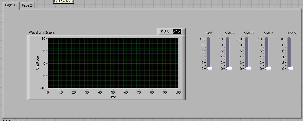
As you can see in this extremely simplified VI, I have a tab with two pages control. On page 1, I have a graph and a few controls. So, here's the question...
I need this exact configuration on page 2. What I have, it's like a mirror of each. If I insert data into the connection of graphs, I would like to show him
the two graphs. However... I want only one connector. I don't want a connector for each indicator/control. I want a connector for both graphics and
a connector for each pair of control. I could create a sub vi and use under panels, but I'm curious to know if this is possible.
I hesitate when I'm trying to explain something, then you can even do not understand what I'm asking.
Thank you!
Do you mean you want a subset of controls/indicators on all pages of your tab control (or at least will be displayed). One option is to move the controls in the tab control by using the arrows instead of drag and drop. I assemble outside of the tab control, group them all selected, and use the arrow keys to move in position on the control tab. You will see a shadow (slightly inconvenient) editing mode, which indicates that they are floating, but in Run mode, it seems normal.
Alternatively, I completely missed what you are shooting.
-
Tracing data from two locations on the block diagram on the same graph
Hello world
I'm trying to plot data from two distinct processes on a chart. These processes occur in the order.
I have developed several solutions, which none produce the result I want. What I want is for the data to trace in real time each process is running.
The two processes are functionally identical - one loop "for". With each iteration of these loops, data is produced and traced.
The data are plotted in real time, which means that each reference appears on the chart as soon as it is produced.
However, I am not able to get the second process data on the same graph in the same way.
The closest I got combines the graphic with a local variable. This allows the data for the two processes to draw in real time, but the second set of data replaces the first.
I have attached a very simple test VI showing my problem.
Any help with this would be greatly appreciated.
Thank you
You can do something like this. Is the second process just a continuation of the first? If so, it becomes even easier and you can just to keep construction of the table in the second loop.
-
Two indicators for the same graph.
How to connect the same indicators for the chart even if you have it in different tabs?
Looks like you want to use the same indicator in two different cases. It is not really possible, unless you want to use a local variable - which I would not recommend it. If you want something wire to the same flag from various cases, you need to place the flag outside the structure of the case, which makes a tunnel through the structure of the case.
In addition, it seems that you want to the same graph in two different tabs in a tab control. Why use different tabs if you want the same information? Maybe you could redesign your GUI?
But once again, as everyone said, share your code and it will be much easier for us to help :-)
-
Align the largest object of two objects
Hello
Let me explain with an example. Suppose I have two horizontal lines spaced 1 in. I have a square box with sides 2 inches wide. I would like to focus the housing vertically between the two horizontal lines. Is there a quick way to do this without grouping?
A way of centering the box is horizontal lines of group two in an object, and then align the box in the middle of the group object. But I would like to know if I can do it in fewer steps without grouping. If the box was smaller that 1 in., about I could place the box between the two lines, select all three objects (box + two lines), and distribute the portrait. Alas, the box is larger than the space between the two horizontal lines, so it does not work.
This is for CS4.
Thank you.
sPretzel,
I am afraid that grouping is the easiest and simplest. There are of course other ways (worst).
-
Alignment of two buttons in the Middle
Hi all
I created a rowLayout region and under that I created GO and CLEAR buttons. Now, I want it to appear in Center it horizontally.
I tried setting the Horizontal alignment as Center. But still don't get the button in the Center. Suggest an idea.
Thank you and best regards,
MyvizhiHi Myvizhi,
When you create a rowLayout you will find an alignment option: Horizontal alignment: Center and Vertical alignment: medium
Set the two property highlighted.There is also an option to set the width, you can try with 20%, 40% try with different values.
-Had
-
Can't align the widths of the two elements in my CSS
On this page
pictopoetry.co.uk/Category/Poem/
You can see there are two things I want to align, but they lack a pixel
 The two rules for the CSS are below.So my question is how do I raise these two elements for row cleanly?Thank youMartindiv #content h2 {-moz-border-radius-topleft : 0.4em ;-moz-border-radius-topright : 0.4em ;background : URL("images/bkgalphabr30.png") repeat scroll left top transparent ;color of the border : money - moz-use-text-color silver ;border-style : solid solid no ;width of the border : way to 1px 1px ;color : #666666 ;font size : 1.5em ;font : normal ;padding : 0 1em 0 0.625em ;width : 100% ;}div.post div.entry, div.entry div.post-chat - fifteen, div.entry, div.post-chat - three div.entry div.page {-moz-border-radius-bottomleft : 0.4em ;-moz-border-radius-bottomright : 0.4em ;background : URL("images/bkgalphawh85.png") repeat scroll left top transparent ;color of the border : -moz-use-text-silver silver ;border-right : solid silver 1px ;border-style : no solid solid ;width of the border : average of 1px 1px ;float : left ;the bottom margin : 1.25em ;padding : 0.75em 0.5em 1.2em ;width : 100% ;}
You are at the mercy of the percent sign. By setting the width of .entry as 100%, you lose the fine adjustment possibility which pixels gives you.
By changing the width of a 609px said (!), I was able to make them answer softly:
div.post div.entry, div.entry div.post-chat - fifteen, div.entry, div.post-chat - three div.entry div.page {/ * added div.post-chat - 15 * /}
background: url("images/bkgalphawh85.png") repeat scroll left top transparent;
border: 1px solid silver;
-webkit-border-bottom-right-radius: 0.4em;
-webkit-border-bottom-left-radius: 0.4em;
-moz-border-radius-bottomright: 0.4em;
-moz-border-radius-bottomleft: 0.4em;
border-bottom-right-radius: 0.4em;
border-bottom-left-radius: 0.4em;
border-top: none;
Padding: 0.75em 0.5em 1.2em.
margin-bottom: 1.25em;
Width: 609px;
float: left;
}
Beth
-
draw two graphs in the same XY graph
Hello
I want to save the graphs that are generated by a Vi in a programically file
How this can be done
Thanks in advance
Augustine
Hi, Augustine,.
Get the data in table form the XY graph using the property node and convert that chain of worksheet and then write to a text file.
The image attached can be useful for you.
Kind regards
Raja
-
align the cells with shared values
3.6.1 the numbers
I would like to compare two columns and align the cells, if they are equal. Ideally, I would like to include the adjacent cells in the second column in the alignment.
Example:
Run the formula (if possible) to format the following text:

As follows:

Hi cnickflight,
Easy to do by transferring the data to another table.

Table 1 contains the original data. I reduced the names of fruits to three letter codes to reduce type them, but this does not change the process.
Column A of table 2 contains a formula that copies the existing data in column A of table 1 and insert null strings when there is no data in the table 1.
The formula is entered in cell A2 and filled down.
Table 2::A2: = IF (ROW () −1 > COUNTA (table 1::A),"', SHIFT (table 1::$A$1,ROW()−1,0))))
Fill until the end of the column.
Columns B and C contain a VLOOKUP formula. The formula is the same in the two columns, with the exception of the number indicating which column of the table, the returned value must come. The version of 'testing' of the formula in B2 is shown. When filled to the bottom, this formula should copy the names of fruits where they are both on the table 1, in the line that they appear in column A, and display a triangle of error in the lines where there is no name in column B to the one in the column (and in the rows where column A is empty). The error message for each of them should be "VLOOKUP couldn't find the requested value."
Table 2::B2 (trial version): = VLOOKUP ($A, table 1: $b$ C, 1, FALSE)
(FALSE appears in the formula as 'exact match' editor)
If the behavior is as described, add IFERROR before VLOOKUP, and , "") after the closing parenthesis to match the 'final version'. " (See "why two versions? below.)
2::B2 (final version) of the table: SIERREUR = (VLOOKUP ($A, table 1: $b$ C,1, FALSE),' ')
2::C2 (final version) of the table: SIERREUR = (VLOOKUP ($A, table 1: $b$ C,2, FALSE),' ')
Fill both until the end of their respective columns. Results should now be as shown above.
Note: Why two versions?
Function SIERREUR is ideal for use as a trap for the error, but it acts on all errors, not only the one you plan to trap. Best practice is to add to this trap only if you are sure that the formula generates other error messages that awaits you and using in this case we know VLOOKUP, who has been charged with finding an "exact match" will throw an error when it does. Function SIERREUR catches this error and puts a string anywhere in the cell, making it appear empty.
Kind regards
Barry
-
Draw two graphs, a simple graph
Hello. This is my first time using the command and the simulation. I want to draw two graphs in one graph. It seems that I have to use together and to build tables functions but I don't know how to draw them. The points x and y (2) are only defined by a single set of points included in the defined table. The points x and y (1) are the results of another formula, but the two parcels would fit in the same location in a single chart. I hope that my question is understandable. I attach a portion of the model I want to be plotted.
Thank you
Hello
You can try something like that. Check the attached VI.
Kind regards
Amine31
(Give congratulations to good answers and Mark as a Solution If your problem is resolved
 )
) -
missing samples in the waveform graph
Hello world
When processing a file .wav into pieces, I noticed that there are missing samples on the waveform graph where two pieces must be met for the display. What could be the cause of this? Any help appreciated. Thank you!
Milan
Your method of reading in pieces in a for loop is create a table 1 d of waveforms with the tunnels of automatic indexation. It is as well as what you have the data appear in different plots. I don't know if that's what you want.
But if this is the case, the problem is that you get to the last point of the first plot, and the first point of the next parcel is a different value. Because they are two different plots that you do not get the line to join them, as you do between points that are part of the same plot.
-
Hello NOR community,
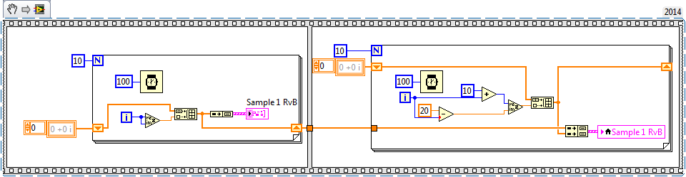
I'm new to LabView and was hoping someone might be able to help with a question I have. Currently, I use a data acquisition unit to sample external sine and I would like to change this signal by adding another signal that I could control using the front panel. Whenever I try just connect entry with something like the waveform sinusoidal vi and put a subtraction sign between them it doesn't work (I get an empty waveform graph). To work around this problem, I've resorted to a signal (via an analog output) and followed by reading the signal to data acquisition, and then finally I add the two together. It works this way, but he wastes two channels and I imagine that there is a better way. I enclose my VI, and I have marked the location of interest "where signals get subtracted ', which is currently displayed using two entries.
Thank you
Leo
You must ensure that your sampling frequency and number of samples is the same. It seems that your sample (with default values) rate is the same (1 kHz), but your number of samples is different (100 to 1000 the acquisition wave vs simulation).


Maybe you are looking for
-
Can satellite M70-159 - I replace the motherboard with another?
Hello!The model of the M70-159-card mother K000033840 can replace another motherboard with a number K000033860? Thank you.
-
Re: Satellite R630-13U and support for Win 7 32-bit professional
Hi guys,. I just bought a Satellite R630-13U pre-loaded with OEM Windows 7 Home 64 bit, but I had problems to launch our database application causes it does support 32 bit operating system. So, I intend to change the operating system to Windows 7 Pro
-
Whenever I press the blue # on the keyboard of laptop, it enters a 2 instead
you know the blue # on the portable keyboard although any time I press on these keys, such as k ithatt will enter a 2 instead please help * original title - keyboard help *.
-
I have windows 7 on drive C and D (doesn't), I want to formate D how do?
I have windows 7 on drive C and d., while that 7 in d drive does not work, I want to formate D how can that I do?
-
Can I request credit if I can't open a file under license?
I bought a file AI AdobeStock_54294982.ai think I'll be able to import my other graphics software, but without success! I tried to open it with various software, but nothing helped.Could I ask my license for this file to be removed and credited to my