analog digital 2-loop 2
LabVIEW 2013 SP 1
Windows 7 Pro
Acquisition of data OR PCIe-1433
Print custom, attached to the acquisition of data
Each individual signals disucssed has been tested and works.
Hi all
I have an application that makes a bunch of installation, when the user clicks on the go, running a main loop which does a number of things, save pictures, etc. and also periodically sets the digital output pins HI and LO.
This must be synchronized with the image recovery and storage.
It works well.
I have to add 2 analog input signals, also synchronized with the Digital out and capture video.
I simplified so only in the test application, I start the application, set up some preliminary stuff and when the user presses, run a main loop.
For now, I deleted the video component and components of data files.
The application of test fires a single digial outside (for example puff left) and start listening on a single Analog In (e.g., left mic).
When the left microphone reaches a threshold, it flags and stop listening.
When the time is up, exit (left puff), digital has LO.
If the threshold has not been reached when the digital timer is in place, he stops to listen then too.
It works fine (the first time).
However, the loop continues to run as it should. When to prune them next time comes around the same thing is supposed to happen again (left or right), the digital signal not to is not triggered and analog in is not started.
And this failure is true for all future iterations of the loop.
I threw in a counter to show me the LabVIEW registering the case statement, and this is as it should. But the signals are not generated.
If I go on the diagram and turn on the 'bulb' followed; everything works.
I get the digital output when I should, I get the analog.
When I turn off monitoring, it does not work after the first iteration.
I have attached the sample file.
Any thoughts are appreciated,
Jeff
Hi DMJeff,
If you turn on the running highlight and it works fine, then it does not work without it, this seems like a good hint that this has to do with the time. I check the functionality of timing and possibly define some probes in there to get values.
Tags: NI Software
Similar Questions
-
analog/digital using canon hv-20 can see video import widow but nothing saved iMovie10.1
analog/digital using canon hv-20 can see video in the import window but nothing saved in libraries after
As you use your HV 20 analog to the digital pass-through mode, this can help.
-
6143 - PCI or PCI-6133: simultaneous reading of analog, digital, and counter
Hello Board,
I want to use a PCI-6143 or 6133 to acquire permanently synchronized values ports analog, digital, and counter on the same device.
I use vb.net to build an application that reads the values of the device buffer and stores them in lists for later use.
By reading some other threads I discovered, that all the S series devices are able to use a source of material for the release of the digital ports.
Here are two among them? What meter ports, they suffer from the same problem?
Software trigger is no option because the sampling rate must be accurate.
Thanks in advance for the answers,
M.B.
Hi M.B.
6143 does not support Correlated DIO (i.e. clocked by the hardware), the 6133 (see-> digital I/o--> Timing). As a result, synchronized doing of entry works with the latter. Acquisition of meter in the buffer is available on both devices. The 6133 also authorizes analog and digital triggering.
To synchronize these tasks, you need to export a clock signal (sample clock HAVE for example) and take to the DIOs and counters for an acquisition in the buffer. An example for synchronization of AI and DI is given once you install the DAQmx driver in the
Please let me know if you need more specific information.
Kind regards
Peter
-
Tecra S3 Advanced Port Replicator III more: video output, analog & digital
I have a Tecra S3 in association with Advanced Port Replicator III.
I can't get the two graphics cards to work together.The analog and digital video output should work together.
It works on a Tecra S2, but not on the S3?
Does anyone have an answer?Hello
You want to use both outputs DVI and VGA on Advanced Port Replicator III graphics more simultaneously?
Advanced Port Replicator III more supports the use only if the computer system unit laptop itself also supports the simultaneous use of RGB & DVI.
So that would mean that the backs of Tecra S3 not supported this feature
-
Hello
I use a power supply (kepco BOP 100-4, if it helps) and control using a card PCI-6221. I am also able the current and voltage in the circuit of load using the same Board.
Feeding is a floating source, but took me to the Earth, so for measures to HAVE it, I use the differential mode. On the power supply of the entry and exit have the same pattern, so I was wondering if there was any risk of a loop of land due to the GND AO?
Thank you
scalpas:
I think that all the grounds (digital I, AO,) are bound to the Earth in the PC. If you have an ohmmeter, with PC and unplugged, look for continutiy between a GND pin on the acquisition of data and the metal casing of the PC part (case is usually connected to AC power grounding).
-AK2DM
-
Identification of analog/digital PWM
Hello
Lets say I'm measure some signal using an analog input (for digital pwm would better mabye?). It may or may not be a PWM waveform, could be 0V could be a tension continues (even just a little 100% PWM cycle). It could also be other things like a sine wave etc.
What should I do with this entry is to determine the following:
Is the waveform a PWM wave? And if it is a PWM what is the duty cycle?
I tried to look through the different screws to signal analysis, but has not been seen as a bit of luck to find something. Ideas or examples on how this would work?
Thank you.
Help > find examples
-
inputs and outputs analog digital usb 6009
I'm having a problem with my USB 6009 in labview programming. I try to read continuously from the analog inputs while having an event focused on digital output within the same program/vi. Basically, I need to taste all the time the analog inputs while having an event defined by the user (button control) to signal the digital inputs to turn on then after awhile. The event of digital output must be independent of the analog sampling system. I was throwing the "error already allocated resource" in most of the vi, I wrote to try to achieve. What is programmatically possible with usb 6009? I am at my wits end trying to do this and any help would be greatly appreciated (by myself and my boss). Thanks in advance for your answers.
RJ
-
Hello
I use a digital converter analog VI. I see that VI, all parameters except the sampling frequency. An ADC must always come with like 10KSPS sample rate, 1mech. Can you tell me how to control the sampling frequency of the ADC. I have attached snapshot of my code.
Thanks for the details.
-
Sync USB analog-digital 6008 in ANSI C
I need to read four analog channels and two digital channels of a USB-6008 simmultaneously more or less at a frequency of 2 Hz (time interval of 500ms). I use NIDAQmx and ANSI C on WinXP and end ++ 2010 Express. There are two problems in ANSI c:
(1) implementation of a software developer. The System32 timers are not reported to be precise below above 1 Hz, taking into account the vagaries of WinXP.
(2) realization of synchronization between the two types of input channels is not simple. Apparently, the code integrated with NIDAQmx (told-ReadDigChan) example is not intended for the 6008.
Someone maybe all example of C/C++ code that address one or both of the above challenges?
Thanks in advance for your time,
willemf
A more sophisticated device. the 6008 DIO cannot timed client software and is not supported and when to trigger or material.
-
Windows Media Center will not scan digital channels using a dual tuner (analog/digital)
I have an AverMedia Volar Max tuner which is analog and digital double Windows 7 Professional
Media Library 'sees' the tuner as an analog tuner and properly identifies all the analog channels, that I see on TV.
However, none of the digital channels are detected. I have not found a way to "force" a search using QAM256 or any other research of digital formats. Using the tuner, cable and connections the same BUT with a linux sotware (mythtv) all digital channels have been identified.
Is the problem because its analog and digital modes? How can I force Media Center to see the digital capacity of the tuner?Might have been a better place to look for information on the AverMedia Max Volar tuner AverMedia USA site.
If you had looked here to find the latest drivers or to read support information, you would have found:
The support of the AVerTV Hybrid Volar MAX QAM signals on Microsoft Windows Media Center? Currently, Microsoft Windows Media Center does not signal QAM. You will need to use our AVer Media Center in order to receive the QAM signal. Please download the application on our website programs:
-
Analog & digital audio scrubbing
Hello
I'm about to be a new user of CS5 Production Premium. New system certified on command (Z800). I was a demo of CS5 and spent some time browsing this forum etc. and that you can't find the answer I wanted. My question is:
During audio demo rub has commitments and the audio has a digital output of the sound (audio choppy resulting). I asked if it was possible to move the sound of rubbed analougue for a smooth rendition of the track of the timeline. The demonstrator was unaware if thiswas a feture in CS5.
Suffice it to say, for me, this restriction would mean a difficult edition as I oftem need to synchronize the classical music with say instument subtle sounds from different sources of the same event. Is it possible to scrubb analog audio and no digital output.
I'm pass after a long decision liquid form (Avid) as MC does not fit the Bill for me. So Adobe CS5 here I come back in a few weeks time. Yes - a new learning curve and perhaps a few other questions here.
In any case I hope that some of you wise owls will be able to let me know. I am based here in Shakespeare Land - Stratford - upon - Avon UK.
Thank you in advance.
Gavin.
But, soft! what light through browser there breaks? This is the answer, and JKL plays is the Sun.
(Sorry... of the...)
Gavin (and Craig),
You can get what you want by holding down the key "K" (pause) and alternately pressing 'J' (reverse) or 'L' (forward) audio playback in a way slow, analog, reel to reel. Instead of samples of individual time of segment, you'll get a slower and less acute audio playback that is continuous, compared to 'step' usual reading you get when you navigate with the arrows. You can also get the analog style reading using the shuttle slider in the Source or monitor program (which is just under the transport controls). When the JKL play is limited to a speed you can get variable reading, both slower and faster, using the slider of the shuttle. The wheel behaves like the movement of "picture by picture" arrow key, so it won't work for what you are after.
Hope that helps.
-
I need help with analog to digital VI
Hello
I am trying to create a 13-bit virtual adc
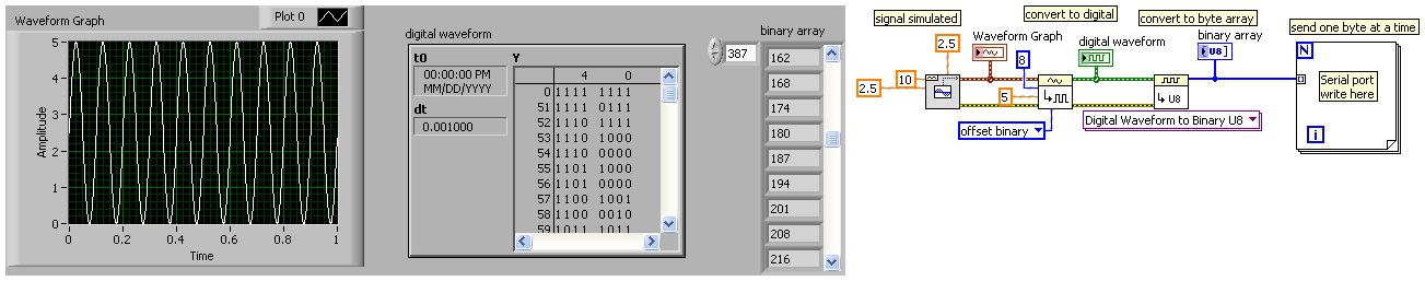
what I want to do is to use a simulated signal (e.g. sine, square, etc.). the sample at a rate of 8 khz frequency and send each digital sample serial port.
the thing is that I don't really know how to use the analog/digital VI, I know it converts an analog signal into a digital signal or a table, but I want to be able to use these digital data and not just watch it on a table
Sorry for my bad English and thanks in advance
Copy the code shows the conversion of a sine wave of digital data with a resolution of 8 bits, and then to convert digital data into a byte array. Send one byte at a time by the serial port.
-
I am writing the control software for a system that uses RF (clocked at 72 MHz) as a major component. None of our signals have harwdare filters and software I am sampling 100 samples at 1 k Hz. I have on average these samples and update every 250ms.
Using a language I can understand, can someone help me understand how RF may influence our signals and what options I have to filter this noise (harwdare and software). Or at least point me to a good resource.
Doug,
Here's the ME version of RF interference. The combination of transmitter/antenna radio creates electromagnetic waves in the space around the antenna. Think of dropping a stone in a pool of water. The wave analogy is reasonable for the basic understanding. A leaf floating on the pond goes up and down with the wave. If you put a float on the water and connect to the Mainland by a gearbox, you can extract energy from the waves.
In your DAQ system two things are necessary to produce interference. 1. the RF wave must be coupled to the system. 2. the RF energy must reach a point where a non-linear device converts the sine waves of very high frequency in a form which allows to measure the low frequency DAQ system. (2.a. There are a more complicated way interference can occur without a nonlinearity - subsampling).
How the coupling can occur? The wavelength of an electromagnetic signal in free space is the speed of light, divided by the frequency. For 72 MHz the wavelength is 4.17 m. A wavelength of antenna 1/4 long can couple to electromagnetic waves very effectively. Y at - it wire in your system about 1 meter long? USB cable? It is likely that you have some very nice antennas. If the voltage from one of these antennas reached about 0.5 V, it will be sufficient to cause the internal diode junctions in any device of semiconductor (such as amplifiers, analog/digital converters and multiplexers) of lead. This conduction is non-linear and produce a DC voltage out to the RF input. This tension Gets the sum (with unknown polarity) with the signals you want to measure, prodcuing errors.
What can you do about it? Disable the transmitter will not solve the problem, but because it is needed for other purposes, is not an option. The signals of interest being very low frequencies, it should be fairly easy to eliminate parasites. Three general principles apply. First is to eliminate the source, which has already been ruled out. However, check if the transmitter power can be reduced without compromising the performance of the RF System. Second is to reduce the coupling. If possible, keep the transmitting antenna as much as possible to the source of your slow signals and threads of connection to your data acquisition system. The orientation of the antenna and son can help too. There are too many combinations to try even give general guidelines on this without more information on the physical configuration of your system. Armor is a big part of the principle of coupling reduction and works well at 72 MHz. All the sons of your signal sources for the acquisition of data and data acquisition to the computer must be shielded. Should be based on the shields. Just make sure that you don't create ground loops in the process that can lead to other problems. Connect everything to a pattern with a 'star' grounded to System. The third principle is to reduce the signals interfere by filtering. I would try to put a ceramic capacitor of 100 nF for each signal line to the mass input on the DAQ hardware, keeping the capacitor leads as short as possible. If your sources of signals have a very high impedance or inductive, you might have an EE assess suitable filtering. The benefits of the capacitors are: cheap!, simple to install, will reduce RF interference over a wide bandwidth, require no development and are generally quite effective.
The problems are depending on the severity, it can be quite simple eliminate your interference or it might require a major overhaul of the entire system.
Lynn
ADDRA Consulting, LLC
-
Digital TV does not detect the analogue channels
new digital tv (26AV700A) captures all the available channels, analogue channels in particular. our previous analog tv picked up all the analogue channels when it is connected to the same antenna.
finished installing (Assistant) and auto scan which finds some of the similar, but not all.
the menu of configuration, channels submenu, lack two menu items specified in the manual of the TV - both refer to analog channels, IE
and It seems that some analog key functions are missing - is there a setting that turns the whole thing analog power?
Hello
I don t think you will get the right answer here because it is a forum for Toshiba portable computers/computers and all the stuff that has something to do with it.
If you have some problem with the TV I recommend you to contact your dealer in TV shop. They specialise in these issues and I hope they can help you with this.My friends also Toshiba TV and in the settings there is option where you can activate channel scan for channels analog, digital or both of them. There is also the option of quick analysis. Everything is described in s operating manuals.
-
G20-120: how to choose digital airborne signal to Qosmioplayer?
I have a G20-120 with analog/digital TV tuner.
I now wish to leave the DVB - T tuner to receive airborne television signals. (Try mine with analog signals only)
I can't find how? Any person who knows or who succeeded with that?MODIFIER
Hello
It would be very interesting to know what version of the Qosmio player you have.
I found this official document to support Toshiba:
http://support.toshiba-tro.de/KB0/TSB6101A90000R01.htmThere, I found information that 4.3 Qosmio player and older Version does not support the DVB - T signal.
The DVB - T signal can only be used in the Microsoft operating system
Maybe you are looking for
-
Help get rid of the changes and unwanted software.
Recently, someone in my house accessible a website called clipconverter.cc and recorded a few videos on our computer. I logged today to find a number of CRAZY to say "INSTALL ME" all over my desk, my changed Redirect 'Safe Finder' safari and 3 or 4 n
-
The letters are too thin to read
On my new Dell desktop with an E1910Hc monitor, there is very high definition, but the letters in many programs (including Word) are too small to read easily. In other words, the letters look as if they were written with a very fine tip pen, making l
-
CL Cap Svs Module has stopped working.
Start up - a window will appear - ' CL Cap Svs Module has stopped working - Windows will close the program and notify if a solution is available. " No not solution - Windows Vista Home Premium. Crashing in Flash Player custody - is that you connected
-
Oracle odbc dll-pointing wrong
I just moved to windows 7 from xp. I have a query that uses an ODBC driver for oracle. He seeks the msorcl32.dll in \windows\system32 and it isn't there anymore, but it is in \windows\sysWOW32\ how to change the path for the data sources work corr
-
What is the "best way" to see all the 'hooks' that affect the database?
Hi allI'm responsible for exporting all schemas using the data pump and then re - import the scehmas, yet once so we can reorganize the real table spaces.I know that this can be done using grid 12 c, but I'm not sure I want to use this feature for th