filterinmg RF analog signals
I am writing the control software for a system that uses RF (clocked at 72 MHz) as a major component. None of our signals have harwdare filters and software I am sampling 100 samples at 1 k Hz. I have on average these samples and update every 250ms.
Using a language I can understand, can someone help me understand how RF may influence our signals and what options I have to filter this noise (harwdare and software). Or at least point me to a good resource.
Doug,
Here's the ME version of RF interference. The combination of transmitter/antenna radio creates electromagnetic waves in the space around the antenna. Think of dropping a stone in a pool of water. The wave analogy is reasonable for the basic understanding. A leaf floating on the pond goes up and down with the wave. If you put a float on the water and connect to the Mainland by a gearbox, you can extract energy from the waves.
In your DAQ system two things are necessary to produce interference. 1. the RF wave must be coupled to the system. 2. the RF energy must reach a point where a non-linear device converts the sine waves of very high frequency in a form which allows to measure the low frequency DAQ system. (2.a. There are a more complicated way interference can occur without a nonlinearity - subsampling).
How the coupling can occur? The wavelength of an electromagnetic signal in free space is the speed of light, divided by the frequency. For 72 MHz the wavelength is 4.17 m. A wavelength of antenna 1/4 long can couple to electromagnetic waves very effectively. Y at - it wire in your system about 1 meter long? USB cable? It is likely that you have some very nice antennas. If the voltage from one of these antennas reached about 0.5 V, it will be sufficient to cause the internal diode junctions in any device of semiconductor (such as amplifiers, analog/digital converters and multiplexers) of lead. This conduction is non-linear and produce a DC voltage out to the RF input. This tension Gets the sum (with unknown polarity) with the signals you want to measure, prodcuing errors.
What can you do about it? Disable the transmitter will not solve the problem, but because it is needed for other purposes, is not an option. The signals of interest being very low frequencies, it should be fairly easy to eliminate parasites. Three general principles apply. First is to eliminate the source, which has already been ruled out. However, check if the transmitter power can be reduced without compromising the performance of the RF System. Second is to reduce the coupling. If possible, keep the transmitting antenna as much as possible to the source of your slow signals and threads of connection to your data acquisition system. The orientation of the antenna and son can help too. There are too many combinations to try even give general guidelines on this without more information on the physical configuration of your system. Armor is a big part of the principle of coupling reduction and works well at 72 MHz. All the sons of your signal sources for the acquisition of data and data acquisition to the computer must be shielded. Should be based on the shields. Just make sure that you don't create ground loops in the process that can lead to other problems. Connect everything to a pattern with a 'star' grounded to System. The third principle is to reduce the signals interfere by filtering. I would try to put a ceramic capacitor of 100 nF for each signal line to the mass input on the DAQ hardware, keeping the capacitor leads as short as possible. If your sources of signals have a very high impedance or inductive, you might have an EE assess suitable filtering. The benefits of the capacitors are: cheap!, simple to install, will reduce RF interference over a wide bandwidth, require no development and are generally quite effective.
The problems are depending on the severity, it can be quite simple eliminate your interference or it might require a major overhaul of the entire system.
Lynn
ADDRA Consulting, LLC
Tags: NI Hardware
Similar Questions
-
How to generate analog signals?
Hi all
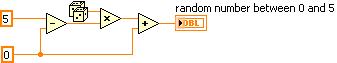
I'm trying to generate analog signals to simulate the position of the valve. I also want to simulate the position of the valve 0 - 5V (analog signal). I've implemented the numeric position of the valve by using the toggle switches, but I want to implement analog signals.
You can help.
Thank you
You can just use a random number generator.
Since you have no generator hardware signals of NOR, I'm not sure why you are posting to this Board. Generic questions of LabVIEW. Post to this Board.
-
Hi all
I'm still new to LabVIEW, but I played a little enough to create a simple analog signal generator. Product signals appear staircased when displayed on an oscilloscope, but are smooth, when I read the signals in an entry (as shown by the graph on the waveform) analog. How can I change my program settings so that I can see this staircased signal?
I run LabVIEW 2010 and use a data USB X Series multifunction acquisition.
Thank you
-Olivier
-
How to create an analog signal of a text or a binary file?
I'm trying out an analog signal of a file on a map of NOR-DAQ 6251 with labview 8.5. I found examples on the construction of a waveform, but I'm stuck at how read a text file and do a 1 d table to enter my amplitudes in the buildwaveform.vi and I can't find all the information on how to do it. Help or direction is appreciated.
Thank you
David
What if all you want in the file corresponds to the values of Y, then a text file with a value on each line can be read. Read from a usable spreadsheet file. It will return a 2D you can then use array index to get a column or if you select Transpose, the array returned by 1 d would be used.
If you want to create an example, use a 1-d array constant in a VI and pass it to the writing on a spreadsheet file.
-
How can I use my PXI-6115 meter analog signal trigger to generate pulses of frequency
I work on a PXI-6115 DAQ card and want to using the analog signal to trigger the counter it's generating frequency pulses. The manual says the analog trigger is supported, but I can't use an analog signal to trigger the start of work, in the test, I use the counter 0 to generate pulses and use the signal input port analog trigger PFI 0, can someone tell me what it is? My test VI. & error message appears in the attachment.
Best regards
If you read the error you can see digital triggers are the available trigger only when you use the output of the counter.
You can work around this by setting up a dummy analog input task which will trigger an internal digital triggering when he sees the right analog trigger.
See this thread for more details:
-
How to convert an analog signal into digital signal
Hello
How to convert an analog signal into digital signal, such that each sample of the analogue signal corresponding to 1.2V will be represented as '1' digital signal and other samples of the analog signal (which are not 1.2V) will be represented (converted) ' 0' in the digital signal.
And how to view the wavefroms or graphical indicators signals.
Thank you.
If you have 1000 samples and you want to convert to digital, you get 1000 digital values. Attached, that's what I mean.
-
Generation of the trigger (or TTL) analog signal
Hello world
Well I look at the droplet, riding on the vibrating bath. In this case I have to synchronize the device with the accelerometers.
Accelerometers are connected to the vibrating plate vibrating sinusoidal with frequency of 80 Hz. I am the acquisition of acceleration using NOR-DAQ USB 6212. A camera (Camera Link Basler, NI PCIe-1433) is used to acquire images of the vibrating plate. The frame rate of the camera is 20 Hz which controlled by external signal (TTL) or camera attributes.
I would like to generate a trigger of data acquisition (signal HAVE) to the camera at the first minimum acceleration in the attachment. I've also attached the file vi. Could if it you please let me know if is there anyway we can generate the trigger of the analog signal.
See you soon
NGO
Hello, NGO,
Can you post the update VI?
-
generation of digital, analog signals read snap SMU-6358
I have two SMU-6358 card and I want to send control signals to my camera and read the analog signals from the device with them.
For the digital control signals, I tried to set up a system where I specify the identifiers of the pins, bring them into arrays of strings - the respective waveforms would be collected in the tables too - and I transfer them to a VI of inputs/outputs multiples that puts digital waveforms for the cards output pins.
I developed this code here, but it doesn't seem to work. I can't understand how I can convert the string and form table wave to meet the requirements of the input/output VI or which another VI I could use to do the job. Or is there a smarter way to do it?
Thank you
Kriváň
Dear Kriváň
Please find attached the VI in LV 8.6 format. Also, I HIGHLY recommend to rearrange the front panel and which makes it neater, your code is very hard to read and not structured at all. I hope this helps!
-
How to compare an analog signal to another analog signal to see what signal has a higher value? I want to display the result on the façade with LED indicator.
This will make a simple comparison of A > B. If your code is more complicated then you must set up a system of producer-consumer. You can find examples of this in the supplied examples.
Here's a sample:
-
Output of different analog signals through 4 outputs
Hi all
Exit 4 different analog signals from the PCI 6711 map: I need help. I intend to use the waveform function from the palette of analog generation vi. My goal is to be able to enter the 4 necessary functions, it sampling information and then leaving four available analogue outputs available to the Board of Directors. I saw the code example for the output on multiple lines, but it doesn't seem like he is able to create unique waveforms through the exits, they are all the same waveform. I've attached what I thought work, but I can not get my number of rows in the data to match my number of rows in the task.
Specifically, choose instance polymorphic Analog-> multiple channels-> multiple samples-> 1 D wave.
Your current instance you chose is for just a single line.
-
Problem when the PWM signal combinning and analog signal TOGETHER!
Hello everyone,
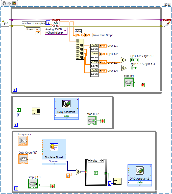
first I DAQmx 6212, and I need to run the water pump small (9V - 16V) that should be driven by a PWM signal; I also have a motor (5V - 13V) for a water supply which must be controlled by an analog signal and it has built in a force feedback potentiometer, I logged onto this potentiometer correction + 5V the DAQmx and used the output voltage of the third extremety as a value to diagnose to know the position of the engine.
My VI shows:
1 is a normal meter production to create my PWMout signal.
2 is an analog input, I use it as a PWMin to the LabVIEW to diagnose what is happenning in my pump water through the cycle and frequency.
3 is an entry of the third extremety of the analog potentiometer.
4 is an analog output that I used as power supply of the motor valve and I used an AC/DC amplifier for aplify signal the DAQmx and the motor road, between the two (3. 4.) I made a comeback with a few calculations, I had a P-controller to know the real position of the engine valve.
My problem:
When setting to 1. and 2. in the same VI only, I get an own PWM output with no problem.
also with 3. and 4. in the same VI only i can control the motor valve without any problem.
but when I put all these 4 set found in the attached VI, I have a problem as the engine valve turn continuously without stopping even if I change the position of the valve between 0 and 100%, I should mention that I see a PWM normal outside a signal on my oscilloscope, another thing to delete one of (1 or 2) and run the engine valve VI works fine without any problems.
so this my problem, if you can think of any solution please let me know.
Thanks in advance for your help.
Kind regards
Caliente
Here's your VI, slightly modified so the two analog inputs belong to the same task. This if only for purposes of illustration, I him have not tested. You will still need to do some debugging.
While changing your VI, I noticed another potential problem with your original configuration. You have configured the two tasks of AI for the same frequency, but read you 10000 samples of one of them and only 100 samples from the other (and throw it most of it). Data acquisition data are buffered, and if you read as fast as you acquire, the buffer fills eventually. If you read 10,000 samples of a channel, and the other channel acquires at the same rate, then when you read from the second channel you will get old stale data or an error full buffer.
-
Reading of analog signal using DAQPad-6016
I'm reading an analog signal using DAQPad-6016. An entry is on the ground, the other is Vdc. I can't operate at MAX and I'm confused becaue MAX alone gives me an option for differential reading, but the list of pins give enough information on how to connect in a different way. Is there a reference as well?
Hello, Bernadette.
This link should have what it takes to equip themselves properly: http://www.ni.com/gettingstarted/setuphardware/dataacquisition/analogvoltage.htm
After that you have put work in place, specifically see step 11 for check the connections of the device.
I hope this helps!
-
read the analog signal 0-10 volts of NI6123
I'm reading the analog signal of NI 6123. The range of the analog signal is 0 to 10 volts. This works well when the signal voltage is 0 to 5v (0 ~ 32767). But when the signal is 5 to 10 volts, the value read is always 32767. I also tried the different reading function: DAQmxReadBinaryI32, DAQmxReadBinaryU16, DAQmxReadBinaryU32. The value is identical to DAQmxReadBinaryI16. My OS is windows vista. Here's the part of my codes.
**************************************************************************************************************************************************************************
Create analog data tasks.
DAQmxErrChk (DAQmxCreateTask("",&datHandler));
DAQmxErrChk (DAQmxCreateAIVoltageChan(datHandler,"Dev1/ai0:7","",DAQmx_Val_Cfg_Default,-10,10,DAQmx_Val_Volts,NULL));)
DAQmxErrChk (DAQmxCfgSampClkTiming(datHandler,"",RATE,DAQmx_Val_Rising,DAQmx_Val_ContSamps,RATE*MAXLAS));
DAQmxErrChk (GetTerminalNameWithDevPrefix(datHandler,"ai/SampleClock",trigName));
Create counter tasks.
DAQmxErrChk (DAQmxCreateTask("",&ctrHandler));
DAQmxErrChk (DAQmxCreateCICountEdgesChan(ctrHandler,"Dev1/ctr1","",DAQmx_Val_Rising,0,DAQmx_Val_ExtControlled));
DAQmxErrChk (DAQmxCfgSampClkTiming(ctrHandler,trigName,RATE,DAQmx_Val_Rising,DAQmx_Val_ContSamps,RATE));
DAQmxErrChk (DAQmxRegisterEveryNSamplesEvent (datHandler, DAQmx_Val_Acquired_Into_Buffer, SPLEEN, 0, EveryNCallback, NULL));
DAQmxErrChk (DAQmxRegisterDoneEvent(datHandler,0,DoneCallback,));
Start the task.
DAQmxErrChk (DAQmxStartTask (ctrHandler));
DAQmxErrChk (DAQmxStartTask (datHandler));
In the call back function:
DAQmxErrChk (DAQmxReadBinaryI16 (datHandler, SPLEEN, 3.0, DAQmx_Val_GroupByChannel, data.laser, MISS * MAXLAS, & (data.dataRead), NULL));
DAQmxErrChk (DAQmxReadCounterU32 (ctrHandler, SPLEEN, 3.0, data.counter, SPLEEN, & (data.ctrRead), NULL));
write data to the file.
data.cfile.Write (data.counter, sizeof (int32) * RATE);
data.cfile.Write (data.laser, sizeof (int16) * RATE * MAXLAS);
**************************************************************************************************************************************************************************
Thanks in advance
To make sure that your device is working properly, I recommend first to test the entry in measurement and Automation Explorer (MAX) analog. You can test your device by right clicking on it in the configuration tree and selecting test panels. See if you acquired signal 0 - 10V as you expect. The next step would be to try one of the sample programs that perform a task of analog input. These examples can be found in the start menu > programs > National Instruments > NOR-DAQ > text based code supported. Try an example that does an analog input continues and double bed (instead of binary data not adjusted).
Your program looks good at first so I found nothing that stood out. However, one thing to check is if your function generator (or signal source) expects a 50 ohm or high impedance. This could cause reflections of the signal and cause the device to possibly read a voltage of half of the desired value.
-
How to use an analog signal to conditionally generate a TTL (or a square function) signal?
Hello world
I am using PCI-6229 and try to develop a code that can generate a TTL/place function signal from only one analog entry satisfies following conditions: 1. crossing a certain value (for example, 0 V); 2 slope edge of fall. The time delay between the point of passage and newly generated signal TTL/square will be essential to my measurement, and may not exceed 1 millisecond. Any suggestion on this subject? Thank you in advance!
You are using the measure called Excel add-in? That's what this forum is for. Otherwise, you should post to the multifunction DAQ card and speak the language you are using.
-
Hello world
I have a very simple problem that gives me a lot of trouble. I'm trying to run an engine on the analog output of a device of acquisition data NI USB-6211. I wrote a simple test code using the express VI and DAQ VI signal to control the motor. While the output graph displays the waveform that I need to control the stepper motor, the motor does not move. When I activate the program I can hear the motor buzzing, very faintly, that tells me that the program works and the engine is triggering correctly but there is not enough power for the engine to recharge the batteries. Given that my motor needs + / 3, 2V to trigger the so-called DAQ outputs hardware up to +/-10V (and) I don't think that the voltage is the problem. The only thing I can think is that the DAQ hardware is not really this output voltage, but I don't know of anyway to check.
If anyone has any ideas on how to solve my problem, it would be a great help.
I also downloaded my VI for reference.
Well, you check the voltage with a voltmeter.
Have you looked at the current requirements? You think there is not enough power and power is equal to the time of current tension. That said the spec 6211 is the maximum current output?
Maybe you are looking for
-
Re: Satellite P200-178 - how to replace the HARD drive?
Is it really possible to replace the HARD drive on this model? I have another satellite & which was 2 screws & pulling on one leg, job done. The P200 has an opening apparently get actually on the HARD drive but it gets you on the underside of the car
-
Pulsos fijado por tarjeta PCI 1426
Estoy utilizando una tarjeta PCI 1426 Trigger utilizando las functions led led componenete com CWIMAQ y introduciendo una Señal por el puerto secúndario esta tarjeta en modo EXT por el channel 0, ocaciones cuando estoy realizando en este procedure th
-
I lost all internet connections
original title; I lost all internet connections and all attempts to repair did not do what I do? I lost all internet connections. I tried all to solve the problem, but without success. Is it at a certain level of the code that I should bring in a p
-
Restore the backup after the clean install
I used windows backup on a hard drive, external, made a new installation on pc now want to restore my files but backup & restore will not do as it says that there has been no backup on this pc. How can I restore my backup files?
-
I wonder if I get a new processor and motherboard for this pc if it will affect anything either. I have a new case already that he's not going in but I'm decided to rebuild the pc everything except the hard drive so that I do not buy windows 7 again.