analog output ground loops
Hello
I use a power supply (kepco BOP 100-4, if it helps) and control using a card PCI-6221. I am also able the current and voltage in the circuit of load using the same Board.
Feeding is a floating source, but took me to the Earth, so for measures to HAVE it, I use the differential mode. On the power supply of the entry and exit have the same pattern, so I was wondering if there was any risk of a loop of land due to the GND AO?
Thank you
scalpas:
I think that all the grounds (digital I, AO,) are bound to the Earth in the PC. If you have an ohmmeter, with PC and unplugged, look for continutiy between a GND pin on the acquisition of data and the metal casing of the PC part (case is usually connected to AC power grounding).
-AK2DM
Tags: NI Hardware
Similar Questions
-
To input analog shutdown when the analog output is completed and synchronization
Hello
I'm trying to get my LabVIEW program to send analog output to a computer and read acceleration using the cDAQ-9184. Chassis output that I use is the NI 9263 and the chassis of entry is the NI 9234. I generate a signal of white noise using LabVIEW Express signal generator.
The first problem I have is the synchronization. I had an old VI that has begun to measure the acceleration just about a second after the entry has been given to the machine. I used the LabVIEW tutorial on how to sync the analog input and output, only to discover that it does not work with two different hunts. Then I found another tutorial that shows how to synchronize different frames between them.
The second problem is the cessation of the LabVIEW program. What I want to do is to generate the signal and then simultaneously send and read the input and output analog, respectively. It is because I don't want a phase difference or any shorter signal for a direct comparison. But as soon as the signal is sent to the machine, I want the entry to stop analog playback and then then the LabVIEW program must stop. I want to be able to choose any length of signal to be generated and stop as soon as the entire duration of the signal has been sent to the machine.
I tried 'DAQmx stop', "DAQmx Timer" and 'DAQmx's task made?' and none of them have worked for me. It is also my first time on a forum posting, so I hope I gave enough information. I enclose my VI as well. The VI shows I read an entry for the analog input voltage, but I am only using this to try to get to the work programme.
I'd appreciate any help I could get.
Thanks in advance
Peter
Hi Peter,.
I have some recommendations for you that I think you will get closer to your solution. First of all, I assumed you meant that you had 1 chassis (cDAQ-9184) who had two modules in it (NOR-9263 and NOR-9234). My next steps are based on this assumption, so if it's wrong, please let me know.
For your first question about the synchronization, the code you provided is very close to what you need. You need to do, however, implement architecture master/slave for startup tasks DAQmx functions. To do this, you can add another frame to the flat sequence structure and put the master start task (input voltage) after the start slave (output voltage) task.
To manage your second question and that the program ends at the point where you, the first step is to get rid of all the logic that you use with the local variable of length of time. Rather than use this logic, just wire the node "task performed?" of "is task performed?" operate to stop the loop. This will cause your loop to stop as soon as the signal is sent to the machine.
I have some other recommendations for you that will increase the performance of your program:
(1) rather than writing on file inside the last loop, you can use the DAQmx Configure Logging (PDM) .vi. You will place this VI between DAQmx Timing.vi and DAQmx Start Task.vi to the task of the analog input voltage.
(2) after the last while loop, you want to stop the task and analog outputs as well with another DAQmx stop Task.vi.
(3) rather than using a local variable for the entrance of displacement and wiring it in the DAQmx Write.vi, you can wire directly from the output waveform of the wave to build function node.
That should help you get started in the synchronization of these tasks.
-Alex C.
Technical sales engineer
National Instruments
-
poor performance analog output (error 200018)
Hello. I have a 6124 SMU Board with controller real time SMU-8102. the Council is speced to MECH 4 analog outputs. / s (one lane), but I have problems to operate at anything beyond about 500 kech. / s. I enclose my example below program. If I put the rate at 500 k, it works. If I put 1 m, it does not work and I get the error 200018 (DAC conversion attempted before Conversion data were available). I use the DMA transfer.
I also tried to increase or decrease the number of samples written by loop (between 50 and 300) and using a loop timed in labview real-time. That essentially gives the same result (sometimes I get error 200016 instead, "exceeding accuracy onboard device memory").
Because the controller is a dual core controller that do literally anything else (what I showed is the whole program, nothing else running), I don't know that I have some setting wrong software. I can't believe that this controller is unable to deal with this card. Does anyone have any suggestions on what I might try?
Version of LabVIEW is 2010 and DAQmx version is fairly recent.
Ok. I thought about it. Here's an interesting fact. At the rate of 1 MECH. / s, tries to write to 4096 samples each microseconds 4096 works perfectly well. But any attempt to write to 4095 samples fails! 4095 course is 2 ^ 12-1. It seems that DMA was running only transfers of 4 k at a time, so when he got 4095 samples, he was waiting for a sample more start the transfer, but at the time where he got this sample, it was too late. I changed DataXferReqCond property for "almost complete." Now, I can write about 150 samples at a time instead of 4096. Greatly improved!
Moreover, it would be really good to put in the text of the error message for the error 200018 so that others live several days tearing their hair like I did...
Thanks for the help
Daniel
-
Redeclenchables/continuous to a custom waveform analog output?
Hello
I try regular output an analog signal using the box USB-6211 and Labview2009. I looked at various examples of waveform, including the retriggerableAO.vi example, but I can't seem to understand how to send a 'waveform' custom stamp (terminology is perhaps the question). In all the examples (including waveformbuffer), I ran across the single waveform, the options are sine, square, etc. Previously, I posted on this forum looking for hardware suggestions (link here) and explained what I try to do and got the big help. To sum up, I would like to read a 'waveform' from a text file, send it to the usb-6211 buffer and then continue to an analog channel. At the same time, I'll use the beginning of the analog task to trigger a digital signal once per cycle as well.
I got in what concerns the establishment of the waveform, but am stuck to figure out how to get into the buffer and setting the frequency, etc.
Thank you
Gabe
Hi Gabe,
Dennis is correct that it will take some room to modify the existing screws to fit your need. As he says, the Con Gen tension Wfm - Int Regeneration.vi Clk - no example provided with LabVIEW. In the example, it can be shown that there is a custom VI used to explain the problems that arise when a waveform of a given frequency to a frequency of sampling and outputs analog specified.
With all that said, it seems you want to read from an existing waveform file that you created and this waveform to an AO output channel. There are a few things that will be needed to know before proceeding:
-What is the waveform as you try to output (5000 samples, 10 k, 100 k, etc.)?
-What pieces of the size of the wave you want output (100 samples at a time, etc.)?
-you want to again and again, or simply run through once the waveform looping?
Assuming that you already have the waveform and will only step by step, here's what I would like:
-break the large waveform into smaller pieces of waveform of standard size
-import the waveforms in LabVIEW and create an array of waveforms
-bring the waveform in the example Dennis mentioned previously with automatic indexing enabled on the tunnel
-Remove the generator of wave functions existing the while loop
-wire your indexed table of waveform for the data of the VI DAQmx of analog output terminal
It is possible that you will have to play with the settings of your waveform and timing of your VI, but this should be a good starting point. Please let me know if something is not clear or if I have misunderstood your original message. Have a beautiful reast of the day.
Best,
-
Read analog output channel value internally
According to this you can read the values of analog output of return without having to physically connect the wires.
By using the technique described in the example given (DAQmx_Read_Output_Internal_Channels.vi) I'm reading a current area of OCCUPANCY on my compactDAQ cDAQ-9174 with a module of analog output current OR-9265.
The output channel is created in MAX and my vi can write values to him without problems
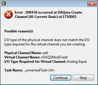
But when I try to create an analog input channel to read the output, an error occurs.
What I am doing wrong?
This is not supported by my hardware?
Or is the example given in the above incorrect link?
The example is 10 years old. Maybe, it does not work in LV2013.
Hi Jocker,
The link was not attached to your message, but I guess that's it: http://digital.ni.com/public.nsf/allkb/CB86B3B174763C3E86256FFD007A2511 as there the example of vi you mention.
The error you are getting is due to the use of the channel for analog output and trying to configure the task as a task of entry. You must use _aoX_vs_aognd as the channel of the task rather than on the output channel. This compares to the ground for the analog output values.
The NI 9265 is not on the list of the C Series modules that have internal channels:
So I guess that the module is not able to compare its output to ground. He would appear in the dropdown of the channel names if available.
Pete
Applications Engineer OR
-
Pressure sensor ground loop problem
Hello
I have an interesting problem, I hope someone can help me with.
I'm measuring pressure with a pressure sensor. We see a lot of noise with the measure, and I believe that we have a ground loop. I have checked the noise is 60 Hz. What is interesting is that the case of the pressure sensor is connected to the Earth. When we put on the sensor of metal pressure in the booth, we see the noise. When disconnect us the stand noise pressure sensor disappears. The stand is connected to the Earth. I'm feeding the sensor with a 24V power supply which is also connected to the Earth. I think that this is the ground loop.
My problem is that the 24V power supply should be grounded for safety and the I cannot isolate the ground pressure sensor.
I attached how I got the system wired. How to connect up to my analog input module pressure sensor OR 9215 to break the ground loop?
Thank you
Dan
Ahhhh Yes,
I have solved this problem. It is a ground loop. I had the field related to 2 places.
We have removed one of the references on the ground and poof everything worked fine.
One of the problems I've found is a reference of external power supplies and others do not. If you provide an additional reference to the Earth... Ground loop!
Ground loops can be mean terrible things. According to my experience, they are the number one electric goofiness and the noise causes.
I have compiled some resources on my website to help people
http://www.autosofttech.NET/resources
The best is field wiring and considerations of noise for analog signals
If you want the final word on the subject see this book
Techniques of reduction of noise in electronic systems
Hope that helps!
-
I searched through all the discussions and I know it's a very simple question... but couldn't find an answer...
All I want is a simple file of vi that has an output analog signal giving 5v to Xseconds, then to Yseconds 0v and keeps cycling constantly.
I have a BNC-2110 + PCI MIO 16th-4 runnign 9 of LabView
Thank you!!
Are you trying to do through LabVIEW SignalExpress (it is a SignalExpress forum, use the forum LabVIEW for a faster response to questions of LabVIEW)?
If you use SignalExpress, use the create Analog Signal step to create a square with the desired characteristics wave, then use DAQmx output stage in the repeat mode to generate the signal continuously.
If using LabVIEW, use instead Waveform.vi to generate the desired waveform, and then use the DAQ Assistant to create output to loop through this signal.
You can try SignalExpress to configure your settings, and then generate the code in LabVIEW if you want to use LabVIEW but want assistance in the drafting of the code.
If you need more information, let us know.
-
Strange analog output of USB-6211
I just got USB-6211 to replace USB-6001 to set the clock to external sampling on analog output for LED lighting control. The part of external clock example works fine, but the analog output voltage is strange. To do self-monitoring, I connected control pin LED to AO0 & AI0 of surveillance in the NI MAX test panel and LED control on the ground at AO - GND & GND HAVE since I have both USB-6001 and USB-6211, I conducted tests on two of them with the same setting of wire. When I generate sine wave - 5V to 5V to AO0 (from NI MAX test panel), USB-6001 can monitor the same signal AI0, but watch USB-6211 - 3, 4V to 3.4V voltage truncated. I did the test separately (wiring one device at a time), so there is no interference between the two devices. USB-6211 past self-calibration and self-monitoring. Also, I did reset devices. I don't know why they would behave differently with the same configuration, and I hope that someone could help with this question. Thank you.
Hi skuo1008,
The USB-6001 can support + / 5 output current my from terminals to analog output, while the USB-6211 box can provide only +/-2 my current output. It is likely that the load impedance is too low, causing the 6211 to hit its current compliance and thus cut the tension. If you try to exchange your load with a resistance of at least 5 v/.002A = 2500 Ohms, you should be able to see the full +/-5V sine wave. I suspect that your DUT has a words 3.4V/.002A = 1700 Ohms impedance. You could use a device with higher output current or use a more current source buffer circuit. If you do not need a bipolar output, you might also consider using digital lines to control the LEDs.
Kind regards
-
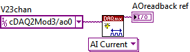
Bipolar analog output timed sample clock Glitch on zero
With the help of a card PCI-6221, calling in the DAQmx 8.6 with a stand-alone C application DLL.
I create and fill a buffer as follows:
volts1 float64 [2048];
for (int x = 0; x)< 2048;="" x++)="">
volts1 [x] = (-0.320) + (x * (0.640 / 2048));
}
My task is created and began as follows:
TaskHandle t;
DAQmxCreateTask ("WaveTask", &t);)
DAQmxCreateAOVoltageChan (t, "PCI-6221/ao0", NULL,-5, 5, DAQmx_Val_Volts, NULL);
DAQmxCfgSampClkTiming (t, NULL, 30000, DAQmx_Val_Rising, DAQmx_Val_FiniteSamps, 2048);
DAQmxWriteAnalogF64 (t, 2048, false,-1, DAQmx_Val_GroupByScanNumber, volts1, NULL, NULL);
DAQmxStartTask (t);
DAQmxWaitUntilTaskDone (t,-1);
DAQmxStopTask (t);
DAQmxClearTask (t);
The foregoing, less creating and by disabling the task runs in an infinite loop. It generates a very good approximation of a rising wave of saw (see complete.png).
Unfortunately, when you zoom in on the time axis, a glitch becomes apparent to the point where the wave crosses zero (see glitch.png). The glitch, as shown, is about 80 mV in amplitude and 2.5 U.S. (microseconds) in duration.
It is very short, but could be the source of trouble. Is there something that can be done programmatically to fix it, or makes it look like a hardware problem?
Thank you very much!
~ Brian
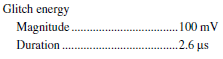
If you see the Specifications for the PCI-6221, you will see that there is a specification on page 3 of the energy of glitch on the analog output of this Committee. It is a result of the CAD on the tray and is not something that can be corrected in software. The specification is:
So what you see is under the specification, so your advice is really better than the spec run.
Hope that clarifies,
-
Using of FPGA VHDL IP and analog output
I use a system with Labview 2014 PXI. I've got Labview FPGA to program and run the card PXI-7854R.
I have the VHDL Code I want to use to control an analog output of the card. I use the IP integration node for this now but I also tried it making the process CLIP and still have not been successful. The problem that arises is that the IP integration node must be in a timed loop, while the analog output indicates that it cannot be put in a timed loop. Is there a way to provide an output of VHDL analog outputs of the card?
I tried to embed a loop timed within a while loop, but it still does not work.
I can't download the VI due to the policy of the company, but suppose I'm generating a sine wave in my VHDL code which must lead to the analog output of the card (the actual wave is company owner information but it is generated by a glance to the top of the table as a sine wave VHDL would be).
In an attempt to work the problem I retried import CLIP of the HDL code in a new project in Labview and VI. I'm still not sure about why it did not work with each other when I tried it.
For anyone who seeks to solve this problem:
I basically used this tutorial for the process CLIP: http://www.ni.com/tutorial/7444/en/
It also explains the differences between the CLAMP and the IP integration node.
-
Simple examples of analog output USB-6343
I've tried passing by 'find' examples and does not know how to find what I want.
I'm doing a simple analog output on a USB-6343. Examples of waveforms say they work with the USB-6343, but I really don't want a waveform, just analog of output does not exceed 10 Hz speed of renewal. Some of the more simple examples show that they work with the pcie-6343 but do not list USB-6343.
I worked with USB-6009 in the past, but when I try to use an analog output task that uses 1 sample on request, I get the error "not buffered operations clocked by the hardware are not supported for device and channel type.» Set the size of greater than 0 buffer, do not set up the timing of the sample clock or the value Type of sample On Demand time"
I tried samples N, 100 samples to write to 10 Hz - the same error. Samples of continuous - same error. 1-sample - timed HW - same error.
There is a series of examples of I/O for the X series? Is it possible to search the device examples rather than go through all the examples and by checking the list of devices individually?
Is 'size of the buffer' the 'writing samples"in MAX?
After contacting the support I was provided with the names of the more simple examples for analog i/o:
Analog output-Gen power Update.vi
Analog Input-Acq & chart voltage-Int Clk.vi
They are found in the getting started screen of
Click 'Find examples' near the lower right corner
Filter the results to material by clicking on the menu drop down for the material in the lower left corner and selecting USB-6343 (only connected equipment will be displayed)
Don't forget to check the box "limit results to material" below.
In the center pane, double-click 'Material Input and Output'
Double-click DAQmx
Path for the analog input - double-click Acq & chart analog measures - double click on tension - tension-Int Clk.vi
Double click on analog generation - double click on Power - Gen Update.vi of analog channel output voltage
The examples are for the single data point. Samples and exit multiples are produced by putting the writing or reading VI inside a loop. The beginning and the clear functions should be out of the loop.
Additional information, I need technical support was how material-filter results and identification of more simple examples which were not obvious from the examples of names.
-
Strange problem with analog output PCI 6251 and BNC-2110
I'm controlling current source of third parties using the connectors of analog output on my card PCI 6251 and BNC-2110.
The current source needs an input signal of 0.1V. I tested it using a battery, the potentiometer and the voltmeter, and by manually adjusting the voltage of power current works - current output with control voltage scales according to the specifications and is relatively stable.
The data acquisition card works too - when I connect a voltmeter to the AO0 AO1, the measured voltage corresponds to the target with great precision value.
But when I connect the current source of third AO0 AO1 data acquisition card, the measured output voltage drops and fluctuates. This applies to both channels of the AO.
I wonder what is the problem here. I suspect it could be a matter of the grounding - the current analog control of the source is an entry with two floating terminals differential. I tried to return the switches FS/GS on the BNC-2110, but that makes no difference.
Anyone knows similar behavior? Does anyone have any suggestions?
-
How to write constantly to analog output and read from analog inputs
Hi all -
I had a question about writing continuously to analog output reading simultaneously an analog input.
It's my first time to post a message to the community, so please let me know if I made mistakes.
I use Labview 2011 with a NEITHER-DAQ USB 6215.
I'm looking to generate a waveform and write it continuously in an analog output. It is then connected to an entry on the acquisition of data, where I am trying to sample the analog signal. (I realize, there is a system of trivial, but I'm hoping to build on it once I have run).
The task of reading from the analog input works fine, as I tested it in several other cases. I have a problem writing to the analog output.
For this task, I tried to follow the "Gen Cont Wfm Clck Int' VI to generate the wave form and start the task. I then try to write to the output of the analog timed loop. However, it does not seem to transmit a signal and doesn't give me any errors.
I have attached the VI but also a screenshot.
Please let me know if anyone has any ideas. I would really appreciate the help!
Thank you
Peter Borgstrom
We will review your tasks one at a time. First of all, the task of generation/Analog output Waveform. Generate you a waveform (I'm unsure of your VI if it is a fixed waveform or not) and send it to a defined output function to produce a waveform continuously, using N-channel and samples of N (where you set not these previously). You should not put this inside has timed loop, as the DAQ hardware has its own clock - if you simply put it in a while loop (with a stop to break out of the loop), the loop will call the function for the first points of N, wait until all N have been taken out, then call it again to another N points (up to what you press Stop).
Now, suppose that you have the output connected to a load voltage (say a decent resistance). You can wire the input terminals of your A/D converter through the same load and set up a similar analog input loop, running in parallel (i.e. in its own independent of the OD loop, while loop). You pourriez start together (with, say, a merged error since the initialization code line loops HAVE and AO become lines of error in "loops of sampling" described above), but you might want to delay loop (a little) the AI so that the OD has a chance to set the voltage before the bed.
I hope this helps.
BS
-
Analog output on USB6008 in C ANSI does not work
I tried to program the analog output on a device of USB6008 under MSVC ++ 6.0 with the latest NOR-DAQ 8.8.
The lines of the example of the ANSI C program ' MultVoltUpdates - IntClk.c ' work very well with a device emulator, but not as soon as I try to access the real device of USB6008.
/*********************************************/
DAQmx Configure Code
/*********************************************/
DAQmxErrChk (DAQmxCreateTask("",&taskHandle));
DAQmxErrChk (DAQmxCreateAOVoltageChan(taskHandle,"Dev2/ao0","",-10.0,10.0,DAQmx_Val_Volts,NULL));
DAQmxErrChk (DAQmxCfgSampClkTiming(taskHandle,"",1000.0,DAQmx_Val_Rising,DAQmx_Val_FiniteSamps,4000));During the call to the last line concerning the synchronization setup, an error occurs:
________________________________________________________
DAQmx error: measurements: request the value is not supported for this pro value
Property.
Property: DAQmx_SampTimingType
You asked: DAQmx_Val_SampClk
You can select: DAQmx_Val_OnDemandTask name: _unnamedTask<0>
State code:-200077
________________________________________________________
Is there a work around?
Finally, I want to set unique values for the analog output voltage in a loop.
In commenting on the "DAQmxCfgSampClkTiming" call, no voltage is defined in a "DAQmxWriteAnalogF64" call to handle this task.
Thanks for the tips!
'DAQmx_Val_OnDemand' is not a valid option for "DAQmxCfgSampClkTiming...." and leads to errors of execution, if I put it anyway.
As an alternative, I tried in the meantime:
DAQmxErrChk (DAQmxCreateTask("",&AO_V_taskHandle));
DAQmxErrChk (DAQmxCreateAOVoltageChan (AO_V_taskHandle, dev + ao0 "",""-"))
0.0,5.0,DAQmx_Val_Volts,null));DAQmxErrChk (DAQmxSetSampTimingType (AO_V_taskHandle, DAQmx_Val_OnDemand));
DAQmxErrChk (DAQmxStartTask (AO_V_taskHandle));
DAQmxErrChk (DAQmxWriteAnalogF64 (AO_V_taskHandle, 1, 0, 1.0,-))
DAQmx_Val_GroupByChannel & data_v_out, & writing, NULL));
(data_v_out = 2. ;--> back: written = 1) not--> no measurable output voltageDAQmxErrChk (DAQmxStopTask (AO_V_taskHandle));
--> still no measurable output voltage
Any other idea?
-
Decent analog output of my Qosmio F20-154
I use my Qosmio as a Microsoft Media Center with my TV connected via VGA output. It gives me a pretty good image.
However, my TV does not support most of the modes of zoom for VGA; or it does for DVI or HDMI.
So I tried the image output via S-Video - which produces a shitty and unacceptable photo.
Unfortunately, Qosmio has no TV output, so I can't try it.
So, does anyone know of a piece of hardware that can be used to make the Qosmio to produce a decent analog output, such as TV-Out (antenna) or Composite?
Thanks in advance,
BrianAs far as I know you have only two options to send the video signal.
Qosmio F20 supports viga video and s-video ports.
So either you will use the video VGA (15-pin) port or output video super TV (S-Video) 4pol mini to connect the TV to the laptop...I have connected my laptop to the TV also using the s-video port and the photo quality is OK.
Please check you s-video cable and if possible test another in addition, I would recommend check some settings on the TV and s-video option
Maybe you are looking for
-
Command line to install a safety device
Is there one was to install security via command line?Example: ActivClient (acpkcs211.dll) in order to allow the CAC/PKI authentication. Normally scrolls the Options - tab - certificates - safety in the graphical interface of advanced devices. Thanks
-
Satellite U50D-A - need wireless network adapter driver
Hello I have a Qualcomm Atheros AR956x wireless network adapterstatus "this device cannot start (code 10)" exclamation mark = in side of the yellow triangleso no wirelessOK EthernetImpossible to update via MS suspect this could cause problem in the f
-
Need me a SIM card for iPad mini 2
IM thinking about buying a mini iPad 2. But not sure if I need a SIM card. Anyone know?
-
Firewall settings Windows to ensure foreigners on the network cannot access the files on the PC
Hello It is about the security for files on a PC for example, the confidentiality of stored data. We define the firewall Windows to ensure that the files and data on the host PC are not accessible by users on the network. (LAN or Internet). Can we ge
-
Please help trying to change, connect for windows 10 summer to him now for three weeks has tried most of the things but nothing works very frustrated Thank you fred