Analog input base changes during digital output in parallel
Hi all
We use a USB DAQ 6008 to run a simple system. AI6 is connected to a motion sensor; digital outputs control a pump. We noticed that if we read AI6 without performiong of additional tasks, the baseline is ~0.17V and when movement is detected it comes down to 0.13V. However, if we read AI6 while performing outputs digital at the same time, the base line comes down to ~0.14V and when activated he descends to ~0.1V, i.e. the line base modified by 0.03. We do something wrong or is this expected behavior?
Thank you
Danielle
Danielle,
You may have a ground loop. If the current of the pump or even digital control for the pump through the Earth wire similarly that the signal of the motion sensor, the voltage drop in the common driver because of the current pump could cause an effect like you report.
Lynn
Tags: NI Hardware
Similar Questions
-
MULTIFUNCTION CARD analog input 4, 4 meters, 16 outputs analog
Hello
I am looking for a card of this product with the following features data acquisition,
- At least 4 meters
- At least 4 analog inputs
- At least 16 analog outputs
- PCI or PCIe or USB
Can someone give me an idea on the map OR equivalent specifications.
What will be the effect on the acquisition of data if I use two differernt cards? for example if you meter, analog output on a single card and entered only analog on the other card. Be it the questions of time between two cards over the selection of software such as LabView? especially when all the dry milli is very important for you.
Kind regards
WAQAR
You might want to watch a cDAQ chassis.
1. all the new cDAQ chassis have 4 counters on the backplane. They are accessible through any module "parallel" (essentially no matter what digital IO module with 8 lines or less, 9401 or 9402 are fairly standard according to the desired connector type).
2. There are a variety of analog input modules available for compact data acquisition - you can select based on your application (sampling frequency, precision, conditioning, etc.).
3. for the 16 analog outputs, you probably want to use a 9264.
4. the 9174 or 9178 use USB and have 4 and 8 slots for modules respsectively.
Best regards
-
Synchronize the clocks of 2 PCI cards for analog inputs with e/s digital reference
I'm trying to synchronize the clocks of reference of 2 PCI cards so that the analog inputs are synchronized. However, my appilcation has also digtial e/s on two cards, and who apparently made the mistake DAQmxErrorResourcesInUseForRoute_Routing. This discussion describes a similar problem, but the solution was to just put the reference clock to the slave device, who had no other tasks running on it, so what mine does.
Is there way I can synchronize the clocks of refernce without interfering with the digital I/o?
Thank you!
PS: My application is in C++.
The reference clock is really a lower-level component that is shared by all resources on a given device. All tasks on a given device must use the same reference clock. So if you use DAQmxSetRefClkSrc for a task, you can use it to set the same value for your other tasks.
Best regards
-
Size of analog input to see the digital indicator cover
I read a channel of analog input with several samples, and I want the magnitude of which is playing to display on a digital indicator which is on my front. I know that it is not possible to wire just the data directly to a digital display of the signal due to the difference in the data type. Does anyone have an ideal on how I can get around that?
Dear Thuillot
You can use 'Extract only your Information' function found in the range of signal processing.
You can find more information on this feature here
Kind regards.
-
Triggers of analog input output meter with delay
Hello!
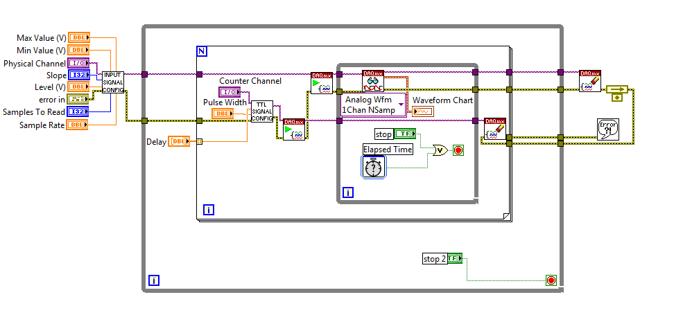
I am currently using a PCI-6251 DAQ card with a block of connection BNC-2120. I have a VI (one that is attached to this topic) that will essentially be an analog input signal and produce digital impulses from the output of the meter to each instant trigger. I am also able to define a series of delay values such that the delay will update automatically each at intervals specified by the user or when you press the stop button. I wonder if there is anyway to change this program as the time-out value will change every instant release. So, for example, in the first trigger a pulse is produced 0 second delay, then immediately when the next instant relaxation is reached, a push will occur with a 0.1 second delay, etc... And I want that the series of the time-out values to keep looping. I tried to use my current VI, with time to stop at each iteration to be less than half of the period, so theoretically it should go to the next delay value in the next instant trigger. Then I tried to put a certain time-loop around it to keep the job going, but it doesn't seem to work. I've attached a screenshot of my attempt, please let me know if this is possible, thank you! To see what each part of the VI in the screenshot, please see the screws attached, thank you!
P.S. for the VI that is attached, the analog input signal is 281Hz, the pulse width is 2.5% of the period and the delay is in the stages of T/20.
No worries,
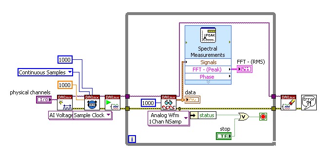
Please see the attached block diagram image. It is important to wire terminal on the Read.VI DAQmx acquire in a constant to the number ofsamples. This will force this function to wait until many samples are available in the buffer. In my example, you will get 1000 samples per second (because my rate is 1 kHz). and these 1000 were submitted directly to the FFT. What happened for example of you, it is only because you have not specified the number of samples to read, it is by default (-1), which means that the DAQmx Read.vi will pull all the data that is available in the buffer at the time. So if you had only 2 samples in the buffer that your FFT will have only two samples on average and as a result it will fail. Try this and it should help!
-
Well, I thought I had everything figured out, but we have finally had time to go to our lab and test it and there seems to be a problem with the output digital here. I'll look at what's the point of this VI, then describe the problem
Analog input is entered and analyzed as digital outpt is sent several lines (3). The digital output is used to send a single, user‑defined delayed pulse TTL with other instruments like triggers. I put this program to create an array of digital waveforms for each channel, each of them are of the same length as the analog input. '1' is inserted in the appropriate place in the table, in lieu of a value of '0', creating the required table. This table would be written on a digital line (1 channel, samples of N). Three of these subVIs are used here, so three signals various tables are created and writtin in its respective lines when the program runs, the analog input seems to work very well, but that a single digital output is executed. I need all three lines to write simultaneously.
I use a USB-6221 with LabView 8.2
I have attached all the files needed to run this program, and if the 'LabView programs' folder is saved on the C drive, I think that the paths of the files must be correct.
Thanks in advance
Hi Chris,
Hello and I hope that your well today.
Thanks for your updates.
I think that my being better if we start from the beginning.
1 could you try the example Correlated Dig writing with Counter.vi from the Finder of example of NOR?
It produces output meter as the time base for the digital output - to get clocked at digital output. Don't you see the waveform being printed on your outings that match the graph of digital waveform on the front panel?
If not, try to use one of the other examples, as Scripture Dig Port - this is a single VI just to send a single value for each digital line. If this does not work, there is a connection problem.
2. If we got this far without problems, then the next part would be to change the waveform so that you could write the data that you want to...
The digital waveforms can be made a boolean table, then using the array of Boolean DWDT to Digital.VI to convert into the type of digital waveforms. The waveform will have X number of samples. Therefore, at each clock pulse, you will produce 1 sample on each channel. So if you set the rate for 1000 and the number of points to 1000 (samples) it will display the waveform on a second. (as his continuous the DAQmx will make a loop through the buffer and start out of the waveform again).
Note, have you seen the palette of digital waveforms? It is located under waveforms and has more vi like the Boolean DWDT to digital.
Please let me know how you go.
-
Registration of the analog inputs in continuous (Clipping)
Material:
(1) USB NI CDaq-9174 chassis
(2) NEITHER 9234 Analog Input Modules
(1) digital input module 9402 OR
Goal/Requirements:
To read the analog inputs continuous only in digital input is "high".
Problem:
Timestamp in log file prooves that logging is not continuous. It seems that the first seconds of 0.6 of every second is recording, I guess the other 0.4 is used to write custom? I can't use VI SignalExpress for this application because logging must be triggered by a high digital input.
File is attached. Thank you all!
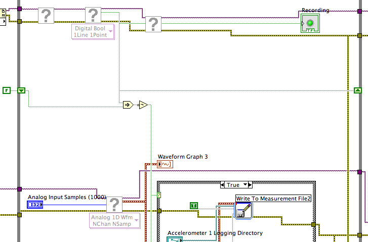
To detect changes in the digital input, you need to compare the current value to the previous. The easiest way to do this is to plug the output of digital playback on a shift register. The Boolean function involves will tell you when a transition has taken place. See the central part of the image below. If you exchange the true and the false case of case structures, you not the inversion function. Look at the help file for more information on what the function actually implies.
You must also change the wiring of the name of input for writing custom file FIle.vi so that the name is automaticlly changed. Depending on what you want the naming system to be, that it can be simple or rather complicated.
Lynn
-
Digital output to a different voltage?
Hi all
I finally finished my program of data acquisition for the laboratory, which made the acquisition of AI voltage multi-channel digital outputs with timed to control the gas valves. My post-doc asked an additional feature, however, which must be able to have the analog output... It turns out that what he really wants to do with the feature is to have output digital, but with a different voltage value (he never hears on the sending of information higher or lower in a simple experiment).
Now, the program is set up to run digital output now, it would be quite a bit of work to change in a zone of OCCUPATION. Is it possible to simply change the settings somewhere to have the ups to DO at a different voltage? I hope that this is the case from a card of 10 dollar Arduino can do 5V or 3, 3V. Our DAQ card is the NI PCIe-6353. I looked through the data sheet and found nothing.
Thank you.
p.s. I suggested using additional circuits to set the tension for a given experiment. The post-doc said it was possible, but inconvinient. :/
RaymondLo wrote:
p.s. I suggested using additional circuits to set the tension for a given experiment. The post-doc said it was possible, but inconvinient. :/
Well, it is just too bad for the post-doc. Maybe he should give you better requirements next time

OK without being in a bad mood, it is not a way to change the digital output voltage. When you talk about DIO cards really aims to communicate only high or low and have a voltage. The only other option would be to use 4 AO ports on the card and treat them programmatically as DO.
-
Hallo,
I use the following system:
- OR PXI-1044 with controller NI PXI-8109
- OR PXI-2564 switch module to turn on the monitor of my test device
- Data acquisition multifunction NI PXI-6259 to measure the signal that responded to the questionnaire jump
The two cards are the same - PXI trigger bus. For both, PXI-2564 and PXI-6259 I use DAQmx to set the reading and writing of the channels.
Now, I want to measure the time between the digital output, my unit turns and the analog input, which measures the response of my system.
I can't do work by myself, please help me!
I thank Ludwig.
Hi Ludwig,.
If you can't give us any VI we have difficulties with to help you.
Because I Donat knowledge how your program is mounted it is not easy to know where you should enter signals.
Here's a question similar to yours:
http://forums.NI.com/T5/LabVIEW/best-way-to-measure-time/TD-p/178704
and 2 external links:
http://www.ehow.com/how_8698983_measure-time-LabVIEW.html
http://objectmix.com/LabVIEW/385152-how-can-i-use-LabVIEW-measure-time-between-analog-pulses.html
-
Problem with a digital output in the information of an analog input
Hello
I use a SCXI-1000DC module with a module of the SCXI-1600, SCXI-1531 module and SCXI-1163 module to receive an analog of an accelerometer signal and a digital signal.
I claim that the accelerometer is constantly monitored, and the output is on when I want to, by an impulse that I comand in labview.
I use a rate 25 k and a 12, 5K samples per channel on DAQmx Timing.I notice in DAQmx read, if I put a sample of hight by channel, the output is not there when I want to, and if I put a few samples per channel, I exit when I want to, but the program seems to be slow with the passage of time. I don't know how I can solve this problem!
I'm sorry for my English, and I hope you can help me.
Thank you
Silvia
Hello Silvia,.
If you ask a larger number of samples, the labview diagram will stay longer in the DAQmx Read function, so the while loop runs slowly, and the digital output is updated less often.
I suggest that you use 2 separate while loops: one for the analog input and the other for digital output, so that each loop might run at a different speed.
Best regards
-
6009 outputs digital and analog input synchronization
Hello
I work in a program NI 6009. I want to leds by car with outputs digital NI 6009. For example, leads first will be on until what 200 micro seconds then second led will be on up to 200 micro seconds, and then first of all led will be on up to 200 micro seconds. I'll take led with photodedector signals and connect analog output photodedector input NI 6009. I want to synchronize the outputs digital and analog input and separate the first and second led signals the analog input for NI 6009 channel. How can you do with NI 6009? Please ADV
You can not do with the USB-6009 case. Its outputs digital are software with a maximum speed of slightly more than 100 samples per second. The outputs can produce 200 microsecond pulses and cannot be synchronized with the analog input.
You need a device with outputs digital hardware timed or counters that can produce a pulse outputs.
You can synchronize a bit digital output and analog input recording signal on an additional channel to HAVE. Will allow you to see the photodetector and LED the drive with the same schedule and such resolution as described by the sampling rate I. The maximum sampling frequency of AI on the USB-6009 case is 48 kHz that is shared by all channels. If you have two lights to led and photodetector two signals maximum sampling rate would be 48 kHz/4 = 6 kHz which is barely fast enough for your 200 US signals. For more than 4 channels, it won't be fast enough.
I suggest a simple oscillator circuit building and use it to clock a flip flop. This will give you alternating signals to drive the LEDs. You can use a line to reset the flip flop to give you control without the need for high speed.
Lynn
-
analog sync of input with the onset of the digital output
I'm trying out an analog signal to a file with a specified frequency samples. I also need a digital output to trigger a measurement at a frequency specified on a separate system. The frequency is controlled by the loop exits and timed when the iteration number divided by the period is exactly a whole number.
Both outputs work. The problem is that they are not synchronized. The analog output amounts to about 0.5 ms faster than the digital signal. (I checked with an oscilloscope) They both start in the 1 ms each loop runs for, but I really need them to start at the same instant. What can I do to synchronize? Also, if I'm going in the wrong direction complete, please indicate.
I use a card PCI-6723, which I think someone at some point, said not having a material sample clock. That's why I try to use a timed software loop.
Hi NEA.
You must use the 6723's built-in calendar to accomplish what you want. As the digital output subsystem is only clocked by the software, an appropriate solution should be to use one of the counters to the pulse output.
The attached code should show how. You can use the counter to output a pulse all samples of the AO N task. Material requires the initial delay to have a minimum of 2 ticks, so the meter will be behind the task of the AO by 2 samples in this case. There are different ways to work around this problem if you need (for example write two samples of 0 first).
Best regards
-
create 4 pulse digital output at the base of the ttl input signal
Hello
I am a beginner in Labview and would welcome advice on how to solve the following problem.
I'm setting up a train of pulses TTL and would like to send in Labview as input. Each falling edge detected on the input signal, I would like to as Labview to generate 4 pulse digital output. For each output pulse, I would like to be able to specify the period and duration. The image should illustrate more clearly, with the figures showing the expected scale.

System: NI PCI-6733 data acquisition card, Labview 8.5
My daq card has 2 timers 24-bit and 8 e / s digital, but I don't know what the best approach is to create between the pulse output of 4 to 8 of this precision... should it be handled at the hardware or software level? And how would I go about it
Thank you
-Sidney
Hi noli.
I found the problem, in fact PCI-6733 support only avoiding the digital output. The timing of software is limited to 1 kHz in case better.
I'm sorry, but this function is not possible with a PCI-6733.
Concerning
-
9174 triggered output pulses and analog input synchronization
Hello
I have a cDAQ 9174 with a 9215 analog and a 9401 module. I wonder if this configuration is suitable for my use: a trigger digital extern is sent to the system to trigger a task of analog input, trigger a generation of pulses, with another counter, count of trigger events. Using two counters on 9401, it seems I have no left Terminal at the entrance of my trigger signal. The trigger DAQmx vi does not show counters entries in the list of signals; and if I select a PFI line, an error that says that the line is already in use..., I missed a few obvious solution? I have change my 9401 to a 9402 did?
Thanks for any help,
Vincent
Hi Vincent,.
So, looks like you need a single line to use as input to trigger events and another line to use for a generation of pulse output. This should indeed be possible, since the 9401 has 8 lines that are configurable nibble (i.e. lines 0:3 could be configured as inputs, while the 4:7 lines could be taken out, or vice versa).
However, a big caveat with the 9401 is that the lines must be reserved before each task is started. This is a limitation of the direction of the line is implemented in hardware and is common as customers when something they using the 9401. Explicitly reserving your tasks before starting must correct the behavior if that is indeed what you see.
Best regards
-
Output TTL triggers analog input with PCI-6251
Hello, I'm new to LabVIEW and have a question that I hope I can get a response on this forum. I am currently using a PCI-6251 DAQ card with a block of connection BNC-2120. I would like raise an event on an input, for example a sine wave, which is connected to AI0 analog. Then I would send a TTL pulse train via the digital output. What I'm describing can be better understood by the images of this link:
http://zone.NI.com/DevZone/CDA/tut/p/ID/3017
In the tutorial page linked above, they do mention the card PCI-6251, but when I read the specs and compared, 6251 also has analog and digital Board, trigger functions, as well as digital I / Os... so I think he should be able to do what I want it to do. Can anyone confirm this? If anyone could help me by providing a VI that could do what I ask, just to help me get started, would be greatly appreciated. Thank you!
Hello!
Please post on the Forums OR! My suggestion would be to use build it digital Pulse - Retriggerable.vi found in the Finder for example of OR. Open LabVIEW, go to help > find examples > input/output equipment > DAmx > generating digital pulses > generate digital Pulse-redeclenchables. Change the type of trigger for this departure vi > Analog edge and make the source one line APFI (pin 20 of your card is APFI0). This will generate a pulse based on an edge similar to a level that you specify.
I hope this helps!
Maybe you are looking for
-
This just started today. (I believe that yesterday there was an 8.1 automatic Windows Update when I shutdown - don't know if that is related.) Anyway, when I click on a video VIMEO - video VIMEO ALL - everything I get is video (photo), but no sound.
-
My incoming mail is suddenly not be formatted; only the text is displayed. What should do?
Mail, including a line like 'click here to view the message in the browser' done the right thing, when you click on it, but not on arrival. Of course, not all incoming messages contain such a line. I guess I did something that caused this, but TB 24.
-
Hello I set up a password for the software on my computer but I forgot it & my password help is not helpful. I am running Network Magic 5.1.9055.0. I know my routers password and I made sure that I did not use the same password for the software. S
-
Advice needed on the upgrade of the OS
Hello. I have an Inspiron 5759 running win 10 Home 64 bit... I have an ISO of Windows 10 education of Dreamspark. I'm in two minds and would appreciate some advice. Firstly, I would like to completely reformat the hard drive and perform a clean insta
-
Run the .bar file in Blackberry z10
I have a file .bar with me... .can someone tell me how to handle this Simulator; I want also the format in which I sent this .bar file to my client... then he can run directly into the BlackBerry z10. Please help me in this... its urgent