Size of analog input to see the digital indicator cover
I read a channel of analog input with several samples, and I want the magnitude of which is playing to display on a digital indicator which is on my front. I know that it is not possible to wire just the data directly to a digital display of the signal due to the difference in the data type. Does anyone have an ideal on how I can get around that?
Dear Thuillot
You can use 'Extract only your Information' function found in the range of signal processing.
You can find more information on this feature here
Kind regards.
Tags: NI Software
Similar Questions
-
view table 1 d in the digital indicator
I would like to display the first item in the digital display and the next show in the second place, the second component of the digital indicator and so on.
How to get around doing tat?
Try this:
-
Synchronize the clocks of 2 PCI cards for analog inputs with e/s digital reference
I'm trying to synchronize the clocks of reference of 2 PCI cards so that the analog inputs are synchronized. However, my appilcation has also digtial e/s on two cards, and who apparently made the mistake DAQmxErrorResourcesInUseForRoute_Routing. This discussion describes a similar problem, but the solution was to just put the reference clock to the slave device, who had no other tasks running on it, so what mine does.
Is there way I can synchronize the clocks of refernce without interfering with the digital I/o?
Thank you!
PS: My application is in C++.
The reference clock is really a lower-level component that is shared by all resources on a given device. All tasks on a given device must use the same reference clock. So if you use DAQmxSetRefClkSrc for a task, you can use it to set the same value for your other tasks.
Best regards
-
Using the DAQ USB-6009 meter and an analog input voltage at the same time.
Hello
Currently, I'm reading the two channels of voltage with the USB-6009. It happens that one of the channels is the output of a digital coder, and it would be much easier to use it directly to the PFIO entry that is defined as a counter. The problem I am facing right now, it's that I can't use the DAQ Assistant to use the analog voltage to a channel and the digital channel counter at the same time. Once I put the DAQ Assistant to read the input from analogue voltage, I won't be able to add analog inputs. And as I put the DAQ Assistant to use the PFIO as a counter, I can add more entries to read analog voltage is.
I wonder if it is possible to solve this problem using the lower level data blocks? Another solution would be to read two channels in analog input voltage and that the use of Matlab to process data resulting from it, since I was not able to do the counting to work simultaneously with the acquisition in Labview to impulses.
Hope you guys can help out me.
Thanks in advance.
Using a simple wizard of DAQ is incorrect. You need one to acquire analog inputs and one for the meter.
-
How to upgrade the digital indicator with digital input
Hello guys,.
I'm trying to write code to do the following:
The P0.0 USB-6501 connected to a switch which is held at the top via a resistor.
The switch is pressed and I can detect the entry (my LED panel changes color).
I need to update a digital indicator (I think it's the correct vi I use) whenever you press the switch.
Any assistant will be much appreciated.
-
DAQmx: Analog input directly to the analog output at the hardware level
Hi all
I searched for a while, but I couldn't find any suitable implementation for what I'm trying to do. A person where I work introduced me to an interesting challenge. Is there a way to set up a DAQmx task (or set up otherwise an MIO Board) to route an entry directly to an output to the analog analog hardware level? You may be thinking, "why the hell would you do? To reduce the electrical complexity, a colleague would like to concurrently read an entry while 'reproduction' of its signal on analog analog output. I know that I can easily accomplish this while the buffering by the PC, but they are interested in ensuring that the output signal is also similar to the input at the level of KHz signal, by introducing a minimal difference in phase (shift buffering of the PC).
For the record, we have for most old maps of the E series here like the PCI-6070E (PCI-MIO-16-1). I was first asked if it could be done through SCXI, but I figured I would start by asking about the MIO tips.
This looks like a long shot, and I've never heard of someone at - he never did this, but I thought I'd ask to be sure!
Thank you
Jim
Hi Jim,.
With the help of our driver is not a means of generating data directly from the FIFO of AI, it must first pass through the software. You can try the following code to the output of one of THE duplicate on the AO line to see what kind of delay you can imagine. It is similar to your original with a few adjustments code:
Use delayed output Version of avian influenza in DAQmx AO
It seems you need to do, you might consider instead the search by using a voltage follower to isolate the Vout wine.
Best regards
John
-
Analog input base changes during digital output in parallel
Hi all
We use a USB DAQ 6008 to run a simple system. AI6 is connected to a motion sensor; digital outputs control a pump. We noticed that if we read AI6 without performiong of additional tasks, the baseline is ~0.17V and when movement is detected it comes down to 0.13V. However, if we read AI6 while performing outputs digital at the same time, the base line comes down to ~0.14V and when activated he descends to ~0.1V, i.e. the line base modified by 0.03. We do something wrong or is this expected behavior?
Thank you
Danielle
Danielle,
You may have a ground loop. If the current of the pump or even digital control for the pump through the Earth wire similarly that the signal of the motion sensor, the voltage drop in the common driver because of the current pump could cause an effect like you report.
Lynn
-
How to create different types of analog inputs without using the DAQ assistant?
Hi all
I would like to create multiple entries multiple analog channels of type... I mean I want to have the voltage of 5 and 2 channels of temperature...
However, I am not using the DAQ assistant. I use "create channel" vi.
Can anyone suggest me please how to do / I submit my VI for reference... I have 5 tensions, and 2 temperature characterized as showing these 2 two separate graphics...
-
Lose the analog input samples to the high recovery rate?
I got it. I changed to a life-long.
I then changed code so that I was counting the samples collected in the software and stops when I had them all. Previously I was following the task of tension HAVE with the Done.vi of task completion is DAQmx.
-
When I receive an SMS, the digital indicator does not appear on the text message icon. Why?
Once I receive an SMS, it should be a digital display on the icon of the SMS application that displays the number of messages unread I received. This is not the case. So I am unable to see that I have received a message, I don't have the text application open. No idea why this is?
Check the settings-> Notifications and see if the badge icon is enabled for this app.
-
display the exact value of a slide to the digital indicator whenever it is changed
the subject says it all
Right-click to digital exhibition
Ben
-
Decoration of the digital indicator?
Hello
Is it possible to delete this workers effect you get with digital boxes? Please refer to my image as an attachment.
Thank you very much
Go with the classic digital Simple command instead.
-
Hallo,
I use the following system:
- OR PXI-1044 with controller NI PXI-8109
- OR PXI-2564 switch module to turn on the monitor of my test device
- Data acquisition multifunction NI PXI-6259 to measure the signal that responded to the questionnaire jump
The two cards are the same - PXI trigger bus. For both, PXI-2564 and PXI-6259 I use DAQmx to set the reading and writing of the channels.
Now, I want to measure the time between the digital output, my unit turns and the analog input, which measures the response of my system.
I can't do work by myself, please help me!
I thank Ludwig.
Hi Ludwig,.
If you can't give us any VI we have difficulties with to help you.
Because I Donat knowledge how your program is mounted it is not easy to know where you should enter signals.
Here's a question similar to yours:
http://forums.NI.com/T5/LabVIEW/best-way-to-measure-time/TD-p/178704
and 2 external links:
http://www.ehow.com/how_8698983_measure-time-LabVIEW.html
http://objectmix.com/LabVIEW/385152-how-can-i-use-LabVIEW-measure-time-between-analog-pulses.html
-
6009 outputs digital and analog input synchronization
Hello
I work in a program NI 6009. I want to leds by car with outputs digital NI 6009. For example, leads first will be on until what 200 micro seconds then second led will be on up to 200 micro seconds, and then first of all led will be on up to 200 micro seconds. I'll take led with photodedector signals and connect analog output photodedector input NI 6009. I want to synchronize the outputs digital and analog input and separate the first and second led signals the analog input for NI 6009 channel. How can you do with NI 6009? Please ADV
You can not do with the USB-6009 case. Its outputs digital are software with a maximum speed of slightly more than 100 samples per second. The outputs can produce 200 microsecond pulses and cannot be synchronized with the analog input.
You need a device with outputs digital hardware timed or counters that can produce a pulse outputs.
You can synchronize a bit digital output and analog input recording signal on an additional channel to HAVE. Will allow you to see the photodetector and LED the drive with the same schedule and such resolution as described by the sampling rate I. The maximum sampling frequency of AI on the USB-6009 case is 48 kHz that is shared by all channels. If you have two lights to led and photodetector two signals maximum sampling rate would be 48 kHz/4 = 6 kHz which is barely fast enough for your 200 US signals. For more than 4 channels, it won't be fast enough.
I suggest a simple oscillator circuit building and use it to clock a flip flop. This will give you alternating signals to drive the LEDs. You can use a line to reset the flip flop to give you control without the need for high speed.
Lynn
-
Registration of the analog inputs in continuous (Clipping)
Material:
(1) USB NI CDaq-9174 chassis
(2) NEITHER 9234 Analog Input Modules
(1) digital input module 9402 OR
Goal/Requirements:
To read the analog inputs continuous only in digital input is "high".
Problem:
Timestamp in log file prooves that logging is not continuous. It seems that the first seconds of 0.6 of every second is recording, I guess the other 0.4 is used to write custom? I can't use VI SignalExpress for this application because logging must be triggered by a high digital input.
File is attached. Thank you all!
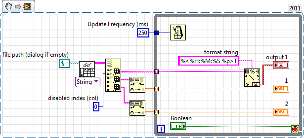
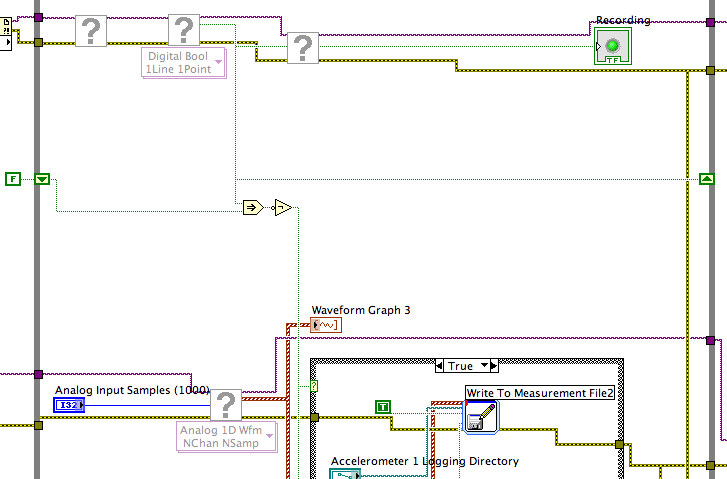
To detect changes in the digital input, you need to compare the current value to the previous. The easiest way to do this is to plug the output of digital playback on a shift register. The Boolean function involves will tell you when a transition has taken place. See the central part of the image below. If you exchange the true and the false case of case structures, you not the inversion function. Look at the help file for more information on what the function actually implies.
You must also change the wiring of the name of input for writing custom file FIle.vi so that the name is automaticlly changed. Depending on what you want the naming system to be, that it can be simple or rather complicated.
Lynn
Maybe you are looking for
-
I'm looking for the third order intercept point
How to find the point of interception of third order of my iphone 6? There is a sheet with all the technical specifications in relation to the my phone gsm modem. Thank you
-
Hi all A few problems trying to create spreadsheets with formulas. I made an effort and searched here and the internet for solutions but only partially successful. First, I know how total amount in a column and generate the result on another table, b
-
Hello! I recently bought a 2nd hand iPhone 4 in a store online, but thanks to a meet-up. The phone is good, and I got my Apple ID to this topic as well as on the iTunes. However the previous owner told me not to reset the phone, otherwise I'll be stu
-
Printer has already worked well. I replaced the black cartridge with the HP brand, he asked. He now says a driver is missing. How can I find and re-connect this driver?
-
Smart hard drive on computer error portable windows 7
I have a Hp Mini 2100-2190NR running windows 7. I had a problem recently where I couldn't boot into windows. I got it fixed with the help of a recovery USB disk. When I start my computer, I get a message from Smart hard disk error. It is said that it