analog multiple read arduino serial communication
Hello
I'm working on a project and I'm new to Labview,
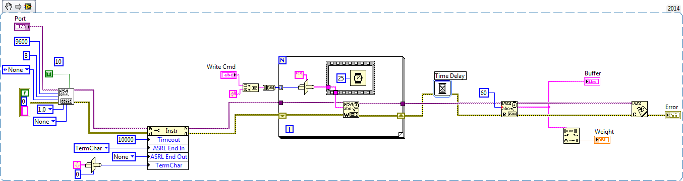
Can someone tell me how to read the multiple analog playback on Labview in communication series with Arduino UNO?
I tried, but data are somehow in error.
I have also attached my current code of vi and arduino.
Please help me.
Hello
You then send a value of more than your Arduino project. But in you VI you do not analyze the data entering split of voltage and current.
I suggest that you send a fixed string with voltgae and data current so that you know in your VI you will receive the number of bytes and how to divide the data.
Kees
Tags: NI Hardware
Similar Questions
-
VISA read very slow communication
Hello
IM using serial communications VISA in my project and I noticed that the reading block works very slowly.
I have the microcontroller that connected to my laptop through XBee modules.
Baud rate is 9600 due as a change factor in each component in the line won't make a difference at all.
Also, I checked that it work with terminal XCTU and its working fine (very fast). so his can not be something else except read VISA.
Please see VI attached file.Thanks for any help,
If you do not use a stop character, then the read VISA will sit and wait that 100 characters have been received by the COM port or the timeout elapsed (which is probably something like 5-10 seconds long). You can change the time-out period (using a property node) or reduce the number of characters you read each time that the loop runs.
Without a termination character, you will need to build your own string using a shift register buffer - whenever you make a VISA read, add it to the chain on the shift register and then do some analysis to take control of your microcontroller (e.g. alarm, coordinated) and remove all the foregoing orders of the string buffer (for example if you have started the VI in the middle of a command) ", then you don't want to throw these data).
-
Programming of the digital I/o pins on the NOR myRIO-9100 for serial communication
I use NEITHER myRIO for my robot and I want to use four reading of the distance sensors that communicate via the serial port. But the myRIO has only two UART ports on board so I was wondering if there is a way to program the digital pins use for serial communication. Any help appreciated.
It is possible. Here is an example that I could find.
-
Serial communication error VISA with LUDL stage controller
Hello
I'm trying to control a micro-positionnement made by Ludl stage. The model is Ludl MAC2000. It seems that the RS232 comunnication is implemented because I can talk to the controller using HyperTerminal. However, when I want to do the same thing through Labview, I can't answer the controller at all. The vi is roughly the same as the visa basic read/write in the example. Looks like a very similar problem in this post:
But the trick of nature of endpoint does not help in my case: I tried to toggle the termination character setting in the property node and different combinations of '\r', '\n' as termination characters, but nothing has worked so far.
Seems to me there is some difference between the interpretations of the same order to Hyper Terminal in Labview. But I just can't understand what it could be.
Anyone with a similar experience could give me some comments/suggestions? Thank you very much!
Another difference between hyperterminal and labview is the speed of sending characters.
LabVIEW breaks out the whole string to the controller
HyperTerminal is this character by character. So much slower and slow the controller can be affected by this.
You could add a loop around the writing of visa (to make it easy convert the string into a byte array outside of the loop and convert it to a string inside and you have a shipment char by char in LabVIEW
-
I use VISA 5.3 for reading my serial device... my standard equipment is WELL this device will send four messages of single command given to this instrument... and I read messages through VISA series READ... during the race, the VI buffer displays the messages individually... I need all four messages to display at the same time in VISA SERIES READ BUFFER, in order to find more than this block, I should add from the palette of function.
Disable character of endpoint detection or make four readings where you concantanate simply the strings together.
-
Read the serial number in LabVIEW of USB-8476 LIN Module
Is it possible to read the serial number of a USB-8476 module in LabVIEW. I am building a system that will use 10 of these modules in a single system and I want to be able to verify this LINX = serial No.: ABC. I'm afraid that a 'user' will disconnect and the plug-in a USB module causing the FLAX number to change.
Hi graveux,
The ncGetHardwareInfo.vi with the attribute set to "Serial number" should do the trick (use the desired USB interface and port number 1 as inputs).
-B2k
-
Serial communication - ignore parity error
I have a question about how LabVIEW opens a serial port for communication. I communicate with a device that uses a protocol owner. It sets and clears the parity bit to indicate the nature of the response. For example, the orders are sent with the parity bit higher while responses are sent with the weak parity bit (unless the answer is at the end of the transmission, in which case the device sets the parity bit high to indicate).
My problem is the way that LabVIEW opens the serial port for communication. Using Portmon, that I captured the control indicators, that it sends to Windows to configure serial communication:
IOCTL_SERIAL_SET_LINE_CONTROL Serial0 SUCCESS StopBits: 1 Parity: MARK WordLength: 8IOCTL_SERIAL_SET_CHAR Serial0 SUCCESS EOF:0 ERR:0 BRK:0 EVT:0 XON:11 XOFF:13IOCTL_SERIAL_SET_HANDFLOW Serial0 SUCCESS Shake:1 Replace:44 XonLimit:64 XoffLimit:64
Note the values 'Shake' and 'replace '. In my view, they are originally bytes with parity errors is removed. A separate RS232 Comm Debug tool that I use with success looks like this:
IOCTL_SERIAL_SET_LINE_CONTROL Serial0 SUCCESS StopBits: 1 Parity: NONE WordLength: 8IOCTL_SERIAL_SET_CHAR Serial0 SUCCESS EOF:0 ERR:0 BRK:0 EVT:0 XON:11 XOFF:13IOCTL_SERIAL_SET_HANDFLOW Serial0 SUCCESS Shake:0 Replace:80000000 XonLimit:128 XoffLimit:128
Notice the difference in values. By using this tool, Windows does not packages with parity errors - that's what I want. Is there any way to change how LabVIEW opens the serial communication port to achieve?
I tried to change the parity, where the ILO is defined differently, but I think that I am running in a race condition; LabVIEW can not run the code and change the mode of fast enough parity before the next byte of data is sent by the device.
Ravens fan: the parity bit, in the proprietary protocol, that I use, is not used for parity checking. Basically, the protocol uses a 9-bit serial communication. The parity bit must be paid or compensated according to what byte do (if it is a command, if it is the end of transmission, etc.).
I found an old post on this page which seems to answer my question (my apologies for not completely research before posting... I learn the right use/search phrases that I find more information). I download the 3.4.1 version of VISA now.
-
Read the serial number of the PXI 8130
Hello:
Anyone know how to read the serial number of an SMU-8130 chassis controller programmatically? Read the serial number of a 1075 chassis will work also.
Is it still possible?
Thank you very much
-Ilya.
My apologies, as this thread is expanded to LabVIEW, I was assuming that the main language was LabVIEW. Currently, it is not a condition C library that reproduced the personality of the Configuration of the system. My understanding is that this feature is in the works, but not yet implemented.
In the short term, you can choose to compile the necessary features of LabVIEW in a DLL called by your project. Otherwise, the MAC address can still be used as a unique identifier, if that's what you need.
See you soon,.
-
VISA + Serial Communication - need help!
Hello world
I have a lot of help with my project of this forum and I'm looking for more
 . Thank you for taking the time to help. Please bear with my as I ask a LOT of questions.
I intend to control a frequency converter using its series terminals and send orders from my PC + LabVIEW it. The commands do the basic functions like, start, stop, speed up/down etc etc. I use a converter Series USB to transfer data.
Now, I ve played with examples like SERIAL COMMUNICATION VI and others and I begin to understand the functioning of VISA.
Q1. In order for LabVIEW + VISA contact my frequency converter, do I need to install some sort of a driver for him to recognize? The frequency controller is old ages, even I don't know and I don't think I can find a driver for it any time soon? What kind of driver I'm looking for? Is it possible to customize my own driver and which would be easy?
accessory included - process.jpg
I downloaded some pictures about the problems of data format. I need to send information to the converter to format "telegram" as shown in the image below. Each 'function' in the 'format telegram' has varied length in bytes: some have 1 others have 2, other 4...
I also downloaded an image called "Format.jpg" which indicates what information each of these 'functions' will contain. Note:-the frequency converter uses only the last 4 bits.
Say for example:
START function will have this bit of information-
Start the Byte - ASCII ' 59 "
Address - 00
Control character -? I'm not sure what it should be I need to use the converter based on parameter values - is confused on what to choose - C, U, I or r Start, stop, etc. have their own specific parameter values such as 402, 404 RESP, so I guess I want update (U)?
Word of State control -? depends on the previous action
Sign - do not necessary
Data - 0
Comma - is not necessary
check the sum - is not necessary
Stop the Byte - ' > ' (ASCII: 62)
Phew... How would I go about clubbing this whole format together to send a control signal? Put all this information in a table allow somehow?
Please help to me... to achieve desperately need...
Thank you
Sandeep
It would be useful that you could find a driver, but it is not absolutely necessary to have a. You can write your own, use the Instrument i/o Assistant, or use VISA readings and some discreet.
The format of the commands is a bit complicated but not impossible. You just need to be careful to have the exact number of bytes.
What I don't see in the atttachments, it is possible words to control and the State and the number of parameter. I hope these are in another part of the manual.
A bytes example (without the control and settings) to update the frequency to 12.34 could be '<00U________+123403??>'.
-
Parity errors & read on Serial Port framing
Hello, I am writing a program that reads the serial port IR thermometer. Intermittently I get parity so many framing errors and can't explain why or find a way to remedy. All the parameters of the series were double checked and controlled. I don't get any errors when you use HyperTerminal yet, when I do test bed in MAX, I see these mistakes from time to time. I tried the suggestions of the knowledge base for these as presenting a delay between the Visa set up and read the Visa or flushing buffer issue before reading, but none worked. Any idea or ideas would be appreciated.
In addition, while searching through discussions on parity and framing errors, I saw a when a user recommends the following: "use wait event triggered by the stop character and when the error occurs, I just deleted the error, empty the buffer (wait the next stop character) and reread." If that sounds like a good solution, how would I go about its implementation?
I've attached a screenshot of my reading series loop so you can see what I'm doing. I do about the error code control timeout is.
Given that you have activated the stop character, you should not use the bytes to the serial port. You shouldn't have to delay or any function buffer flush.
PS, You also have to change the way your loop exits.
-
Sometimes the lost bytes, reading the serial port
Hello!
I'm reading the serial port data (flow rate 57600 baud rate) that works very reliable so that I do not open any other window
or minimize/restore my window of the application during the program is running. Then a byte of incoming data will be lost.
I get a string of 30 bytes each 50 m in most of the cases the first byte is lost, sometimes one in the middle.
This occurs not only on a PC.
Is this a problem of LabVIEW or Windows?
Are there settings that can solve the problem?
Best regards
JK78
I solved the problem.

There was a bug in my program who become visible only if a window has been reduced or restored.
When there are two or more messages in the buffer VISA, the separation of the messages was incorrect.
Array index corresponded to false so that the first byte of the second message was at the end of the first
and so the second message in the buffer seemed incomplete.
In normal operation, the playback loop runs so fast, never both messages are in the buffer.
Thanks for all replies.
JK78
Either way, I work with LabVIEW 2009 and serial interface hardware motherboard. With XON/XOFF flow control
is not possible in my application because all the hex values from 00 h to FFh may appear in a message.
-
How to read the Serial Arduino data using labview VISA?
Hi =). Im a beginner work reading data series from an arduino but im facing... Lets do it step by step
I built a voltage divider circuit which gives from output
from 0 to 5V. The output of this circuit is sent to a 0 analog input pin
of a Committee of Arduino Duemilanove.(1) Firstly, I connected the cable to connect to my laptop USB the Arduino.
(2) I went to start-> control
Control Panel-> system-> hardware-> Device Manager. Check the Ports (COM
& LPT). In my laptop I can see USB Serial Port (COM4). Now I know only in
LabVIEW that I must read the data series COM 4.(3) to the side of the arduino, here's the code to read changes in voltage
entered to analog pin 0. The last line of 'delay' determines the sampling
Rate of how we want to taste the output of the voltage divider:int potPin = 0; Select the input pin for the output of the voltage divider
int val = 0; variable to store the value from the probevoid setup()
{
Serial.begin(9600) (9600); Opens the serial port, establishes the rate of 9600 bps data
}void loop() {}
Val = analogRead (potPin); read the value of the voltage divider
Serial.println (Val);
Delay (10);
}I slightly modified the basis series reading writing VI... I have
attached the block schema used with comments. Basically, I tried to read
data series, divide by 1023 and multiply by 5 to graphic voltage
variations of the voltage divider circuit. But Im not getting
the correct voltage output values. The value of the tension just keeps go
0 and coming again, as shown in the photo.Could you guys please guide me on what went wrong?
Thank you!
-you read the data, even if there is no data on the port. If 0 bytes are read => «»
-in the case of false, you resources VISA wired for the output of channel tunnel?
-There is no close VISA at the end of the VI resources
-you're not a loop this VI reading bytes
I added an addaption of your VI that you should give a try maybe

-
Cannot read serial communication in OHAUS Ranger 7000
Hello
I'm reading a balance OHAUS Ranger 7000 data. Communication is via a virtual USB port (drivers came with scale). I have configured the port according to the parameters of their manual series. But for some reason I'm not able to read all the data. The process is either expire or I read 0 bytes data. I have attached the snippet here. I'd appreciate really any suggestions on this.
Thank you
Naren
I have tried several things and understood the mistake. The program worked when I wrote the one byte of orders at a time.
-
Can't get bytes of CPU to read in LabVIEW * FTDI * Serial Communication *.
I have trouble to get LabVIEW to display the bytes I send from a microcontroller with a FTDI chip.
Specifications of communication are:
baud-19200
-8-bit word length
-1 stop bit
-no parity
-no flow control
I modified the demo of the chain of read-write of the here just reading the chip. I see that a few bytes have been read in the indicator "bytes read" but nothing appears in the buffer. Any ideas? I may have something hooked up wrong or something wrong in communication specifications
-
Hello
I am trying to contact a Watlow F4D controller on a room using RS232. I use a cable converter USB-series and NI Watlow F4D Serial Driver.
The code of error-1073807339 occurs in:
Read in F4.lvlib:Utility MODBUS RTU Watlow VISA receive message-> Watlow F4.lvlib:Utility Register.vi reading
I don't know what caused the problem. I am able to see the cable converter USB-Serial OR max. Please see the pictures for more details
Thank you
Felix
Maybe you are looking for
-
Why portfolio is missing on my ipad
I don't see paying Apple and wallet in the settings on my iPad. I have updated to iOS 10 not have configured Apple paying it forward.
-
Now, I need to access information through the Tools tab page to make sure that the pages are safe to enter sensitive information.
-
Dynabook: How to enter the BIOS settings?
I have a CRC Dynabook V2/470. How can I get into the BIOSsettings on this laptop?
-
problem with the pavilion dm4 3002 laptop drivers its
I have a 32 bit win os 8 and my wifi and bluetooth drivers do not work help me
-
How to change music files in wmp
I am trying to edit multiple audio files in wmp before burning to cd. I would remove long breaks, etc. or other parts to improve the continuity of content.