Analog period measures
Hello
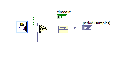
I need measure the frequency of the signal sinuoidal that is developed by using LabVIEW FPGA. I tried to use the block analog measurement period.
The value that I used are: 0 threshold, hysteresis 0.5.
However, no matter what the frequency, the period is always zero.
I also tried different threshold and hysteresis values, but it was in vain.
I would be grateful if you could be of any help.
Best regards, Keshav
Hi keshasvew,
This function has a valid output signal that becomes true once per period, so it is likely that you are actually getting a good result, but never see. You will need to add a bit of code to output that uses the valid output signal to lock the result of the last valid measurements. You should also monitor the timeout output, which will remain if you get no results at all generally true.
Tags: NI Software
Similar Questions
-
Period measurement error 20308
I'm trying to measure the period of a very slow rate (Hz 0,083) to come to my DAQ (6009).
However, it comes with "error-20309 occurred at the" NI_MAPro.lvlib
 ulse measures 1 chan.vi:2 "when it is called of" NI_MAPro.lvlibulse measures N chan.vi:1 "(waveform index 0 1)". "
DQA captures method is set on "on demand" however I also tried various (frequency + buffer) such as 10 k by 2 k.
but it always comes up with the error.
I know why it comes up with this error but do not know how to fix it.
I have attached the vi (the signal to simulate reply my DAQ)
Because you'll probably want at least 2 cycles whole to your measurements, and each cycle lasts approximately 12 seconds, I would get 25 seconds of data at 50 Hz (1250 samples)
-
multi meter PCI-6602 daqmx semi period measurement
Hi all, currently I am working on 20 channels PWM. I have a problem on my labview code. Would anyone give some advice on my vi? I packed for 2 channels labview code, for now. I do measure period semi. I want to measure the cycle frequency and the duty of the PWM signals. But when I run it, it has error. Please give some tips where I did wrong on my vi. Thanks, Johnny
Marconi salvation,
This error you are getting is a buffer overflow error and is probably due to the value that you used as an input for "number of samples" on the reading DAQmx VI. You set it to 4 but according to how fast the PWM you read is, you can acquire values in the buffer on board much faster that you collect with the reading DAQmx VI. Then when you call the DAQmx Read VI, who reads from a pointer to read the data you plan to read the buffer has already been replaced. One way to get around this is to increase the number of samples to read whenever you call the DAQmx Read VI. I tried your VI and managed to do work with a slight change to the trigger start (using the PFI0 instead of the time base of 20 MHz) and added a loop condition to stop making a buffer overflow error as well. Take a look and see if that helps. In addition, why you fire off the coast of the time base of 20 MHz? is there a particular reason? It is essentially similar to using no trigger starting since you should get the first front of this almost immediately after the start DAQmx VI is called. I'm just curious, since using this trigger from the beginning has not actually worked for me (although I look into why).
Chris W
-
Helps with 7852R input analog voltage measurement
Hello
I'm trying to measure three signals of tension off a QPD, the three signals are connected to the IA the SCB - 68 and then I used the example of vi to acquire analog inputs with FPGA R in the finder of the example. However, I make a range of very large numbers. I don't know how to convert these volts or what are these numbers, units... etc.
Any help with this, please?
Thank you
Hi Biochemist_MU
Please take a look at the forum post FPGA of analog input and output scale. It deals with the scaling of the R-series cards.
Hope this helps and let us know if you have any other questions.
-
Analog inputs measures with NI6229 using the DAQmx driver
Hello
I have four different analog inputs connected to ai0 to HW 6220 ai3. I read these values with a single task, all 4 channels assigned to this task. When ai0 reads 7V, I see 0.8 V ai1 too, but I expect to be measured 0V. If I just assign ai1 to the task and measure all 4 channels, then I measured 0V as expected (although ai1 contains 7V, I just don't measure it).
Another comment 'funny', is that if I change the order in which I add channels to the task, measurement errors are different.
However, when measured with a multimeter 4-channel show tensions as expected.
Given that my calling task is can not block, I call the function
DAQmxReadAnalogF64 with timeout = 0 and numSampsPerChan = 1.
Any help is appreciated.
Thank you
Kind regards
Deepa
Deepa,
Thanks for the code snippet.
When you call DAQmxReadAnalogF64 the first time and you set a value of timeout of 0, there is a chance that the acquisition is not yet initialized. This is the expected behavior and should not be a problem. If the timeout error died at the first call, you might ignore it or set a different expiration time for the first call only. In all cases, you should drop the first value and start with the second value.
Jochen
-
period measurement Semi USB 6221
Hi guys,.
I have a problem measuring the period of semi of a digital signal. I'm gernerating a pulse with my USB 6221 DAQ board and I use the counter 0 (9 PFI) for the period of semi. But I don't get all the values. Also, I tried to generate a signal of pluse using the 1 meter and measured the period using counter 0 and it worked perfectly fine. Take a look at the code can be I am doing something wrong.
found the problem. I was reading more samples then I sent.

-
How to 'READ ONLY' on the combination of period / measure
Hello
I want to restrict expenditures-> FY09-> 7-> cost of a 'READ ONLY' column
and allow updates to columns other predictions-> FY09-> Oct-> cost in another column. Can someone help me? I want to give users access to write custom 'Recipes' for all the months and the years of FY09.Hello
It's your last post:- How to organize columns form
If you create lines or asymmetric columns, you will be able to define which ones you want to read-only.Ok?
See you soon
John
http://John-Goodwin.blogspot.com/ -
FPGA "mean, Variance & Standard Dev ' VI
Hello world
I use the express VI 'average, Variance & Standard deviation' through the vessels: 130 samples of a given signal. When I run the program, the Boolean value "True output" is always false. Does that mean exactly? The output looks like valid... This VI documentation is pretty poor. Someone can explain what that output tells me?
Thank you!
-Alec
Hi Alec,.
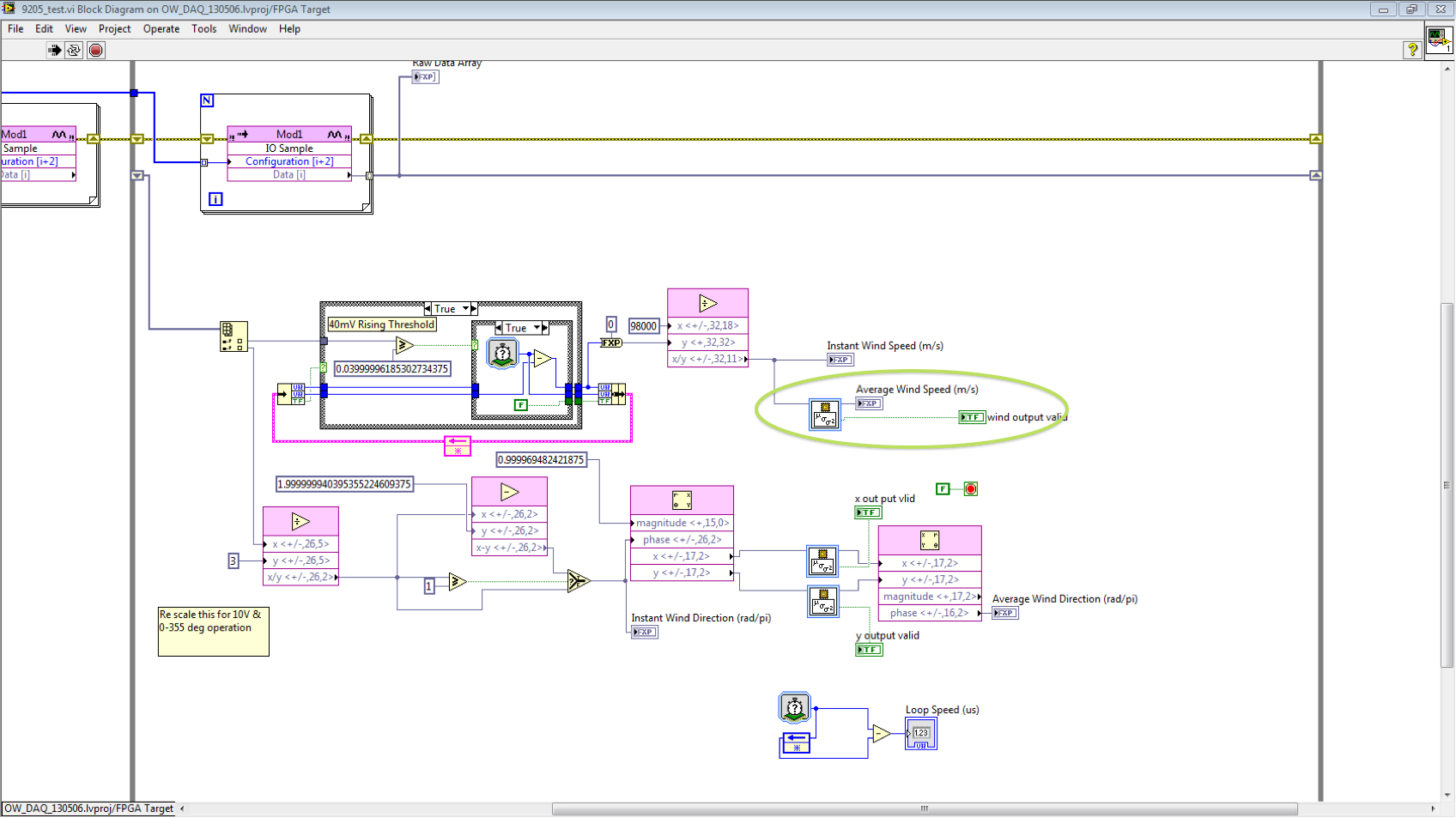
OK, I now see the source of confusion. This VI does not support running averages - that's what we've been referring to as "image-based", producing a single measurement for every 130 incoming samples result and a single pulse of the valid data for every 130 samples of output. This mode of operation is similar to the screws based on the Bay (Mean.vi, etc.) in mathematics > range of probabilities and statistics, that take a table and a scalar output. The only difference is on the FPGA, we need to disseminate, in the table, a point at a time. That ye (a reasonable expectation) is analogous to the PtbyPt.vi means that takes a scalar input and updates the average result on every call. We have implemented the version based on the first frames because it avoids the need to store all of the table. To see exactly what we do on any of these screws, just right click on the node and select "Convert to the Subvi", where you can consult and/or modify the code to suit your needs.
For an example showing a similar operating mode, you can view the example analog period measure (measure Control\Period and examples\R Series\FPGA Fundamentals\Analysis). This example shows an external logic added to lock the result for each period measure - that you have already seen, it is not necessary for average, Variance & gap since this locking is done in-house.
If the documentation clearly explains the behavior above, which should meet your needs or is there anything else you would expect to cover?
I'll submit requests for corrective action on the absence of an example and documentation for clarification.
Thanks for the comments!
Jim
-
Period with external clock measurement
Hello
I have the USB-6210 and I'm using Labview 8.0.
I use the 6210 for period measurement of a signal. I have another card (not OR) I want to synchronize with the 6210. The other card has a clock of 10 MHz with a TTL output.
I am trying to use the 10 MHz TTL of the other card as an external clock for my measurements (this would essentially be synchronize both). The measure of the time does not support external clocks. I can't make the edges of the county if not work. Any suggestions? Is it possible to sync the 2 cards? If this is not the case, what are my options?
Thank you very much
Eyal
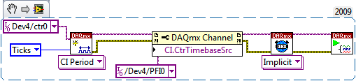
Hi Eyal,
How did you get your task configured? It should look like this:
Best regards
-
Measurement of voltage deferred with a start from a pulse TTL (PCI-6251, OR DAQmx)
Hello
What I do: gain a measure of tension after a certain period of time (order of microseconds) when we observe a TTL pulse, lasting about 1-100 microseconds. What are the options I to do thins?
PS. If this problem is solved in a C code example, please point me to the right direction. I saw examples of NOR-DAQmx, but not a not spot something like this.
Hi hum-human resources management.
The example of DAQmx ANSI C Analog In\Measure Voltage\Cont Acq - Ext Clk - Dig start shows how to use DAQmxCfgDigEdgeStartTrig() to activate a digital start trigger. It also illustrates the continued acquisition, clock to external sampling and all events of samples N; for a simpler starting point, look at analog In\Measure Voltage\Acq-Int Clk-Anlg start and try to convert to using digital analog INSTEAD of triggers.
However, this will start acquiring exactly when the trigger occurs, not after a period of time fixed. Use DAQmxSetStartTrigDelay() and DAQmxSetStartTrigDelayUnits() to add a fixed delay between the trigger and the beginning of the acquisition. Help OR-DAQmx C reference (which should be on the start menu under National Instruments > NOR-DAQ) lists the valid values for the property of units.
Brad
-
Delay between angle and entered analog on a 6221
Hello
my test setup consists of a (8184 current run LabVIEW RT) embedded PXI controller which uses a PXI-6221 of data acquisition. One of the outputs analog of the 6221 creates a demand for speed that is sent to a servo controller. the servo drives then the test configuration. Between the servo and the remaining test configuration, a quadrature encoder is located. Both the 6221 meters are used to measure the position of the servo (using the trains of pulses A and B) as well as the speed of the servo (frequency of A pulse train). In addition to these counter inputs, some analog inputs of the 6221 serve as well to recored the configuration of test signals.
In this configuration, one of the analog signal has a frequency of n periods per revolution of servo (determined by the mechanical design of the test facility). But when I leave the servo turn to for example 100 rpm, then decelerate from status quo with a constant deceleration and then draw the analog signal against the measured angle, I see clearly that as long as the speed is telling, I n periods per turn (or a passage from my analog AC to zero each 1/2n towers); However, as soon as the slowdown begins, the plot gets stretched along the axis of the angle (so the plot tells me there are less than n analog periods per turn, which is impossible because it would require the mechanical destruction of the facility).
However, I can calculate a position based on speed information signal, as I got to the second counter (by integration of the speed). When I do this for the above velocity profile and draw the analog signal against the calculated angle, I see exactly n times / revolution, no matter how fast the installation program is rotating (just the expected behavior).So, apparently, the speed measured is "in phase" with analog signals, while the measured angle has a "phase error. Draw the angles measured and calculated against the time tells me the same thing: the measured angle is always late (compared to the calculated angle). The period is not constant throughout the measurement; I've seen values between 30 and 170 ms within a single record. Due to this change of variable, inserting a delay for all channels, but the angle is not a great idea.
Unfortunately, calculation of the position of the speed signal is no option for me, because the direction of rotation is changed during measurement; because speed information I have based simply on a frequency of pulse train, it contains no information management, therefore a calculated position would be unaware of the changes of direction.
Does anyone have an idea whence thios delay and what I can do to fix this problem?
Try a position different methods of decoding or exchanging the meter channels has not made a difference.Thank you!
Hey Kevin,
attached you will find the last block diagram (no new translation this time, since no changes have been made that require a), which includes your last suggestions (explicitly start the task of AI, remove the excess constraints) with a flat sequence structure that applies all the preparations of task to finish before the start of the first task (I know I could have achieved the same effect of intelligent routing of the signal error, but I think the code is) better readable this way).
Without OPI, LabVIEW tends to start to have, ao and tasks of the angle of the very different moments, which (for some reason that I don't understand - we have a sample clock based calendar here, and the sample clock is run, well after the three mentioned tasks...) tends to cause delays in the order of several 10-100 ms between tasks. With the structure, this problem is eliminated.
The Sub - VI just above DAQmx writing contains the "conduct" code that I used in the last screen shot to "serialize" the requested speeds - in this way, the table that contains the requirements of speed does not need to be rebuilt.
The code that creates a weather channel frequency implicitly timed measure left the VI shown here in a second VI that is running on the host computer, because everything that involves a calculation and does not require any intzeraction with the DAQ hardware is better placed there (the 850 MHz on the PXI controller celeton is slower than 2 definitiely something host GHz Dual-Core system).
The behavior you mentioned for the task "not started" HERE is what wrote using LabVIEW. I thought the block of relaxation that I had at the beginning would treat the start of the task - at least, the code like this figure repeatedly in the examples that come with LabVIEW.
I don't really understand what has caused the problems I've had - it seems that it was the combination of the measure quickly loop iteration with the start of task based on trigger HERE, but I do not understand what are the mechanisms in the background caused the problem (too forced loop was not the cause; the same block diagram works well with an additional loop timer).
If the solution was composed of the following steps:
-remove the old code calculating speed, replace it with a better code out of the main loop. This allows to
-reduce considerably the frequency of the main loop.
-Pull the DAQmx writing out of the loop, and
s ' ensure that all tasks are started explicitly just before the main loop starts to run.
-Possibly remove excess constraints of the main loop.
-
Count of edges within a period
Hello
I'm still fairly new to labview and that I could use help on something, I'm working on.
I need to measure two things of an encoder, the RPM, which I can easily do it through the index; and the number of edges on the channel between two pulses of index.
I would like to use the index to trigger the counter to start to count the edges on channel A, then the index following the end of the counting. This program will essentially allow check the speed of ROTATION of the encoder based on a basic speed, and it will check for the proper resolution of the encoder.
I use a NI6602 counter card and I need to be able to set up several top encoders that's why I'm only using the index and the channel has.
Thank you
Jason
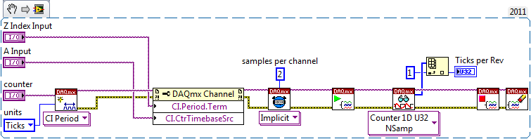
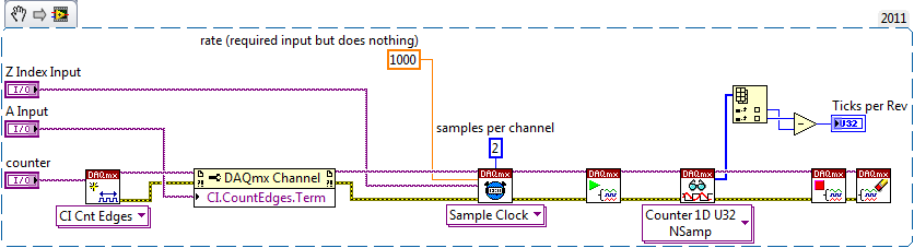
You can either:
Configuration of the task as a measure of the 'period' (measure the period of the Z index by channel A time base):
OR
Configuration of the task as a measure of "County Board" (count of the edges of a signal using the Z index as the sample clock):
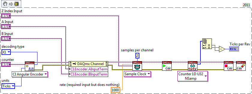
OR
Configuration of the task as a 'encoder' measure (measure the change in position in terms of A / B ticks using the Z index as the sample clock):
But the example of encoder, you probably want to configure the digital for each input filtering as encoder in all signals are often quite loud (sometimes the noise is detected as additional edges that would shake your meausurement). In the example of the encoder, it is probably not necessary given that the meter is incremented only once a cycle of A and B even if you still need to beware of noise on the Z index signal.
Best regards
-
Complete noob - would like to measure the voltage to manual start and stop
Hello
As the topic says I'm a complete noob when it comes to programming OR.
I'm looking for someone to point me in the right direction
Installation program:
Windows8 office
Visual Studio 2013
NI 6255 PCI data acquisition card
Block connection OR SCB-68
What I want to do:
I want to write a console application to measure the voltage on the signal ai16
-I want to be able to start and stop the application manually
-I want to be able to pressure measured in a CSV output.
Where I am:
I compiled and ran the example "NOR-DAQ\Examples\DAQmx ANSI C\Analog In\Measure voltage.
It is said that I have "collected" samples but I don't know what that means, as I do not see an output file...
What I don't understand:
Samples - I do not understand cela or know even where to start
How can output file - I get the file to save the collected data.
Thanks in advance
Chad
Hi Arron
Thanks for the link, unfortunately, it has not helped because the instructions were for Visual Basic and C++ not. It was my fault for not putting the language of prog that I need help in my original post.
However, I started to find help on this link: http://www.ni.com/tutorial/5409/en/
-With the help of NOR-DAQmx in text based programming environments
-
Data acquisition period log rate Counter
I measure and record the duration of a pulse train of digital entry (entry to the NI9421 card on a DAQ, series "C" chassis and recorded via LabVIEW SignalExpress 2009). The acquisition stage 'Counter period' is configured to use ' 1 meter"measuring method.
In order to save the data that I have to use ' 1 sample (on request)"acquisition mode.
When I go through the saved data, how can I determine:
(a) the sampling frequency of the recorded data points?
point b) absolute timestamp of all the data?
The log file has no information concerning the frequency of recording and my experiences, it seems to change based on the measured period of entry.
Any ideas?
Hi a.yearsley,
Counters on cDAQ chassis 1st generation (9172) do not support measures clocked sample period. I assume you are using this chassis since you mentioned that you have the module in slot 5 or 6.
Your County of edge is very similar to the method of meter high frequency 2. In both cases, you specify a length of time and count the edges of your external signal during this period. The 2nd counter is used to generate the gate signal for the duration of time specified. Your error with this method is up to 1 time of the external signal, it is more commonly used with higher frequency signals (I don't know what is the frequency of the signal).
The standard method of 1 meter counts the number of ticks to a time base internally (80 MHz) for a period of the input signal. As the signal itself, it is what is blocking the measure, the sample is locked in the buffer on the edge of the signal and is not clocked independently. If you wish, you can configure the implicit synchronization, which gives you a period measured for each face of the input signal.
Taking the stage above an idea more far, you could just set up a task to County of edge with the time of 80 MHz as the source database. Use the external signal as a sample clock. The only difference between this and using the standard period with implicit synchronization measure is that the counter is not reset after each sample. This could make it easier to follow if you want to save a sample all the x seconds (that is, once the total passes a certain value). You can find the period by subtracting the consecutive numbers and multiplying by the period of the time base (12.5 ns). The meter would be turning after 53.69 seconds about, but if you read the County under the name of U32 there will be no problem with the subtraction (0000 - FFFF = 1 if the numbers are 32).
If you're on cDAQ chassis 2nd generation (e.g. 9174, 9178, 9188), then you have not actually taken in charge for a period clocked sample measurement. You can choose to enable a medium or not. The user manual 9178/9174 has diagrams showing the extent of the clocked sampling frequency that is essentially the same thing (the driver reverse the measurement period for the frequency). Must be guaranteed at least 1 m from your external signal between the sample clocks, if you use this method. The clock can come from many sources - I would probably recommend using another counter to generate.
Best regards
-
Detection of the contours of a measured waveform
Hello
I'm trying to detect the edges of a measured waveform. My ideas using peak detection or threshold has failed. Attached is an example of a waveform. I try to find edges, marked of a cursor.
I would be very happy if someone has a good idea.
Thank you very much.
Best regards
Michael
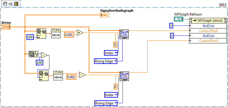
You can change the enum to the VI edge detector to detect the rising or falling edges. You have only to increase edges in your current signal, so you might find the signal low medium and medium high signal and find where the data that passes through in both places. I moved the thresholds of 0.001, but you would need to define an arbitrary passing threshold so that it is not triggered by the noise.
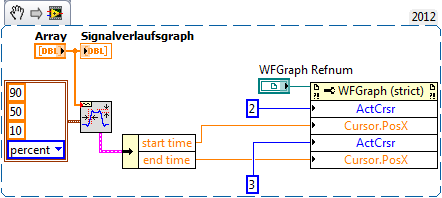
You can also use the VI transitional measures in waveform > Analog Wfm > measurements. This VI allows to specify thresholds in percentage of the transition (or absolute value) and find the start time and the end time of the transition.
Again, be careful with the effect of noise in States of high/low if you try to measure the transition points near the levels down.
Maybe you are looking for
-
NB100-10 X Windows Installation
I bought 2 Netbooks NB100. (Ubuntu) Now, I want to install winxp. I used a DVD. external Windows installation has started...--> bluescreen. I used a bootable USB key. Windows Setup-> blue screen. Other Versions of win the same thing. Another DVD - RO
-
How to set the parameters of the AKD with LABVIEW driver?
Hello I am looking for a simple example to set or read the AKD with Labview driver settings. The AKD has ethernet communication and control is analog - AKD-P00306-NBAN-0000 I want to use Labview to read the paramerters even as Kollmorgen WorkBench Th
-
The case of the laptop began to divide by the left hinge. Now, every time I open or close the cover, the slot opens. Is it possible to get this repaired? I love this laptop and it can be fixed somehow hope so. I bought it renovated less than a year a
-
I have windows vista and Trend Micro antivirus... I have a fake antivirus program which swept out of my system. We have fixed this, but I can't use Internet Explorer (but google chrome is ok) and when you click the start here button where there shoul
-
print drivers to 64 bit Windows 7 for IBM InfoPrint 12
I have an old IBM InfoPrint 12 printer attached via a USB cable for my new Windows 7 PC. Can provide you a link to a print driver so that I can make this work with my new computer? There may be a generic driver that would work? Thank you very much