Data acquisition period log rate Counter
I measure and record the duration of a pulse train of digital entry (entry to the NI9421 card on a DAQ, series "C" chassis and recorded via LabVIEW SignalExpress 2009). The acquisition stage 'Counter period' is configured to use ' 1 meter"measuring method.
In order to save the data that I have to use ' 1 sample (on request)"acquisition mode.
When I go through the saved data, how can I determine:
(a) the sampling frequency of the recorded data points?
point b) absolute timestamp of all the data?
The log file has no information concerning the frequency of recording and my experiences, it seems to change based on the measured period of entry.
Any ideas?
Hi a.yearsley,
Counters on cDAQ chassis 1st generation (9172) do not support measures clocked sample period. I assume you are using this chassis since you mentioned that you have the module in slot 5 or 6.
Your County of edge is very similar to the method of meter high frequency 2. In both cases, you specify a length of time and count the edges of your external signal during this period. The 2nd counter is used to generate the gate signal for the duration of time specified. Your error with this method is up to 1 time of the external signal, it is more commonly used with higher frequency signals (I don't know what is the frequency of the signal).
The standard method of 1 meter counts the number of ticks to a time base internally (80 MHz) for a period of the input signal. As the signal itself, it is what is blocking the measure, the sample is locked in the buffer on the edge of the signal and is not clocked independently. If you wish, you can configure the implicit synchronization, which gives you a period measured for each face of the input signal.
Taking the stage above an idea more far, you could just set up a task to County of edge with the time of 80 MHz as the source database. Use the external signal as a sample clock. The only difference between this and using the standard period with implicit synchronization measure is that the counter is not reset after each sample. This could make it easier to follow if you want to save a sample all the x seconds (that is, once the total passes a certain value). You can find the period by subtracting the consecutive numbers and multiplying by the period of the time base (12.5 ns). The meter would be turning after 53.69 seconds about, but if you read the County under the name of U32 there will be no problem with the subtraction (0000 - FFFF = 1 if the numbers are 32).
If you're on cDAQ chassis 2nd generation (e.g. 9174, 9178, 9188), then you have not actually taken in charge for a period clocked sample measurement. You can choose to enable a medium or not. The user manual 9178/9174 has diagrams showing the extent of the clocked sampling frequency that is essentially the same thing (the driver reverse the measurement period for the frequency). Must be guaranteed at least 1 m from your external signal between the sample clocks, if you use this method. The clock can come from many sources - I would probably recommend using another counter to generate.
Best regards
Tags: NI Products
Similar Questions
-
Hello
I have a power meter which provide the USB driver and a Labview program to get the data and NI USB-6221. The project I am currently working on the needs of:
1 acquire two signals (inputs of simple tension), pressure frequency KHz
2. acquire a flow signal, the output signal is 0 to 5V pulse, each pulse means 0.4 ml volume. So I use a voltage inflows to count impulses in certain period of time (in this case, 1 S) for water flow. ; KHz sampling frequency and the 1 Hz update rate
3. acquire a signal of engine speed. The output signal is pulse square wave whose frequency is related to the speed. I use a REIT port to measure the frequency. Sampling rate: Auto
4 give output voltage sine or square wave, I use AO do that.output rate: Auto
5 acquiring by VISA electricity meter data. Data update rate: every 50ms
Currently, all the 5 tasks work well separately. But when I put them together, some signals are beginning to hang, for example, pressure signals sometimes give nothing.
Another problem is the data record. I programmed the VI in such a way that whenever I press the button 'save start', he begins to record data and save them in a .cvs file. For some reason, I always get only the data in the first table. Coult someone help me? I download my code as follows
Hello
What I meant by open, write, close. For any type of file you are using.
Open the file, which produces a reference, then put the mention in a registry to offset.
Write data, using the function write (for this type of file) and the reference.
When you are finished, close the file reference.
Writing in the spreadsheet opens, written, close all at once. It is very good for this type of application.
***
The issue of the loop is more general. I would like to say first of all, I want to say that since each loop works on its own, it is own VI, and that this program has put all this into a single VI, which has a method to solve the problem is to disable all the loops and allow them one at a time to see if there is a culprit responsible for.
Using multiple loops executes the code at the same time, and some loops would be cycle faster than others, especially if some of them are loops just as they are.
Communication between the loops is a test to the address if necessary.
Running all these signals through different loops DAQ must also be examined. Don't know what questions are for read and write somewhat randomly in the channels.
-
data acquisition won't taste at the specified rate
Material: C - DAQ 9178, AI 9239, inside a servo and an encoder potentiometer module
Setup: I use the 9239 to measure the angular position of my servo and encoder of trees by streaming came pressure pot of the servo and my encoder. I put the sampling frequency on the DAQmx - Schedule VI to 100 Hz.
Problem: I don't think that my DAQ is sampling data at 100 Hz because my VI registers more than 10 000 data points for a 10 second test. In addition, every time I have save my data in a text file, the vector of time my test data resets after a number of iterations.
To debug, I tried the following configuration:
I've defined the sampling frequency of 100 Hz (or is that s/s?), the samples per channel (size of buffer for continuous mode) at 2000 samples, number of samples per channel up to 10 and loop milliseconds timer on my VI at 10 m accordingly, data acquisition would send 100 samples per second (or 1 sample every 10 ms) on my PC buffer (which could store 20 X that amount). Then LabVIEW would read up to 10 samples per loop iteration (which is itself ~ 100 Hz) and work with these 10 samples inside the loop. However, since the loop is operating close to the sampling frequency of data acquisition, then LV should only work with 1 sample each iteration of the loop (100 Hz / 100 Hz)-not the 10-sample-max that I specified.
However, I stumbled on "error-200279: the application is not able to cope with the acquisition of material" when I ran the program. Why?
My code and materials should be easily able to cope with data acquisition - at least the way I put it in place
This whole situation wondered my fundamental understanding of data acquisition timing, so I would really appreciate an explanation of exactly how to deliver DAQmx uses data synchronization, why my DAQ sample at 100 Hz, and how can I fix the calendar specified by the user.
Thank you!
aeroAggie wrote:
The C - DAQ 9178 there some minimum sampling rate I will not meet?
It's actually the 9239 that limit your sampling rate. Read the data sheeton page 5 there's available data rates. In short, your data rate allowed is 50kS/s / n, where is goes from 1 to 31. 50 k/31 gives you 1.6kS / s. So, it's the minimum sampling frequency that can be used.
-
Conversion rates for simultaneous data acquisition
I use a Mech multifunction data acquisition. / s/SMU-6366. The maximum sampling frequency for the analog inputs is 2 MHz. Is the time of actual conversion of CDA always 0.5µs, or t - it change with the evolution of the sampling frequency? Can I set the time of the conversion? Reading, looks with peripheral multiplex, you can set convert it clock and the sample separately clock. What is with simultaneous data acquisition?
Hi Daniel K..
It is a big question. I wonder if you get any errant behaviour - your card is not up samples as you hope?
Here is some information that might help you:
Wikipedia: successive approximations ADC
I'm not sure exactly what happens, but dare a guess time digitizing ADC does not vary with the frequency of sampling. And it will also be more than 0.5 US - it is more than likely faster than that.
I hope this helps. Good luck with your application!
-
motion control for vertical actuator and data acquisition
Hello
I am a researcher (a branch of civil engineering) geotechnical engineering and I have very little knowledge about the acquisition of control and data motion, so would need a lot of help from the experts OR. I have only knowledge base on these 2 aspects based on my reading of some materials on the Web site of NOR and youtube videos, so I hope that you bare with me
 . Here are my questions:
I am trying to build an actuator which will be used to push a probe (a penetrometer with a load cell to measure the resistance of a soil sample), resembling the concept, photography in the attached file. I need to have these criteria for my system:
(1) actuator, which can push the probe at speeds between 0.01 mm/s - 300 mm/s with precision and move the probe cyclically (upwards and downwards) in the vertical direction
(2) load expected on the probe into the ground range: 0.02kN - 6 kN.
(3) necessary to get the load cell load data and the speed of the probe.4) able to control the actuator to a PC (speed and posotion) and monitor data from transducers and data log time even the transducers.
Guess my beginners is that I will need:
For orders:
(1) software - LabVIEW and NOR-motion assistant(2) controller - NI PCI-7342
(3) driver/amplifier - analogue servo AKD Drive
(4) motor - motor brushless servo AKM
For the acquisition:
(1) software - based LabVIEW development systems(2) amplifiers or other device - no idea what type on the conditioning of signals
(3) data acquisition device - no idea what type
Since I'm a beginner, is - that someone might recommend components (hardware and software) for the control and data acquisition. I'm on a tight budget, so I thankful if someone could help me to recommend components good enough to build my system.
Thanks for your help.
At these rates, you will need to run the sensor for the cDAQ. You can configure the analog output on the Tritex nationally on the position. There is an adjustable filter that you can set in order to get a clean enough to 300 Hz signal. When you learn about the Tritex, make sure that let you them know what comms and e/s that you want to use. If I remember, not all options have worked together. The analog output may need to be my, but you can put a resistance through the acquisition of input data to get the voltage instead. I don't remember all the details. You should really not too much on the Tritex/LabVIEW side. You will send your movement parameters (beginning of end of race, speed, position, accel, cut), and if you cycle (I believe you) or simply running in a loop. You could also just be able to use the functions of jog. When you get close to knowing exaclty what you need, PM me and I'm sure we can work something out with the drivers. You need only the basics. In fact, you could probably do this all your movements via digital and analog i/o.
-
Sample clock dependence with small signals data acquisition
Hi all
I use a NOR-9205 on a NOR-cDAQ-9184 and noticing some interesting dependencies of waveform on my sampling rate selected. It seems that small changes in the sample clock frequency have a significant impact on the measured waveform.
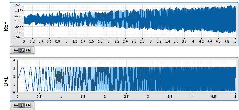
Quick background, I am in a position a signal with a ripple of mV ~ 10 with V 1.6 bias. I'm not interested in DC, only the AC signal but the NOR-9205 has only DC coupling. The application is a circuit where I expect simulations noise past the circuit must be greater than the higher noise frequencies. In the waveforms attached the background plot is the applied signal, and the top graph is the signal arising after that the signal was mostly annihilated. The two waveforms are measured with the NOR-9205.
I am aware that this measure is less than the precision of the NOR-9205, which has a maximum precision of ~ 3 mV in his +/-5V range. However, if I can't at least on the basis of shape which is good enough for me. I'm also now pretty curious that data acquisition is actually to create this
My best idea, is that it is a product of internal multiplexing of the 9205 with the DAC.
The first plot shows the waveform at 20 000 Hz, which is what I expected:
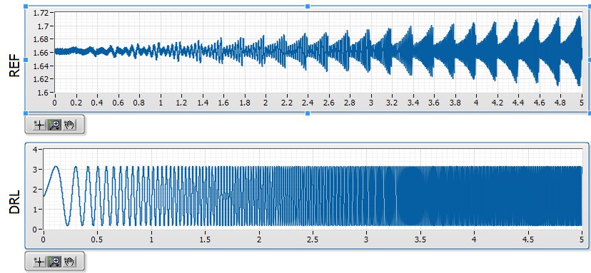
The second shows the waveform at 20 001 Hz, which seems to be modulated with a backup sawtooth:
The waveform looks as expected for 20 000, 20003, 20004, 20005, 20008, 20009, 20010 and Hz 20011. The waveform looks like modulated to 20001, 20002, 20006 and Hz 20007.
Ideally, I would like to understand this problem so that I can configure the measure in a stable way that I can count on the basic shape of the wave. Has anyone seen something similar?
-
Control and simulation and data acquisition
Hello
I am applying to motor control in Labview. I'm sampling speed from DC engine in real time through an acquisition of data. (my sampling time is 1000 samples per second)
Then wrap speed as input to a Simulation (simulation and design of the order) and inside the loop simulation, I have a PID controller. The PID has the actual speed of the engine for the acquisition of data and the engine reference speed as input.
Reference engine speed comes from the generator of signals (control design and simulation-Simulation) and is a waveform.
My step in the engine size is 1000.
I am running this application real-time and drawing the reference signal and the motor real signals. I run into several problems with regard to the calendar.
1. when I change the size of the step of the simulation loop, the frequency of squares of reference also seems to change. For example. What step size = 1000, duration of pulse = 1 s. What step size = 100, pulse width = 0.1. (My pulse frequency is 1 Hz, Simulation clock - 10 kHz). How step size can affect the pulse width.
2. can you explain the relationship between the DAQ, the Simulation step size loop sampling time, Loop Simulation period.
3. If I want to collect different sets of data using sampling different hours, it's OK to change the sampling DAQ time without changing the size of the step of the simulation.
Would also like to emphasize that the DAQmx calendar under sample clock mode is placed in front of the simulation loop and the output is connected to the loop simulation.
Appreciate any help.
Hello
Maybe some screenshots of your code would help. Furthermore, what you have read your samples together with your DAQ screws?
(1) If you have a waveform, the output is specified as:
For example, if you change the size of the step of the simulation loop, you change the simulation time which are introduced into the signal generator and affecting the waveform that you see if you do not have a size quite small step to characterize the waveform that you generate.
(2) sampling DAQ rate is the speed at which samples are taken on the acquisition of card data itself. The size of the simulation step, help. "Specifies the interval between the time when the ODE Solver evaluates the model and updates the results of the model, in a few seconds." Simulation loop, still using, "Indicates the amount of time that elapses between two subsequent iterations of the loop of control & Simulation.". " "Step size determine the value of t that is introduced to the functions you use in the loop simulation while the loop simulation period controls simply to how fast you change the following t value. The sampling rate of DAQ hardware is a clock of completely separate hardware controlling the analogue-digital on the DAQ card converter so that you can get a deterministic dt between the samples being acquired.
(3) you can change the schedule for the acquisition of data, but you will need to restart each time the changes take effect. If you change the calendar of data acquisition and want your values to correlate with your simulation, you will need to change your size of step as well.
-Zach
-Zach
-
Problem of reliability data acquisition PXI-4071
Hello
I'm having a problem of reliability using my 4071 Pxi digitizer mode.
I have a number of tests that use the SMU-6363 (usually configured for DC) analog output to provide a stimulus for our own device, which has a number of a/d converters. We use the PXI system for calibration and testing.
1. I select a voltage ranging from tensions.
2. program the PXI-6363 to drive this tension
3 TIME about 10ms to settle. Note there no discrete capacitors or resistors in the circuit. Everything is parasitic and would generally be under the nF mark and less than 10 ohms
3. configure and Initiate() acquisition of data with the PXI-4071. In general, I use a sample rate of 1000 s/s and get about 30 samples (worth 30 ms). Activation is immediate and I used the default a queue time, 0, set the time and it doesn't seem to make a difference.
4. measure the voltage with the CDA. For debugging purposes I have sometimes made twice once before calling Initiate() and once after. The after is normal. The time required to measure the ADC is shorter than the acquisition time, but regardless of stimulation by the SMU-6363 is constant
5. extract the waveform.
6. the average waveform and compare the value of ADC measured by applying tolerances etc.
Here's the problem: it works well most of the time. But only 0.1% of the time (1 on an acquisition of 1000), I get 8-12 samples that are close to 0. It sounds like a problem of time settling (on the surface), but no matter the amount of wait time data, I always get this behavior. Not only that, but the tension before the call to Initiate() in height CDA, it always confirms that the motor voltage is already set to the programmed value. Nevertheless the acquisition presents near data 0.
So far our independent ADC always reports the expected before and during acquisition (100%) voltage. It's like the DMM input is disconnected during the acquisition during a period of time, because we have confirmed that the voltage is already present prior to the acquisition (component can). I have no errors the insider or FetchWaveForm calls. I still have all my samples. And 99.9% of the time that everything works as expected.
The DMM and ADC are connected to the same point and both are referenced to ground, and as I said before only the parasitic capacitance and resistance (cable). We use a matrix of switching (PXI-2530 (b) to make these connections. We almost always use 51/2 digits and 10V range for data acquisition.
Hello
I thought about it and was going to repost but am distracted.
The device with the ADC also has a mux and switches the mux to an internal node. It only switches when measuring and is open at other times. There is a race condition where the acquisition starts too early and maintains the acquisition after that the switch is open. Unfortunately I don't have the option to trigger.
I forgot the internal mux that I had designed the test years ago and I did some updates to improve the stability of the test. That's why we start the ADC measurement when acquiring.
I just added a routine to reject samples below a threshold
-
Card FPGA and data acquisition synchronization
Hi, we are control and data acquisition of several hardware devices (including Photodetectors and translational stages). Until last week, we used all the controls and acquisition using a PCIe-7852R FPGA board. However, we decided to move the acquisition part to a PCIe 6363 DAQ card to improve the sharpness of the tension. During the test, I found that the internal clocks in the FPGA and the DAQ cards are slightly inconsistent (not just a phase delay, but a difference in the period).
I know because I have generated a square wave (period = 20) using the FPGA and gains using the data acquisition card (at a rate of 200 kHz, that is, 1 taste every 5). I have observed acquired place shifts 5 every 5 seconds approximately. Such a change does not occur if the production and acquisition is done using the same Board. Therefore, the only explanation is that the data acquisition and FPGA cards clock frequencies are different. According to my calculations, the percentage difference between their time clock must be 5/5 s = 0.0001%.
Therefore, I wonder if there is anyway to synchronize clocks between them. Or, is it possible that I can drive the FPGA clock-based DAQ hardware, or vice versa? Also, please let me know if there is something trivial as I fix.
Thank you very much.
Kind regards
Varun
Hi Varun,
my post was only one solution...
Your data acquisition card may take an entry to control sampling of trigger. In this mode, samples draw on a rising edge of the external clock signal. As long as you stay within the limits of the DAQ (100 MHz for your card) material sampling works perfectly. There are even examples coming with LabVIEW explaining how to program your data acquisition card...
This mode use you your FPGA as clock source sampling for data acquisition. Both will run on the FPGA clock in sync. When the FPGA is a bit out of 40 MHz, so it won't matter because both devices are triggered on the same clock signal...
-
extend the display time in data acquisition for more than 10 sec
I have create a vi of analog data acquisition. Everything works fine. However, no matter what I increase sampling # and rates; maximum display time is always 10 sec. I need to display the longer period time, but don't know how. Can anyone help?
Not a good VI. Where did you go?
The properties VI/execution has the checkbox next to unchecked the Autmatic error handling. And you don't have an error on your DAQ assistant indicator, or sons of the error at all. Fix them, and I bet you will see that you got a timeout error. Also, the while loop had uncontrolled Autogrow which means Add constants or change the display of the Express VI to disappear outside of the loop rather than more and more to their housing.
You do not have a timeout constant cable to the DAQ assistant, which means that it will use its default value of 10 seconds. This will cause a time-out error that you won't see because the VI property is unchecked and you don't have another handling error in its place.
-
Data acquisition reading incorrect when you use a loop
Hello
I wrote a simple VI (00, 01, 10, and 11) output to a circuit connected with 4 resistors. Based on what value the ciruit receives, it passes current through a particular resistance. It is again entered in Labview and traced.
The problem is when I send a particular value (i.e the 00, 01 and 10 and 11) and get that back, it's okay. But when I send and receive the consectively connected via the loop counter, they are incorrect (not synchronized with the number of the loop).
I made sure that circuit works very well. It has something to do with the loop synnchronization, reset, value compensation, etc. can be.
Please Guide...
Change your DAQ assistant that reads to be 1 sample on request.
Right now it is set for continuous samples. And 10 samples at 10 Hz. Then it runs and starts. The next iteration, you send a new digital out, but the wait for 4 seconds. When you read again, you get the next 10 samples that are put into the buffer of data acquisition, but now 40 samples have actually entered the DAQ buffer. In time your DAQ buffer will be finally complete and raise an error. In the meantime, you will continually read data continues to become more tainted by the iteration.
-
Data acquisition on OR sbRIO 9636
Hello! I'm working on my school project and I do the acquisition on OR sbRIO-9636. How I choose the sampling of acquisition period? I work as an example on the Web site OR below:
http://www.NI.com/Tutorial/4534/en/
I can't understand it on what sampling period should I put in Host.vi and in Target.vi in order to have the good acquisition? For an example, I would like to have period milliseconds 10 sampling. The configuration of loop-time in Host.vi and how Target.vi?
Thank you
Chupka,
Yes, the calculation of sampling looks good
this way, find all your data every loop, but you want to make sure you have a case to avoid FIFO overflows if you read each data point. With regard to the loop of the host, you do not want make sure that it is superior to the host loop so that if you encounter the jig in your curls, you won't have the time. -
DSA maxing out CPU data acquisition
I'm developing an application on a PXI-8196 (Windows XP) controller that uses a card PXI - 4472 DSA to read a single microphone and a FFT signal analysis. I need solve the two frequencies of 36kHz (and), so I've planned for sampling 96 kech. / s. I wrote a simple loop of data acquisition, configuring NI44xx DAQ/read screws using read the string unique at this rate, but when I run it, it immediately pegs my CPU 100% usage. So far, I did have problems with missing samples or the system crashes, but I am a little concerned that only data acquisition uses all my CPU time. Y at - it tricks that I can implement to reduce the CPU load?
I tried to vary the parameter samples per channel - with sizes ranging from 1000 to 48000 samples - buffer but I do not seem likely to reduce the CPU usage. Changing the sampling frequency affects the CPU usage (up to about 40% to 48 ksps / s; ~ 75% 72 ksps / s), though. According to this KB: http://digital.ni.com/public.nsf/allkb/D9DDF9FA02D1C18A86256EBC0016C93D
"A controller Embedded PXI-8176 can compute all the time of the spectra of FFT power on 8 channels for PXI-4472 clocked at 102.4 ksps / s »
so I think with my 8196 I should have no problem at all to read only one channel 96 kech. / s.
Anyone have any suggestions to reduce my CPU Overload? Thank you!
Here is a link to some good information on how to OR-DAQmx 7.4 and later behaves with respect to the use of the processor: Default CPU use with NOR-DAQmx Version 7.4
-
How to measure the angular velocity, the angle and trigger using a gyroscopic sensor breakout board and LabView data acquisition?
There is a single channel data acquisition code which measures the angular velocity, angle and flexibility using a gyroscopic sensor breakout board and acquisition of LabView data attached to this, I need a help to creat two-channel data acquisition code?
Hello
Attached is a vi that you can use in order to read the measured angular position of an encoder.
If you need more examples on the tasks that you can develop with NOR-DAQmx and LabVIEW, you just need to open LabVIEW and click Help > find examples > Input and Output material > DAQmx > entry counter.
Kind regards
-
data acquisition stops automatically
I want to stop assistant DAQ automatically after a period of time, so I created this VI.
When I start the program, it work and after reaching the value of time specific 50, the graphical indicator ' looks like "stop, but wait after 9999 second, the graphical indicator suddenly see a lot of data that seems to be taken for the 9999 seconds, what is happening? After that, it gives an error saying:
Possible reasons:
Attempted to read samples that are no longer available. The requested sample was already available, but has since been replaced.
Increase in the size of buffer, most frequently the reading of data or by specifying a fixed number of samples to read instead of reading all available samples would correct the problem.
Property: RelativeTo
Corresponding value: current playback Position
Property: Offset
Corresponding value: 0Task name: _unnamedTask<100>
Data acquisition cannot be stopped like that?

Thank you
Not quite. Like this.


Maybe you are looking for
-
MacOS Sierra of misreporting of space available?
After the upgrade to Sierra I noticed that the free space on my hard drive went to 63GB, according to Finder. However, when I try to copy a file 43 GB hard disk, I get the error message that there is not enough space. I tried to restart, but to no av
-
SQL CE sync error, internal error: the message of removal for the server was not created.
Hi all The error displayed in the synchronization history in replication monitor window. What is the root cause of this error? And how to fix it or avoid it? Thank you.
-
The lights blink and the error error message: 0x887dd03a
I have a printer all-in-One of 2600. At random, all the control panel lights will be flashing quickly, and display "blue out" and read only this error message "error: 0x887dd03a. I can always print, scan or copy with the printer, if I hit the power
-
Have Windows 7 Digital River to download after installing the drivers how much I'll have to find?
Having problems with my copy of OEM Windows 7 Home Premium 64-bit. Downloaded from Digital River and installation plan using my OEM license. My question is how many drivers I will have to find to install this? Thank you.
-
HP photosmart 7550 is not supported by windows 8 set now
can't get the driver for hp photosmart 7550 for window 8 the hp scan does not recognize the printer