Period with external clock measurement
Hello
I have the USB-6210 and I'm using Labview 8.0.
I use the 6210 for period measurement of a signal. I have another card (not OR) I want to synchronize with the 6210. The other card has a clock of 10 MHz with a TTL output.
I am trying to use the 10 MHz TTL of the other card as an external clock for my measurements (this would essentially be synchronize both). The measure of the time does not support external clocks. I can't make the edges of the county if not work. Any suggestions? Is it possible to sync the 2 cards? If this is not the case, what are my options?
Thank you very much
Eyal
Hi Eyal,
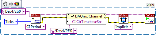
How did you get your task configured? It should look like this:
Best regards
Tags: NI Hardware
Similar Questions
-
Increase in the rate of sampling with external clock
Hi all
I have hardware DAQ-SMU-6361 and SMU-8360 controller in an express chassis SMU-1071. My 6361 maximum sampling frequency is 2 MECH. / s. But I want to use my daq with higher sampling rates. After going through the various positions, I decided for two options to increase my sampling rate. You must connect a 5 MHz signal generator to use as an external clock. Another is to use the timer to synchronize PXI Chassis
My question is
(1) what is the limit to the frequency that we can use as external clock for data acquisition? Which parameter is limiting the performance of the ADC, if we use the higher clock frequency signal?
(2) I also learned about an option called 'base time in PXI Express chassis'. can I use this option? Someone please give me a link to a good tutorial on the basis of time in a single PXI Express chassis?
(3) SMU-1071 chasis, 100 MHz differential clock. Is it possible to use it as a clock to my DAQ 6361 signal?
Concerning
Vaidhin.
HI Vaidhin,
The article mentions the background basket clock as a possible means for synchronization, but this is accomplished using it as a phase reference clock - align the oscillators on board your hardware DAQ which are then distributed down to produce the sample clock. You may not use background basket clock or time base on board directly as a sample clock (on the one hand, these signals is much too fast).
Measuring 1 MHz with a DAQ hardware 2 MHz could not give you what you expect. You will get 2 points per period of your entry - it's just at the limit to avoid aliasing of your signal and of course do not a good characterization of the shape of your signal. You might be able to push the card in slightly beyond 2 MHz but not significantly enough to make a huge difference. You are right that if you have sounds at higher frequencies could be an alias down in your signal. Any noise above ~1.7 MHz will begin to be eased by a bandwidth limited the 6163 (there is a chart in the specifications , showing the bandwidth). If you have between 1 MHz (signal) and ~1.7 MHz noise, you might look into an external filter, but again you are always sampling very slowly to be able to characterize the shape of the signal.
The next steps to the top (in terms of sampling frequency) would be as follows:
4 MHz: SMU-6124
10 MHz: PXI-6115
There are currently no products that use the same DAQmx driver who can enjoy beyond 10 MHz, but NEITHER there also a range of scanners that you may enjoy a lot faster. If you are interested in sampling up to 100 MHz, you may consider looking in the SMU-5122- there are also faster scanners available, but these are probably not necessary for your application.
Best regards
-
Hello
I use the card PCI-6111.
I am trying to acquire analog data on channels dev1/ai0 ai1/dev1 using pulses of external clock connected to the PFI0 channel. I also want to trigger the acquisition, when the channel dev1/ai1 signal reaches certain level. I send a triangle wave channel dev1/ai1, and I need the data only for the front.
I have configured the task in the following ways:


However, I get the error-89137 after function DAQmx Start Task:
Specified route can not be satisfied, because it requires resources that are currently in use by another route.
Source device: Dev1
Terminal of source: PFI0InputLockOut
Target unit: Dev1
Destination terminal: AnalogComparisonEventResources in use by
Task name: _unnamedTask
Source device: Dev1
Terminal of source: PFI0
Target unit: Dev1
Destination terminal: AI/SampleClockTask name: _unnamedTask
If I change the internal clock external clock - switch works. If I pull the trigger, the external clock works, too. But these two tasks do not work together.
Help? Advice? Thank you!
-
Alrighty, I'm a total noob to LabView and others. I'm at the point where I don't even know if I know is relevant, so forgive if I give too much information and probably not enough.
I've got:
cDAQ-9174 chassis
9422 module into the connector #2
This 9422 module will be connected to a meter that will send a square wave. What I need is the frequency of the square wave. Problem is, I don't have any idea how to get it.
I open a new .vi and use the DAQassist. From there I select entry counter and then I tried the frequencies and Edge Count.
At the end of the day, either it usually gets me the following error message:
Error-200284 occurred to...
Possible reasons:
Some or all of the requested samples are not yet acquired.I guess that one I did most of the research is the counting of edge. It is continuous samples because I need to monitor the flow rate at the time rather than only to count the edges of time 0 until I stop the VI. So there are different ways to treat this error include changing the timeout value, something to do with 'samples to read' and 'sample rate', and then that it seems to me that I have to do: since the buffered continuous one requires an external clock, which is specified in the tab "Advanced Timing" of the menu properties DAQassist I have a lot of things to choose from. It seems/I/SampleClock or/ao/SampleClock is the thing to choose, but then several Web pages continue to say to make sure that the external clock is actually "run", or any word in this sense. So I tell myself, my external clock isn't doing anything and that's why reading isn't acquire samples. But really, I'm just lost. Then...
Question 1:
Is what I'm working on the best/right way to go about doing this?
Question 2:
How can ensure me that this external clock done everything what it is supposed to do so that I can get samples still for edge counting?
Well, my ignorance is exposed, please fire away. I have attached the .vi, although I don't think it will tell you anything other than I know how to click the mouse button when running LabView.
County Board is time since you don't have a sample clock. You can provide one from many sources, but in your case I suggest sticking to a task of frequency measurement I won't go into it now.
The frequency could be time for a number of possible reasons:
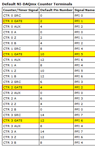
1. the external signal is not connected to the right Terminal (the default IS terminal your meter chosen if you not him have not overridden with a property DAQmx node which is not possible in the DAQ Assistant). For the 9422:
2. the signal may be connected to the right Terminal, but perhaps, it does not meet the specifications of the 9422 to be detected)<5V low,="" 11-60v="" high).="" you="" can="" verify="" whether="" or="" not="" the="" signal="" is="" being="" detected="" using="" a="" test="" panel="" (counter="" edge="" counting="" to="" determine="" if="" the="" signal="" is="" present)="" in="" measurement="" and="" automation="">
3 tasks of frequency are sampled off the input signal - so if the input signal does not switch when you start the program or if there is a long break (longer), you will receive the time-out error when the reading function blocks for more than your specified time-out. You should be able to just 'manage' the time-out error so that if it happens you can report a frequency of 0, ignore the error and try to read it again. There are also other approaches such as using events DAQmx or samples available to read to vote, but none of them are available through the DAQ Assistant (the idea is that you avoid making DAQmx Read blocking call until you know there are samples to read).
Configure a task of frequency is a better option for you, because it will give more precise (although you can set a task of County of edge to behave similarly to a frequency measurement task, this is trickier and you can also use the DAQ assistant). You can start out by setting 1 sample (on request) for the synchronization mode - this will return a single sample as soon as it is available. If you put the DAQ Assistant, in a loop, you will get a new sample at each iteration (or if your input signal goes, the samples will stop coming in and you'll get time-out errors instead). The downside is that you will not receive a sample on each side - entry task is reset by software and during this downtime between the samples will take no new data. This should be good for the case of the use you described (the frequency of a continuous square wave periodically monitoring).
So, make sure that the external signal conforms to the specifications of the 9422, and it is connected to the correct terminal (the PFI line which is equivalent to the DOOR of your meter by default). If your external signal is less than 0.2 Hz (1 sample every 5 seconds) you will need to move away from the DAQ assistant, as it seems that it is not possible to set the timeout of read using the DAQ Assistant (surprisingly). You might want to look in the API of DAQmx lower level anyway - here is a simple example to help you get started in the affirmative. It's really not too complicated and once you get used to it will be less heavy than using the DAQ Assistant.
Best regards
-
HSDIO 6556 loses the lock on the external clock
Hello
I'm encountring a strange problem. I use my 6556 HSDIO to generate some model using and external clock (around 20 MHz and 50 ohms impedance). This clock is provided by an MCU and the entire application does not work well. However, when I tried to cool the MCU (up to-10 °) the HSDIO loses the lock and tries to re - lock again (the Red turned led active). When this happens, I can see a new phase shift between the data generated and the external clock, within the scope that is fatal for my application. L ' other, I inspected the data generated looking for a glitch or gigue appearing at low temperatures... Notice anything special... I tried to heat the MCU upward at 100 °, HSDIO does not lock...
What can I do? 6556 HSDIO is apparently too sensitive...
Mar1
Hi Mar1,
Datasheet public for the chip used in the States of SMU - overclocking 6556 a typical tolerance of jitter of 20 000 ppm, with minimum of 5,000 ppm. For a 20 MHz clock, this corresponds to 1 ns of jitter typical and 250 ps in the worst case. That being said, we cannot guarantee the specifications that are not included in the specifications NEITHER SMU-6555/6556 document because it is not updated with the production trial.
Best regards
-
external clock or wave pulse or sinusodial?
Hello
I'll plug an external clock to 6711 map source. But I wonder if the source should be trains of pulses (wave squre) or it might be vague sinusodial. When we say the frequency of the clock, it means the occurrence of the rising or falling on board but not the pulse, right? And what is the range of voltage for the clock signal?
Hi dragondriver
The external clock should be a pulse train, not a sine wave.
When we talk about frequency, as you said that it: the appearance of rising or falling edges within a period determined.
Voltage range must be from 0 to 5V.
Concerning
-
To use the external clock for SCTL myRIO
Hi people,
I'm trying to find a way to get a 2.5 PSM 16-bit ADC, TI ADS1602, to send data to the device myRIO. Ideally, I'd like to bit Records at 40 MHz in order to obtain the benefit of the PSM full 2.5. I know that I can create an 80 MHz SCTL on the FPGA to create a clock of 40 MHz, but when I checked the clock on an oscilloscope signal, it was obviously greatly degraded by bunch speed limits, so he looked more like a sine wave to a square wave. I doubt it would work for use as a clock signal to drive the ADC since ADC specifications say that eligible jitter is around 100ps.
I can use an external oscillator to drive the ADC, but then I have to find a way to sync the clock with clock FPGA 40 MHz. is there any kind of PLL structure that would allow me to sync the clock FPGA myRIO to an external clock? Is there a way to do a loop simple timed cycle driven by an external clock? Or if I was able to customize the FPGA personality to accept a SPI signal up to 40 MHz (ten times her supported limit...), he would be allowed to use an FPGA to ~ 160 MHz and tell him to taste the SPI line each loop and proceed from there?
Thank you!
Hi 3.14159... ,
The myRIO doesn't have the ability to import a clock to use on the FPGA block diagram for clock loops timed cycle unique (SCTLs). The sbRIO-9651 new coming out week OR (not shipping yet) is the only sbRIO who has the ability to import an external clock in LabVIEW. Many of our products FlexRIO also have this ability.
Like you we have it, you can taste the signal at twice the frequency (or maybe more) to and wait an edge trigger to run a certain element of logic. "" "If you open the example Finder and navigate to hardware input and output" R series "FPGA Fundamentals ' triggers and guard dog" trigger detection, this gives a simple example to do this. Once again, since you are eager to taste 10 times the frequency of support, all bets are off, but it may be worth trying.
-
FPGA and external clock Source
By using a PXI-7854R, is it possible to run a process on an external clock source? As far as I know, you could potentially bringing the external clock to one of the triggering RTSI lines. Is this correct? Is it possible to route through one of the connectors on the PXI-7854R? If this isn't the case, I also have a PXI-6229. Can the external clock be routed to the RTSI through the PXI-6229 and then line for the PXI-7854R to run the process?
Hello
Unfortunately not, as noted hereand here. The best solution is just the external clock with DIO on a structure of case to door. While this will not have any type of phase synchronization and you may miss the clock cycles depending on how long and how fast your external clock is running (not really an option). I hope that answers your question.
-
How the PFI to go top-to-bottom with sample clock?
Hello world!
I am very new to LabView and I try to do something very simple in the NI PCI-6534 and still not get anywhere (or do not know if it is the limitation of the hardware)
My request is to acquire digital data of 2 channels (16-bit each) of our Board custom designed analog-to-digital.
So far, I am in a position to acquire a finite amount of sampling digital (say 100000) and using a trigger to start (PFI6) to start the acquisition of our custom card board. Just to let you know that I'm feeding the PCI-6534 an external clock of 20 MHz by PFI2.
However, I want to send a signal to trigger recognition (high/low-rising edge) to our personal advice, saying: he did the acquisition of 100000-sample.
My problem is that whenever I try to use the lines of PFI signal with an internal sample clock, I get an error saying that I can't use the PFI lines with any sample clock. But my goal is to use a rising edge (low-high) to trigger back.
So far, I can pull the PFI4 high and used a timer to make it low. But the resolution of the timer is milliseconds (software) range. I would like to have at least a few microseconds.
I also tried using implicit since manual said that it does not require any clock but still get no result. Also, I couldn't find an example of implied clock and don't know if PCI-6534 supports.
Note that I'm able to use the clock synchronization of sampling with other DIO (Port 0 to Port 3) lines and get the result I want. However, I would need to use all our custom Board 32 - DIO for analog-to-digital data lines. So, using the line of PFI laccuse is the only choice.
If you have ideas/pointers, please throw it at me, I'll try them. Thanks a lot for your help!

See you soon,.
Yaseen KhanHi ykhan,
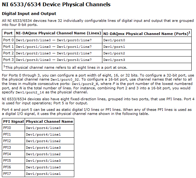
After validation, I noticed that it will not really work for what you are trying to do. The PFI lines on your 6534 are I/O static only as shown in the DAQmx help.
You will be able to control these lines, but only with software timing. You should be able to call and argue by their physical channel name. I hope this helps!
Kind regards
-
Reading and samples the sampling frequency using a fast external clock
Hello
I use an NI USB-6212 box to launch a search engine for combustion. I have a pressure sensor in the head and a wheel on the crankshaft. I use the beats A Quad channel of the rotary encoder as a sample external to the pressure with the sample clock. The idea is that I want almost the same number of points in each trace of pressure so that it is easy to average together. I seem to be able to do this at low speed, but I'm having issues at high speed.
Can someone tell me what I should have my sampling rate and samples to read together and how it effects my sampling when using an external clock? Samples per channel will affect the size of buffer and that matters? When I was high (10-100 kHz and about 1/10 * rate for samples to read) it barely read but as I put the lowest and lowest he read faster. Play with the settings a bit seem to affect how well it samples at different speeds. The engine is running at 3600 rpm and my encoder puts out 2500 pulses per turn on one channel, I'm looking at a frequency of 150 kHz effective sampling. However I didn't sample program with the engine operating at full throttle. I hung on the output of the encoder up to a scope and reads very well.
Are there opportunities the filter counter that I see in the manual of 621 x is enabled inadvertently?
Thank you
Xander
Xander18,
I suggest you move your screws initialization outside the while loop, as well as your narrow DAQmx VI. On my side, it looks like a new task is performed for each loop, which takes time. That a try and let me know how it goes.
-
I have an external clock 20 MHz connected to APFI1, I want to use as a sample of 16 clock inputs digital. Unfortunately I wanted to divide this clock by 2 at the hardware level, but I forgot in the mad rush to get out the Board. Now I find myself with a problem! Map NIDAQ I use (NOR-6289) can enjoy digital inputs as soon as 10 MHz so just sampling and decimating in the software is not an option. In addition, it seems that counters cannot treat ticks is less than 2, so low, I can divide the external clock down by 4. The only option I see at this point is to use the external clock as a trigger for a free counter running on the clock of 80 MHz. The counter would then serve as clock for digital inputs. However, I want to retain the flexibility to change the external clock and not constrained by the software.
I was encouraged at the beginning of this thread, but unfortunately it does not seem possible with digital inputs.
Y at - it anyway to divide this by 2 clock and use it for digital inputs?
Thank you
Drew
Hi Drew,
I think you can probably find this works using an output meter task set to pulse Mode instead of toggle (default). Here is an example that shows how to configure the meter in this way. I have posted just the example, you may need to wait a few moments before the transfer is completed.
Best regards
-
How to read multiple channels based on the external clock
Hello
Normal 0 false false false MicrosoftInternetExplorer4 / * Style Definitions * / table. MsoNormalTable {mso-style-name: "Table Normal" "; mso-knew-rowband-size: 0; mso-knew-colband-size: 0; mso-style - noshow:yes; mso-style-parent:" ";" mso-padding-alt: 0 to 5.4pt 0 to 5.4pt; mso-para-margin: 0; mso-para-margin-bottom: .0001pt; mso-pagination: widow-orphan; do-size: 10.0pt; do-family: "Times New Roman"; mso-ansi-language: #0400; mso-fareast-language: #0400; mso-bidi-language: #0400 ;} "}
I use 6254 multifunction for playback of tension with VC ++ 6 as the development tool.
Based on the documentation NOR I created tasks like this.
DAQmxCreateTask (_T ("Voltagetask"), & taskHandle);
DAQmxCreateAIVoltageChan(taskHandle,sChannels,,DAQmx_Val_NRSE,0,10,DAQmx_Val_Volts,);
DAQmxCfgDigEdgeStartTrig (taskHandle, "PFI2", DAQmx_Val_Rising);
DAQmxCfgSampClkTiming(taskHandle,"PFI2",303000,DAQmx_Val_Falling,DAQmx_Val_FiniteSamps,nSamples);
DAQmxStartTask (taskHandle);
After the generation of clock finished thanks to the DAQmxReadAnalogF64 function, I tried to read samples of each channel.
DAQmxReadAnalogF64 (taskHandle, DAQmx_Val_Auto, 10, DAQmx_Val_GroupByScanNumber, read, m_nStates & sampsPerChanRead, NULL);
Total number of samples (nSamples) available in the buffer when the task is created with a single channel and several channels are still to come as even. In several modes of channel returns total sample by channel, which is equal to the total number of samples divided by the number of channels at once.
For example, if a total number of clock 8000
With single channel, it reads all the 8000 samples (m_nStates = 8000, sampsPerChanRead = 8000)
When two tracks he read 4000 samples per channel and so on. (m_nStates = 8000, sampsPerChanRead = 4000)
If any body know, on every clock how to take samples of all of the configured channels.
Thanks in advance,
Renjith.
Renjith,
Please note that the behavior, I explained is in line with the provisions should only if you use your clock as I convert clock. You can find information about the different types of synchronization of the analog inputs using NOR-DAQmx; the element to search for is "clocks".
Since you do not set the clock to convert MY (should be DAQmxSetAIConvSrc()), the fact that I mentioned above is only informative for you, but does not apply to your question. Sorry for responding too quickly without looking in your code between quotes...
In order to answer your question, we take a look at the approach to programming DAQmx:
If you configure your task to be "finished", the task will stop running if the number of samples per channel is acquired. In the case of an external clock (not configured as I convert clock), served it in the sampling interval. The sample clock will automatically receive a sample for all channels with a single clock pulse. From this point of view, the installation program you have in your program seems correct.
If you do not get the number of samples that await, the fault must be somewhere in your playback function. Do you get any error messages?
DAQmxReadAnalogF64 (taskHandle, DAQmx_Val_Auto, 10, DAQmx_Val_GroupByScanNumber, read, m_nStates & sampsPerChanRead, NULL)
If you set m_nStates set to 8000, it's here. You say the Read function to retrieve 8000 samples. None. So if you have two channels, DAQmx acquires 2 x 8000 samples, but read you only 8000 samples... Please change m_nStates to
m_nStates = #channels x #samples by channel
This should solve your problem.
hope this helps,
Norbert
-
Are there any known problems with external battery for iPhone 6 s karim?
Are there any known problems with external battery for iPhone 6 s karim? Jackery of input: 5V / 2. 1a.
I had heard that some may damage internal parts of the phone.
I am interested in what Apple says rather than what says karim.
Thank you.
Jkim99 wrote:
Are there any known problems with external battery for iPhone 6 s karim? Jackery of input: 5V / 2. 1a.
I had heard that some may damage internal parts of the phone.
I am interested what said Apple rather than what it says karim.
Thank you.
There is no Apple here in this technical forum from user to user.
-
Portege M200 with external monitor - what is the best resolution?
As a result of a recent post on using an external monitor with the M400, I have a question on the use of one with the M200. I realize that the M200 uses the graphics card Nvidia rather than the graphics card Intel in the M400 - is it better with regard to the use of an external display is concerned? The M200 manual says that it will support up to 1600 x 1536 resolution on an external display. I want to use my M200 in a docking station with an external monitor to the extended desktop.
What would be the best resolution to go with externally? Should I go for 1400 x 1050 screen LCD M200 match? Or could I go for a 1600 x 1200, that should the graphics card (!) be able to cope? Or, finally, if I went to a widescreen 1680 x 1050, how would the face Nvidia card? The screen is not as clear as with the 1600 x 1050 screen?
What are the chances of work at all? I see in the M400 manual which she is supposed to support 2048 x 1536 on an external monitor, but this seems to be a problem, judging from the other post.
Any help appreciated - thanks
Hello
Well, the resolution of the screen depends primarily on the graphics card.
If you want to use a display resolution that the graphics card must support. In addition, the graphics card driver is important. If the graphics card will support the resolution of the screen, BUT the resolution is not listed in the graphics driver, so you will not be able to choose this value.To my knowledge, if you use the docking station you will get Supportepar as the notebook display resolutions.
The resolution of the external display also depends on the external display. If the material of the monitor will not support the resolution so you will not be able to get all the images on the external monitor.I think the best way is to test that the resolution is the best. Some people prefer the high resolution of small icons and other blind ;) like low resolutions (1024 x 768) because of the large icons
-
Portege M200 with external DVD drive
I have a M200 with external drive DVD COMBO Slimline PX1055E-1NST.
I've upgraded to VISTA and it will reinstall the devicedriver. Where can I find a driver that works with VISTA?Hello
Your player is connected to the PCMCIA slot. Am I wrong?
Unfortunately, at the moment that these drivers don't exist! :(
I didn t find on the page of the Toshiba driver.Try searching for any 3rd-party PCMCIA drivers for Vista. Maybe you're lucky.
Maybe you are looking for
-
Satellite A210-171 - new graphics card update
Currently, I have a toshiba satellite A210-171 with an ATI Radeon® X 1200 graphics card.Mass effect on the laptop, I installed and I can't play it because my graphics card is good enough, I was just wondering if anyone knew a graphics card which i ca
-
How to export to pdf 1 sheet in a document with multiple sheets
As the title says, my numbers document has several sheets. I need to export one of these sheets as a pdf document, but instead it exports all sheets in a single PDF with multiple pages (1 page per sheet). Grateful for your help!
-
Cancellation of a request for a refund
I ordered an item on my iPad from Udemy. The iPad repeated that its cancellation all the time so I used a problem report to request a refund. Not two minutes passed, and I got the price I had paid for. I do not want to cancel the request for reimburs
-
Are there 3 partitions in iconia W510 win 8, primary, restoration and mbr partitions?
Are there 3 partitions in iconia W510 win 8, primary, restoration and mbr partitions? I'm freezeups and other defects. I tried recovery and saw what looked like 3 partitions. tried to format the C: drive then tried to reload the dvd.still system's gl
-
Windows Vista Home Basic Edition does not detect networks wireless scope.
running Windows Vista Home Basic on my counter top and it will not locate wireless... period. I know at least 3 in the box and he is always telling me that there are no wireless networks detected. On a side note, I installed my router wireless on my