Analysis of the signal acquired permanently
I've got 2 acquired signals of a data acquisition with a swab sample set to 1. All my code is in a time loop. How would I go about to fill a table with x samples for digital analysis, then erase the old array to fill with newly acquired x samples? It is important to be able to do this analysis during live acquisition.
Nevermind, I figured it. I used the VI express Gate & trigger to get the recorded samples.
Tags: NI Software
Similar Questions
-
How to trace the signal acquired against the clock all the time fixed by using Graph XY?
Hello
My goal is to trace the signal acquired against the clock all the fixed time dynamically. In General, it is like trace the waveform of the signal against the clock in a graph, but don't keep the recent 10 min waveform. My current approach is to get the timestamp by a VI and the express VI to use XY graph to make the plot. The result keep all data in the history which is not what I want. My question is that how to achieve my goal?
Thank you very much
Hao
One way to show the last ten minutes of data is to use a graphic instead of a graph. Set the size of the history of the ranking for the number of samples you acquire in ten minutes.
If you want to use the graph XY, you will need to manipulate the data yourself. If you don't want data from the last ten minutes and you want to throw all the old data, set up a circular buffer sized to hold the ten minutes of data. Once the buffer is full (after the initial ten minute break) adding a data point removes the oldest point. Make the buffer of a 2D with X data table in a line and the data Y in the next line. A queue with loss can be used in recent versions of LV to implement a circular buffer. In older versions, a driving force would be a good choice.
Lynn
-
How to select the signals from the output of a DAQ assistant
Hello!
I am a new user of Labview 8.5 and I work with a USB-6210. I have two different instruments connected to the same USB device, half of the channels are used for the transducers of pressure where I only need reed and record data, while the other half are associated with TCD detectors where I need to perform an analysis of the signal to get and save the data. I'm in the first stage of construction the block diagram, once I have defined each of the signals that its correspondent of channel using the DAQ assistant, I need to select and separate the signals coming from sensors of pressure from those who come by the TCD detectors, before that I can continue to draw the block diagram. I am using the function select Signal, but I don't know how to do this. Can you get it someone please let me know at least in which manual, I can find a good explanation? I have read the getting started and the LabView user manual, but they have not been very helpful so far.
Thank you!
I fixed it. As you say, I had some mistakes in the thread, but it's working now. Thank you very much for your help! It was very useful.
-
Analysis of the order when there is a significant shift of DC signal
Thanks for reading this. I use the Toolkit NI LabVIEW Order Analysis for direct analysis of signals of pledge of deformation of an attachment to a car engine. My goal is to acquire data of a part of the calibrated strain connected to an engine during the rampup and identify the controls in the signal of the strain. I am not able to understand a problem I see with my results in the power of order spectrum.
I measure the signals of pledge of strain during the preparations for engine using the module 9235 cDAQ (1000 to 6000 RPM in 15 seconds). I also acquire the tachometer using the module NOR-9402 (counter). Then I converted the signals of the strain at the same angle signals and made the order power spectrum.
Please order power spectrum resulting Fig1 shows. What I find that is the DC offset in the signal of strain presents itself as a high amplitude (red or green) peaks in the power spectrum of order (see Fig 1) around the order of 0. Because of these enormous peaks around order 0, the peaks of the order of a real interest around 2 or 3 command (blue or purple) are difficult to discern in the graph.
The DC offset clearly shows the chart of strain vs RPM (RPM is a linear function of time), if necessary, it is identical to the strain vs time. The white line in figure 2 corresponds to the DC offset. In this example, the CC offset is constant during the rampup rpm, but more often, the party calibrated strain of experiences both change static and forced lengthening cyclic as in Fig. 3. Here the sudden part increases the deformation in traction, with cyclic constraint superimposed on top of that.
My questions are:
Am I missing a key here in preprocessing step?
-I need a high pass filter to remove DC offset?
Subtract the average value of the signal from the time signal based before sending to the treatment?
How does a handle signals that have a variable static elongation a cyclical signal above the static signal? This appears to me a common scenario in the measures of constraint because ESA undergoes two different static and dynamic constraints in a motor boat.
Thanks for your comments and advice!
You have several choices, depending on what you want to do.
If what you want is a nice parcel of land, and the DC signal not enough to affect your 1st order, then simply set the component continues to 0 once you analyze varies.
Presto - instant removal of DC. It is perfectly legitimate, as long as the domain controller is not wandering too. Mathematically, it is exactly the same as the withdrawal DC before analyzing. (an inverse THAT FFT of this result and you will get the signal without DC, if you don't believe me).
OR
You can do as Bob has suggested and take the average. If your length of block is short compared with the rate of change of the real continuous component, it is fine.
OR
You can remove the trend by interpolation. For example, for a block of 1024-pt, find the way to 100 points around (on each side of) the beginning of your block. Find the way to 100 points around (on each side of) the end of your block. Find an equation (Y = mX + B) to describe the trendline it and use this equation to subtract a different DC value for each point.
OR
You can remove the trend extrapolation and interpolation. For example, for a residence of 1024 pt. find the average of the first 100 points and the last 100 points and assign these values X = 50 and X = 973 (1023-50). Find an equation (Y = mX + B) to describe the trendline it and use this equation to subtract a different DC value for each point. You need to face the fact that X = 0 starts BEFORE your trend line at X = 50, but that is basic algebra.
Remove trendline technique is more accurate and necessary if the domain controller changes siugnificantly during your block.
-
How to acquire the signal to very high sampling frequency
Hello world
My name is Luke Ho. I am trying to acquire the signal with Labview (Sthelescope). The signal comes from sensor acoustics, then filters and amplifiers to adapt to ADC rank (0 - 5V). Thus, the maximum frequency of the signal is 40 kHz.
According to the Nyquist theorem, I sampled at least 80 Khz signal.
Is there a sampling frequency devices like that? or y at - it another way of better? I used the Arduino before, but it was about 10 kHz.
I need your advice.
Thank you all and have a nice day.holucbme wrote:
Thanks for your recommendation
But is it possible without USB Data Acquisition, it is quite expensive for me.
This is the cheapest option to NEITHER. I tried to look for options to other companies, but more I found in the same price range, or not answering is not your condition of sample rate.
-
I am facing a problem with the beep.vi. I have a DAQ program, which acquired the signal and compare it to a threshold value. When a signal is out of range, a Visual and sound alarm has occurred. I use the VI beep.vi to generate the sound. Everything works fine except the sound alarm. It gives the table 1 d of type mismatch. I tried to fix this by placing it in a box structure. But it still does not work. If someone could help? Please find attached my VI. Best wishes to all visitors to the Forums of Discussion OR.
Ihab El-Sayed
published here: http://forums.ni.com/t5/LabVIEW/Playing-sound-based-on-exceeding-a-threshold-value-1D-array-data/m-p...
-
Amplitude of the Signal after the FFT analysis
I'm currently trying to find the amplitude of a signal after running a FFT analysis. I use this for image analysis MTF. I take the profile of the line of fire (with an alternation of black and white bars) and convert it to a signal. This signal is then introduced to a FFT Mag/Phase VI extent and output of the FFT. My program then enter the amplitude to frequency of alternating black and white bars.
My problem is that the amplitude seems to be scaling by a factor. I would like to find the exact amplitude of the signal of my analysis. Anyone know the factor of scale or any problem with my program? I joined the program and the image that must be analyzed. Just browse to the image in the VI and run the program and you will see the MTF chart resulting.
Thank you
Ronak
-
FPGA acquires only the positive part of the signal
Hi all
I have the NI USB-7855R and using the personality of DAQ balanced example of e/s (http://www.ni.com/example/5961/en/). I plugged my generator Agilent to AI0 (in mode CSR) and I have the following problems:
(1) waveform graph in LabVIEW is only to show the positive part of the sine wave that I am providing to the Board of Directors (clipping at 0 V). Only by compensating the signal from the signal generator, I am able to get the two cycles.
(2) while I am out 5 Vpp on the generator of signals on the graph of a waveform in LabVIEW I see only 1.5 mVp.
Any suggestions on what could be the problem?
Thanks in advance or your help!
The first graph of "analog input" in your link shows the analog inputs are converted to unsigned integers (U32) before their passage in the FPGA-> host FIFO. Negative values will obviously be lost make this conversion.
-
Problems with signal followed during sampling of the signal
Hello
I'm relatively new to LabVIEW 8.0 and I'm having a problem with being able to monitor the signals that I am gaining two simultaneous analog signals. I have the user to input the frequency of sampling and the length of the sample, and then I starts the scan, but when running the analysis, I don't see no result on the chart if the duration of the sample is passed, at which point all data comes. Previously, I could see the acquisition of real-time data and I don't know what I've done since then have possibly that stop working. I tried to introduce a kind of late for may allow the software to apply the data to the graphics, but I had no success.
I have attached the VI of the data acquisition component.
Thank you so much for reading this.
Hello
I suggest you try these two options:
1. in each iteration of the while loop, add your data to the data of the previous iteration, IE use a shift register to create an Adrien to data that you have acquired. When you save the data in a file, read data from the table and not the current value of the waveform. You can read the data in the table by using a queue, or by using any simple method to pass data between the blocks.
When you use a local variable of the waveform card, you only read the current value in the array, not its history.
2. use a property of waveform graphs node to read the history of the ranking, convert the picture from picture to picture 1 d 2D using cluster of waveform ungroup functions and write to the file, click on "Save".
-
Have signal via Qosmio player, but failed to retrieve the signal on WMC
I have to be halfway there, but after connecting my NTL cable box to the Qosmio and who received advice to get my signal through the reader and the F2 key, I can't then the signal in Windows Media Center.
As I am only interested in recording TV shows, I really need find a signal through WMC. Please can someone help I think I ever recover calls promised from the technical support line. Oh, I followed all the instructions, but the analysis through Windows Media Center does not give any signal.
ADMISI,
Exactly how do you connect your NTL cable box to your Qosmio?
Willow
-
Digitization and adaptation of impedance of the signal source entries
I'm trying to measure the voltage difference and the time between the two entrances of a USB-5132 digitizer. The switching interval that I try to capture is ~ 150uS and I intend to acquire ~ 25K samples (50MS/s for 500, although it is an overdose of sampling frequency). The digitizer is 1 M ohms entered and I wanted to use the 100 SMA 50 ohm cables to connect to the source of the signals which in addition to several kohm impedance. My knowledge of RF is low and I am concerned about the impedance matching between the digitizer inputs, impedance source and wiring. What kind of considerations to I need to avoid degrading the signal? The switching signal is pulse-like and is rich in harmonics and on a sample of 500K samples/s scope is represented accurately. Should what kind of considerations I do about the impedance?
Hi William,.
There will be some problems if you try to use a source that has an impedance of several kohms. You will probably get the reflections of signals. What is the source of your signal has several kohm impedance? I'd take a peek through the following article Developer area that describes some of the considerations when it comes from impedance matching. Specifically, I would check the last section corresponding resistive. This should give you a better idea of what to worry about your application.
http://zone.NI.com/DevZone/CDA/tut/p/ID/3475#toc4
Here are also a couple more developer area articles that you might be interested in what concerns your situation.
http://zone.NI.com/DevZone/CDA/tut/p/ID/5779
http://zone.NI.com/DevZone/CDA/tut/p/ID/2892
Chris W
-
Display or process the data acquired by NI 5732
Hi all
I have a scanner high-speed NI 5732 works with NI SMU 7962R. I need to acquire data at high frequency and the process/view it online if possible. I think the problem is that the while loop in the high acceptance of the VI page is too slow to read the data sent by the FPGA. I can see clealy waveform when the input frequency is low, but when the frequency is high the ugly looks of waveform. Is there a way I can see the waveform clealy high frequency in real time? Or I can use somethig like a FIFO to store data and view it later?
Thank you
Tong
Hi Matthew,
Thank you for your answer and I've already found the solution by myself.
I did the FPGA and host screws by myself according to the example of "Getting started". I use the internal clock of 80 MHz in the FPGA VI. I'm trying to use NI 5732 to acquire the signal with a frequency of several MHz, so I think that the acquisition rate is fast enough.
I solved the problem by using a target-to-host FIFO. The maximum size of the FIFO seemed to be 32767, so I put this value. Also, host VI, I put the number of items to be read from the FIFO to 10000. So I can view the MHz signal at the host VI.
Best,
Tong
-
Why the signal are seen in the way IQ?
Hello world:
I'm confused on a phenomenon I have seen since a simple demo. The demo is that a sinusoidal signal is transmitted by the USRP by I traced. I have observed sine signal to two I have paths and Q of the signal for the same USRP. Signal path Q is not smooth like the I traced and the amplitude is lower. However, I think that the Q path should not exsist signal. I understand this problem as shown in the figure and the attachment is the demo
The USRP allows Tx and Rx LO are independent with a common reference, allowing you to tune in at two frequencies at the same time. It also means the phase of are of two different LO. This means that the acquired signal scatter energy between I and Q, but will have a common complex amplitude. If the traces on a constellation diagram, what it would look like a rotated constellation.
-
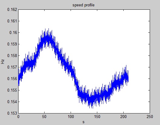
Analysis of the order - the speed profile of the data measured in Hz
Hello
When I want an analysis of order in LV, I need to have the tacho signal. I understand that I need a certain signal "TTL" where there's one pulse per turn. ___ |-| ___ |-| ___ |-| _ The period depends on the rotation speed. This signal is transformed into BT on the corner same signal and the output is signal of speed profile that will at OA blok.
However I my case I don't have the TTL of tacho signal but turn signal speed in Hz and corresponding to time values.
I know that speed is about 0.1-0.2 Hz I have 200 seconds the signal with 4000 samples of rot. Speed in Hz and corresponding to time values. I want to do the speed profile cluster that contains the time table and table RPM. My idea is to just take the time and decay values. Speed in Hz multiplied by 60 to get the RPM.
However, I am not sure about this. OSTEOARTHRITIS results seems not to be correct. Some does something like that?
Try the attached VI. There are two matrices of equal size, speed in rpm and the timestamp of the control system. It produces a continuous-time waveform that can be used with analog tachometer VI of analytical tools of enforcement.
-
Hello
Im trying to understand our noise of a laser. My setup is Laser - detector-Oscilloscope. I read the signal using a GPIB and Labview program. I think that I must take the FFT of the signal produced but it gives me nothing. I plugged the output signal to the FFT.vi and the result is a peak at 0 (zero). I should al least see peak around 60 Hz (light), but I can't. My sampling rate is 100Ksamples per second. Also, how can I see frequency on the x-axis of the curve of the FFT and what is Y Chart FFT plot?
Thank you
Yes. Without information from dt, spectral analysis function will assume a sample rate of 1.
Maybe you are looking for
-
Color HP LaserJet Pro 200 M251nw to print alignment
Images and text color print out of alignment. The problem started the first day that we had the impression. It took me a while to get into this diagnosis, but I tried the following: I tried to replace the (expensive) with new toner cartridges. The
-
I just bought this printer last night. I'll order a laptop with windows 10. This printer is compatible?
-
I have windows 7 I can go ahead and download windows 10
I have windows 7 and I can support windows 10 with window 7 always on labtop
-
What programming language windows use
programming language windows operating systems use windiws 7, xp, 8 written in what language
-
Windows 7 pro. Two characters rubbed off during shipping. Cannot complete the installation.
It's a HP workstation I bought for video editing. The product key I have missing two letter (and or numbers) it seems to have been rubbed off during shipping. Windows is already on the machine and prepares the machine for a first use, when I started.