AO with sample Counter clock
I have a problem with AO with counter-sample pointing SMU-6124 in Labview 8.6.
The attachment shows my entire code for this.
When I run this code, I've never met no error, but no output (expected in AO pulse train).
Strangely, in the title to "highlight the execution" for debugging, the output has been shown in my oscilloscope (of course, no errors in labview).
What's wrong in my code?
Labmaster.
*) Please run 'merge.vi shape pulse' beware.
Hello labmaster,.
I took a peek at your code, and a question, is that you use the done VI DAQmxBase is task rather than the fact VI DAQmx is operational. You cannot combine the DAQmx and DAQmx Base API and this could be the cause of your error. When you use this VI in DAQmx application the task performed? output will always return the value true. This return value is prevents your loop and resulting in your cleaning tasks before all your data is generated.
Tags: NI Hardware
Similar Questions
-
Sample USB - 6343 Counter clock
I use a USB-6343 CTR0 to measure the angular position. I expect to ~ 1 million encoder pulses (or account) per second. What USB-6343 clock signal would be preferable to use the counter sample clock?
Dar Hi,.
At what resolution do you need measure the angle?
One of my colleagues has compared the maximum sampling frequency on the counters of series X USB to be approximately 8 MHz for a single channel, continuous operation for 10 minutes. However, if the signal that you intend only generates pulses at 1 MHz, 8 MHz rate seems unnecessary because you will receive the same reading several times.
Concerning the two methods you mentioned, either would not be possible:
(1) you could count the external signal and sample at regular intervals. For example, if 10 kHz sampling you'd expect to see ~ 100 strokes per sample if clock signal is 1 MHz.
(2) you can also use the meter to count a time base internally (for example 100 MHz) and the sample out of your external signal. Thus, during a period of your external signal, you expect to see 100 graduations of the time base.
It seems that what you're trying to do is to measure the frequency of your encoder at regular intervals. To do this, I suggest you actually a variant 3. X series cards support a measure of frequency clocked for example (see the X Series user manual). The card has two occurrences of the external signal as well as occurrences of the internal time base known and uses it to determine the frequency. The one caveat is that the signal you are measuring the encoder must be at least two times faster than the sample clock signal. I suggest to use Freq Out or another counter to generate the sample clock.
Best regards
-
Specified sample rate clock works do not
I hope that I was right to post on this forum. I have a problem that I had not previously in the acquisition of data on a chassis 9172 cDAQ using a 9234 for 2 analog inputs and a 9219 for four thermocouple inputs. The 9219 is obviously not ideal as it has a rate relatively low sample (and I have a 9213 on the way), so I'll have to use to HAVE. ADCTimingMode to isolate channels on this module for "high speed" mode if I can get an adequate sampling for my load. The question that arises is that no matter what I do to specify a sample rate, the actual sampling rate ends up being 1651,61 Hz, higher than the features of the 9219, if I get an error. I tried to use the DAQmx property node to set the calendar and the clock sampling VI but neither work. The only source that I can choose is on board, but when I check the source used is cDAQ1Mod1/AI/SampleClock, even if I get an error when I try to provide as a source of sample VI clock.
As it is, my VI runs despite this error and seems to produce accurate data, but the original problem is with long testing I will have unnecessarily large data sets unless I start to decimate my other data, and the secondary problem, it's that I can't get the program to run when I try to incorporate my task of counter. In this case, the error ends the execution and he acquires no data.
I have attached my VI under the task of counter (I'm on 8.5 and have the coming upgrade as well), but also an image of a simplified version of the VI only try to specify the settings of a channel of AI. I get the same result with it. I'm a bit of a loss here because I've never had this problem before, and it seems that there is something beyond rudimentary that I'm missing, so I would really appreciate any help anyone could provide. Thanks in advance.
-
Siebel installation with sample database
Hello
I'm totally new to Siebel. So I want to knoe by sample of Siebel database. In one of the forum it was mentioned that I get the sample database in Siebel tools on https://edelivery.oracle.com/.So, I downloaded Sibel 8.1.1 from the same site tools. But right now, I have all the JAR files. I don't know what to do with it. Can someone help me with this? At the moment I'm going through training, but in practice or understand I need Siebel Application with sample database. Please help me with this
.Hi Patricia,
It is correct. First install the Siebel WebClient. There is a language pack (ENU) for the customer. You must unrar. Which will be installed in the path: Client/ENU. If the ENU folder is missing from the Webclient folder, this error occurs. Check and install the language pack. Then you will not face this problem.
Kind regards
Joseph -
How the PFI to go top-to-bottom with sample clock?
Hello world!
I am very new to LabView and I try to do something very simple in the NI PCI-6534 and still not get anywhere (or do not know if it is the limitation of the hardware)
My request is to acquire digital data of 2 channels (16-bit each) of our Board custom designed analog-to-digital.
So far, I am in a position to acquire a finite amount of sampling digital (say 100000) and using a trigger to start (PFI6) to start the acquisition of our custom card board. Just to let you know that I'm feeding the PCI-6534 an external clock of 20 MHz by PFI2.
However, I want to send a signal to trigger recognition (high/low-rising edge) to our personal advice, saying: he did the acquisition of 100000-sample.
My problem is that whenever I try to use the lines of PFI signal with an internal sample clock, I get an error saying that I can't use the PFI lines with any sample clock. But my goal is to use a rising edge (low-high) to trigger back.
So far, I can pull the PFI4 high and used a timer to make it low. But the resolution of the timer is milliseconds (software) range. I would like to have at least a few microseconds.
I also tried using implicit since manual said that it does not require any clock but still get no result. Also, I couldn't find an example of implied clock and don't know if PCI-6534 supports.
Note that I'm able to use the clock synchronization of sampling with other DIO (Port 0 to Port 3) lines and get the result I want. However, I would need to use all our custom Board 32 - DIO for analog-to-digital data lines. So, using the line of PFI laccuse is the only choice.
If you have ideas/pointers, please throw it at me, I'll try them. Thanks a lot for your help!

See you soon,.
Yaseen KhanHi ykhan,
After validation, I noticed that it will not really work for what you are trying to do. The PFI lines on your 6534 are I/O static only as shown in the DAQmx help.
You will be able to control these lines, but only with software timing. You should be able to call and argue by their physical channel name. I hope this helps!
Kind regards
-
"Data was overwritten before it can be read by the system" count with PCI 6601 with 20 MHz clock
Hello Aditi
What exactly is the purpose of the use of the clock of 20 MHz? You count the edges of it?
You can try to use the VI DAQmx Configure entry 'buffer' to increase the size of your buffer. You can also use the DAQmx channel node to set the DMA data transfer mechanism. If you create a channel node, you can get to this specific property through this path: counter of entry: general properties: learn more: Advanced
 ata transfer and memoryata transfer good mechanism.
 -
High speed continuous measurement of encoder with sampling frequency of 1 kHz
I am able at all times the position of a linear encoder using a PCI-6602 counter card, and I need to know how to set up so that the counter rotating at high speed, but the data is inserted into the buffer at a frequency of 1 kHz. I am able suddenly to a hydraulic cylinder, and I am not concerned about the event recording to high frequency except to the extent where they throw off the number considerably if the equipment does not run fast enough to detect all the impulses of the encoder.
Now, I think is that the external sample clock signal control (routed internal pulse output counter) time rate whereby the equipment detects the impulses of the encoder and the rate at which it inserts data into the buffer. With a pulse 100 per inch encoder and a sampling frequency of 1 kHz, the extended final position of the cylinder is turned off by +/-0.15 inches, which is unacceptable.
I need calculate a speed of this information, so I prefer not to use software timed sampling to control this (it's more difficult programming for other reasons as well - several asynchronous measures). Any ideas on how to configure the hardware to count faster than the speed at which she inserts counties in the buffer?
OK, you're clearly on the right track here, so I will focus on some details.
1. How do you know that the +/-0.15 "differences are * measurement error rather than * error of movement? Why wouldn't be an accurate measure and a proposal which can vary slightly from the nominal value?
2. I wonder some all electric noise and defects that may produce false edges. The fact that the behavior was better by using a sampling rate limited (200 kHz) in the digital inputs may be that some of these flaws were so short that they were never captured.
I did a ton of work with the Commission to 6602 encoder and I can certainly confirm that count equipment is sensitive to the edges in a few tens of MHz. (I know its 80 MHz for edge counting, but I think I remember that it can be of the order of 20 to 40 MHz to accommodate the time of signal propagation extra of the quadrature decoding circuit).
A small point of clarification. You're talking about the speed at which the meter "works to. The value of count is a register whose value is changed completely by the circuit, * independent * of the sampling frequency. If you enjoy with material-clocked County in memory buffer or interrogation of software without buffer not a bit for circuits that increments / decrements the value of the counter register. (In other words, I am completely convinced that you would get commensurate with position end even if you took only 1 sample software-polled after the end of the move instead of sampling at 1 kHz all the way through.)
So, if the value of the counter is disabled, it is because the circuit detects producers of County of the edges that shouldn't be there. Something you can try is to set up digital debounce filter for input lines of the PFI corresponding to the encoder Source inputs and to the.
-Kevin P.
-
Understand how to set up and use a sample FlexRIO clock
Hello
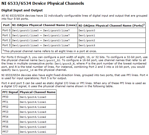
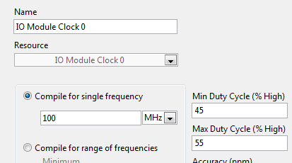
Following this discussion on inputs glitching, I learned that I need to use the area of the sampling clock to read nodes to HAVE it in my 5734 OR. So I right click 'FPGA Target'-> "New FPGA Base Clock" and selected "IO Module clock 0". In general, I followed the instructions at http://www.ni.com/pdf/manuals/375653a.pdf
Issues related to the:
- I noticed that, regardless of the value I put in "Compile single frequency", timed loops using this clock works at 120 MHz. Should it?
- I want to gain at 10 MHz, no 120 MHz. is there a way to create a clock derived from the sample clock? (Right click on the clock gives me not the option "New FPGA derived Clock")
- In the example of the FIDL, engine of CQI on 5734 SMU - 7962R.lvproj, 'IO Module 0 clock' is configured to be compiled to "100 MHz" instead of 120 MHz. is there a meaning behind this value? (# 1, I understand that the value is ignored)
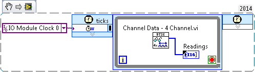
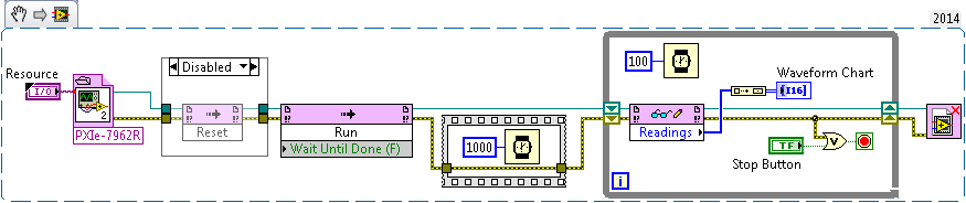
- The code example below, I get "error-61046 occurred to read/write control" unless I have excluded the "Reset" of the VI host node. This problem does not occur if I use on-board 40 MHz clock instead of the clock of Module e/s 0, (although I'd get glitched data). Am I wrong configured something?
- In my current, more complex program, I get the same error even with disabled node, if I stop and restart the host VI - but the next attempt would succeed.
- I have attached the sample file project, the screw and bitfile, where they are useful.
Hi FKSH,
You are right that you must Access your e/s on the 5734 NOR in the area of sample clock:
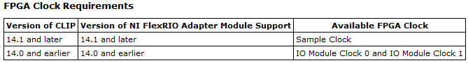
(this information is by using LabVIEW for the CLIP of 5734 OR)
It is a clock Module e/s 0 or sample clock based on your version of the FlexRIO driver you have installed. Based on your statements, looks that you use LabVIEW 2014, so be sure to have FlexRIO 14.0 or FlexRIO installed 14.1. If you have FlexRIO 14.0 or earlier, the sample clock will be IO Module clock 0. If you have FlexRIO 14.1 or later, it will be the sample clock:
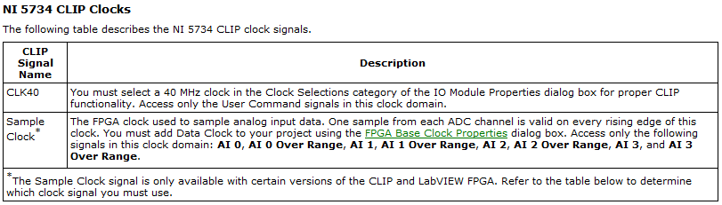
(also of the documentation NOR 5734 CLIP in help)
The only support for sampling rate is 120 MHz, unless you use an external clock CLK in and it must be between 50 and 120 MHz (see page 9 of the Manual). If you wish to purchase to 10 MHz, the best thing to do would be to sample the e/s to 120 MHz and then decimate the data by a factor of 12 (keep all 12 data points only and throw out the rest).
Regarding the FIDL, I'm guessing that you're referring to the configuration in the properties of the clock:
This configuration is not actually change the frequency of the clock. The compiler uses this value so that the logic can operate at the specified frequency, but the real clock is provided elsewhere (in this case, the FAM).
Finally, I saw error-61046 occurs more often because of the configuration of the internal clock. Make sure you use the clock on the right as the only cycle timed loop source as I mentioned above. In general, I do not recommend write directly on a 120 MHz indicator, as there are a lot of other logic that needs to be done in order to update the indicator. The data are sent to a domain different clock under the hood, so you can actually update the data and I suspect that there are some conflicts with the clocks. You also lose data as the host won't be able to read all the data before it gets crushed. Instead, I would use DMA FIFOs if you need all the data you acquire or to send the data to a different loop which will be responsible for the update of the indicator in a slower clock domain.
In general, I recommend always that the start-up of the examples in the Finder as a good place to check if the equipment works properly and as a reference for the correct configuration. Once you compile the code, you should be able to run it natively to acquire some data. "" "These examples will be under input and output hardware" FlexRIO "Modules e/s ' NI 573 X ' NI 5734.
Best regards
-
DAQmx task Read DAQmx with sampling frequency of 10 Hz produced much too much data
I have a simple configuration with a strain of channel 4 OR-9237 amp holds a carrier of series C of WLS - 9163 (wired ethernet mode) - Details probably does not matter.
I used MAX to create a DAQmx task associated with which all four gauges samples. The calendar setting is "Scan Loads" is continuous sampling, 2 k buffer (read samples) and 10 Hz rate. I guess that this task would generate 40 data values per second - 10 for each channel.
I have a simple loop of reading using DAQmx Read.vi that works always (without any stimulation time). Playback is set to read all available data and then pump it into a table.
In the attached example, I also added a few words of debugging to stop the loop after N iterations.As the loop is programmed with a 0.2 second period, I expect each pass of the loop to read about 8 samples or 2 samples per sensor. Instead, I get hundreds each passage. It's like reading has substituted the sampling frequency specified in the task of the unit. I absolutely need data to be material to the rhythm.
Where have I lost?
Thanks Adnan,
I changed your example I selected 'Strain gage' entry analog and then lowered the minimum and maximum thresholds to +-1-2. What happens is that each other in the loop, I 2048 samples or zero samples. The display flashes a whole line and then it clears any other past.
In response to your second post, I understand that the loop cannot run quite right that I select. I think that, but at a sampling frequency of 10 Hz, I have to sleep on the software side for nearly a minute before I built 2 K samples.
I played with the frequency of sampling, assigning to various values from 0.1 to 10000Hz. The behavior is the same until I approach the high rates where available samples remains to 2048-4096 sometimes, the display becomes continuous.
Ahhh, Darn. Yet another search was this link that points to the root of my confusion. The 9237 can taste arbitrary rates using its internal clock. Duoh! I wish that the pilots are smart enough to warn you if there is a discrepancy between the selected sampling rate and capabilities of the device
-
Interview with conditional count columns
Hello again,
I need your help again.
Sample data:
And my request:DROP TABLE TABLE_1; CREATE TABLE TABLE_1 ( "DEPT" VARCHAR2 (1) , "PD" VARCHAR2 (2) , "INMPD" VARCHAR2 (5) , "AGE" NUMBER ); INSERT INTO TABLE_1 (DEPT, PD, INMPD, AGE) VALUES ('A', '12', 'FALSE', TO_NUMBER('31') ); INSERT INTO TABLE_1 (DEPT, PD, INMPD, AGE) VALUES ('A', '12', 'TRUE', TO_NUMBER('15') ); INSERT INTO TABLE_1 (DEPT, PD, INMPD, AGE) VALUES ('A', '12', 'TRUE', TO_NUMBER('8') ); INSERT INTO TABLE_1 (DEPT, PD, INMPD, AGE) VALUES ('S', '12', 'FALSE', TO_NUMBER('31') ); INSERT INTO TABLE_1 (DEPT, PD, INMPD, AGE) VALUES ('S', '12', 'TRUE', TO_NUMBER('15') ); INSERT INTO TABLE_1 (DEPT, PD, INMPD, AGE) VALUES ('S', '12', 'TRUE', TO_NUMBER('8') ); INSERT INTO TABLE_1 (DEPT, PD, INMPD, AGE) VALUES ('A', '05', 'FALSE', TO_NUMBER('31') ); INSERT INTO TABLE_1 (DEPT, PD, INMPD, AGE) VALUES ('A', '05', 'FALSE', TO_NUMBER('15') ); INSERT INTO TABLE_1 (DEPT, PD, INMPD, AGE) VALUES ('A', '05', 'TRUE', TO_NUMBER('8') ); INSERT INTO TABLE_1 (DEPT, PD, INMPD, AGE) VALUES ('S', '05', 'FALSE', TO_NUMBER('31') ); INSERT INTO TABLE_1 (DEPT, PD, INMPD, AGE) VALUES ('S', '05', 'FALSE', TO_NUMBER('15') ); INSERT INTO TABLE_1 (DEPT, PD, INMPD, AGE) VALUES ('S', '05', 'TRUE', TO_NUMBER('8') ); INSERT INTO TABLE_1 (DEPT, PD, INMPD, AGE) VALUES ('A', '02', 'FALSE', TO_NUMBER('31') ); INSERT INTO TABLE_1 (DEPT, PD, INMPD, AGE) VALUES ('A', '02', 'TRUE', TO_NUMBER('2') ); INSERT INTO TABLE_1 (DEPT, PD, INMPD, AGE) VALUES ('A', '02', 'TRUE', TO_NUMBER('3') ); INSERT INTO TABLE_1 (DEPT, PD, INMPD, AGE) VALUES ('S', '02', 'FALSE', TO_NUMBER('31') ); INSERT INTO TABLE_1 (DEPT, PD, INMPD, AGE) VALUES ('S', '02', 'TRUE', TO_NUMBER('2') ); INSERT INTO TABLE_1 (DEPT, PD, INMPD, AGE) VALUES ('S', '02', 'TRUE', TO_NUMBER('3') );
This query gives me a new line for each priority axis.SELECT T1.DEPT , CASE WHEN TO_NUMBER(T1.PD) BETWEEN TO_NUMBER('01') AND TO_NUMBER('04') AND T1.INMPD = 'TRUE' THEN COUNT(*) END AS "PD02" , CASE WHEN TO_NUMBER(T1.PD) BETWEEN TO_NUMBER('05') AND TO_NUMBER('08') AND T1.INMPD = 'TRUE' THEN COUNT(*) END AS "PD05" , CASE WHEN TO_NUMBER(T1.PD) BETWEEN TO_NUMBER('09') AND TO_NUMBER('15') AND T1.INMPD = 'TRUE' THEN COUNT(*) END AS "PD12" , COUNT(*) AS "TOTAL" FROM TABLE_1 T1 GROUP BY T1.DEPT , T1.INMPD , T1.PD ORDER BY T1.DEPT
But I want a line for a Department like this:
PD02 online should be counted if the Democratic Party is between 01 and 04 and INMPD is set to TRUE.DEPT PD02 PD05 PD12 TOTAL ---- --------------------------------------------------- --------------------------------------------------- --------------------------------------------------- --------------------------------------------------- A 2 1 2 9 S 2 1 2 9
PD05 online should be counted if the Democratic Party is between 05 and 08 and INMPD is set to TRUE.
PD12 online should be counted if the Democratic Party is from 09 to 15 and INMPD is set to TRUE.
TOTAL online should be the total of the values for the Department.
Thanks to you all.
ReiniHello
Freakster235 wrote:
Hi Frank,.That's right, the word "the" should be used 3 different words "der, die, das" in German.
You must use at least 3 different words. Don't "dem", "den" and "' also means 'the '?
In fact, you write very well English. In fact, you should write more of it: you should post an explanation of what you're trying to do. Can help people like me you write queries that get good results for small sets of sample data, but unless we understand why you want that the results, we could give you solutions that just happened to work for the small sample sets, more or less by chance.... But thar isn't the truth ;) I have a total of 8 so not 4.
If you want to count separate orders; and create_date has nothing to do with this problem. Is this fair?
If so, do not use create_date in the GROUP BY clause from got_aggregates;. Use order_nr instead:WITH priorities AS ( SELECT '01' AS min_priority, '03' AS max_priority, 5 AS max_age FROM dual UNION ALL SELECT '04', '08', 8 FROM dual UNION ALL SELECT '09', '15', 30 FROM dual ) , got_aggregates AS ( SELECT t1.dept , t1.priority -- , t1.create_date -- ***** NOT NEEDED ***** , MAX (CASE WHEN t2.wo_step = 'A' THEN t2.step_date END) AS first_a_date , MAX (CASE WHEN t2.wo_step = 'U' THEN t2.step_date END) AS last_u_date FROM table_1 t1 LEFT OUTER JOIN table_2 t2 ON t2.order_nr = t1.order_nr -- ***** CHANGED ***** GROUP BY t1.dept , t1.priority , t1.order_nr -- ***** CHANGED ***** ) SELECT a.dept , COUNT (CASE WHEN p.min_priority = '01' THEN 1 END) AS pd02 , COUNT (CASE WHEN p.min_priority = '04' THEN 1 END) AS pd05 , COUNT (CASE WHEN p.min_priority = '09' THEN 1 END) AS pd12 , COUNT (*) AS total FROM got_aggregates a LEFT OUTER JOIN priorities p ON a.priority BETWEEN p.min_priority AND p.max_priority AND NVL ( a.last_u_date , SYSDATE ) - a.first_a_date <= p.max_age GROUP BY a.dept ORDER BY a.dept ;There is no need to include either create_date or order_nr in the SELECT got_aggregates clause.
In your new sample data, there is an order_nr that exists in table_1 but not in table_2. In order to count this order_nr, we use an outer join in got_aggregates.The results should look like this:
DEPT  PD02  PD05  PD12  TOTAL
----  ----  ----  ----  -----
A        0     0     2      6
S        0     0     0      2
That's what I have now:
D PD02 PD05 PD12 TOTAL - ---------- ---------- ---------- ---------- A 0 0 2 6 S 0 0 0 2 -
Hey Dan!
I tried to get your universal clock from counting to stop when it gets to 00:00:00, but this part threw me:
If (clockTime < 0) {}
sign = "-";
clockTime = - clockTime;
} else {}
sign = "";
}
I tried
If (clockTime < 0) {}
clockTime = 0;
but he ignored. How do you want to do to stop the meter (upwards or downwards)?
I would change the line just before the section that you modified.
Countdown, stop to zero:
Replace this:
clockTime = clockStart + rate*(time - inPoint);with this:
clockTime = Math.max (clockStart + rate * (duration - inPoint), 0);
Stop, count to 100, use this:
clockTime = Math.min (clockStart + rate * (duration - inPoint), 100);
Dan
-
Keep the impulses generated in synchronization with an external clock
I use a card PCI-6602 with Windows 7 and the ANSI C library.
I need a continuous 100 HZ output to stay in sync with an external 1 HZ clock.
I started with the example in the http://www.ni.com/example/27415/en/
If I send impulses 99 I can retrigger every second without problem
If I send 100 pulses on the next retrigger is missed and impulses come out of all the other seconds.
I have here a way around this?
TaskHandle taskHandle = 0;
char * chan = ' Dev1/ctr0. "
float64 duty = 0.5;
float64 freq = 100;
uInt32 slow = DAQmx_Val_Low;
float64 initDelay = 0.0;
uInt32 edge = DAQmx_Val_Rising;
char * triggerSource = ' / PFI19/Dev1;
uInt32 numSamples = 100;DAQmxCreateTask("",&taskHandle);
DAQmxCreateCOPulseChanFreq(taskHandle,chan,"",DAQmx_Val_Hz,idle,initDelay,freq,duty);
DAQmxCfgDigEdgeStartTrig (taskHandle, triggerSource, edge);
DAQmxCfgImplicitTiming (taskHandle, DAQmx_Val_FiniteSamps, numSamples);
DAQmxSetStartTrigRetriggerable (taskHandle, 1);
DAQmxStartTask (taskHandle);To some of the devil, because your timing is a so much is little too limited:
-How is crucial to generate exactly 100 Hz? What happens if you have generated to, say, 100,01 Hz? This cheat of tiny bit timing could give the Council sufficient time to rearm and retrigger every 1 second.
-How certain are you that the external signal is a rock solid 1,000000 Hz? If it can vary quite a bit from your Council, you will not be able to know in advance what time window, you need to meet your 100 pulses in
-assuming that the external signal is a perfect 1,000000 Hz and that you need to generate to (what your Board of Directors believes) a perfect 100,0000 Hz, can you live with generation of 99 impulses instead of 100?
-How do you intend to treat lightly divergence that is almost certain to exist between the idea of external signal of 1.00000 dry and the idea of your Board of Directors of 1.00000 oscillator dry? I remember well, the 6602 is valued at something like 50 parts per million accuracy of calendar, give or take a little variability of temperature based
Otherwise, no specific magic answers. If really stuck, I have an idea, or to do something with several counters are working together, but have not thought enough details have confidence in the feasibility.
-Kevin P
-
Does anyone know how to add a folder with sample data the installer to labview
I have set up a program to install the application to a project I'm working on that. I want to add a folder to the installation with some sample data files. Currently, I added a readme file that tells the user to decompress a file included with the Setup program in a certain folder. Is there a way to automate the process and include this with the installer?
First add all the files you want to include in the project. Then in the properties of the installer:
1 use tab destinations to add a folder if you have the sample files contained in their own folder.
2. on the file source page, expand "My Computer" and find the files in the project you want to add.
3. Select the folder you want to that they be located on the right side and click the right arrow.
-
Xincrement is not agree with sampling frequency
I use two PXI-5114 scanners that are being synchronized. I am taking 5 seconds worth of data. I have = 1e3 sample rate and record length = 5e3. I get only about 1.3 seconds worth of data. I looked at the actual length of the record and the actual sampling frequency outputs and they said the same thing as the façade made. I looked at and then the info out of the Cluster.vi of Fetch NiScope Multi Wfm and he had the same record length, but the value of Xincrement is 262e-6. This fits with what I get. Any ideas?
Thanks in advance.
Hi AT1,.
Thanks for posting. What you see, this due to the fact that the minimum sampling rate of the PXI-5114 is 3.81 kech. / s. The digitizer will force any value less than 3.81 kech. / s up to this value, so a record of 5000 samples take 1.31 seconds to acquire. If you are looking to acquire 5 seconds worth of data, I recommend to increase the length of record about 19 050 samples, which should be about 5 seconds worth of data. Let me know if this would work for your application.
Kind regards
Joe S.
-
PEAK counting with burst count, etc.
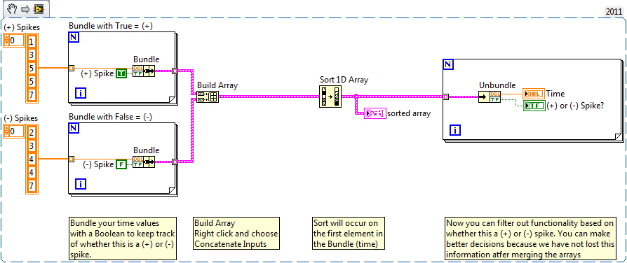
I am writing a program which has peaks (+ spikes) and valleys (-spikes) and gusts (defined as 3 or more pics in a row with 1 msec or less between them) and peaks and valleys which lie in 1 ms of each other. Pic count part is easy, but I myself doubt on the other parties. Can someone take a look and let me know if I'm away from base? Right now I have all the data to test, but the signals that we are GET-like (actually looking at neuronal cells and signals recorded from Microarrays). Thank you
mtgjbird01,
The main question you are running in meets the sign (+) and (-) tables of pic. When you do so, you can say more if the item is a (+) or (-) PIC.We need somehow to keep this information and then still be able to sort. This is possible by the grouping of the value Double with a Boolean, and then apply the sort. After sorting, we will always know whether it is a (+) or (-) points based on the Boolean value.
Maybe you are looking for
-
If I sell or give my Mini iPad (1st generation) with WiFi cellular (Verizon) can I keep my SIM card? OR once I deleted everything out of the device, the SIM card will be ready for a new user and all my information have also been deleted?
-
Help me please my ipad model A1395 FCC ID:BCGA1395 Rated 5.1V = 2. 1A max, EMC 2560 meets the Canadian ICES-003 Class B specifications, FCC ID:BCGA1395 and IC:579 C-A1395 DM series * km/h < personal information deleted by host >
-
HP Pavilion g series: voice of the unwanted ads
For the first time I'm ads of hearing that seem unrelated to the site I'm. There is no visible advertising, just noise. I had to cut the sound, because they were so boring. How can I get rid of them?
-
I recently downloaded rockbox and my sound does not work so I uninstalled everything, but my sound still does not work. I have a sansa e250. I returned and deleted alll these settings my mp3 rockbox. So still I donot have sound. I tried reseting my s
-
HP 90w Smart AC Adapter laptop
I lost the warranty information and broke my dongle. Who can I call about this?