arithmetic on an analog input channel
I use a NI 9239 card to read four analog inputs. The sample data are interleaved. On my fourth channel, I want to split each sample by 2 and subsequnectly plot these data to a chart of the band. I sought the help of NOR-DAQmx ways across this channel, but I have not had much luck doing so. I am relatively new to LabWindows and am not positive if there is a built-in function to perform this kind of task, or if I should think to create my own function to split each fourth sample by 2.
Thank you.
You don't need to change the data table. The graph can do for you.
Look for the setting of 'gain' on the y-axis related.
(double-click the chart control and change the y-axis settings)
Hope this helps,
Tags: NI Software
Similar Questions
-
6225 PCI residual voltage in the analog input channel
Hello, I'm new to the Forum and just start working hands with NI hardware/software/etc.
I use MAX (differential setting) to monitor an input channel analog (ai71) through a PCI-6225 card with an SCB-68. The voltage displayed in this MAX sometimes regular 10.6 volts and sometimes intermittent noise 0 to 10.6 volts or vague angular. I watched the disintegration of noise and waves to zero. The voltage displayed in MAX is (seemingly at random) changes when a voltmeter is used to measure the voltage between pins 1 and 35 (with no wire signal)
When an external square wave (2.7 volts DC) is applied to the pins 1 and 35 in the SCB - 68 the value in MAX is dominated by the 0 - 10.6V 'noise', while a voltmeter between pins 1 and 35 simultaneously shows the square wave.
Any suggestions? Thank you in advance.
If you dig into the data acquisition specifications, input voltages must be referenced to the mass of AI or you may damage the Board. Have a good read of this article: wiring field and considerations of noise for analog signals. Since you're probably dealing with a differential signal with no mass, what you want to do is to add resistance on each side of the signal to ground. This article recommends until 100kOhm 10kOhm resistors.
-
improve the precision of the analog input channel
Hello
I use a PXI-6259 to read several analog voltages and I can't seem to get the same precision when playing of multiple channels over a single channel using the MAX test Panel. How can I add delays to the digitization of the MUX to improve accuracy? Or are other ways to improve accuracy?
Thank you!
In addition to what the other posters minimizing the frequency clock source impedance and conversion, there are a couple of other things you can do to minimize the error:
1. If you can not reduce the clock rate conversion due to a high sampling rate, you could try adding "dummy" additional channels, where you have large jumps in the measured voltage. For example, if you need to measure three channels to about 5 V and three channels to about 2.5 V, you can read the string of first 5 V and the first 2.5 V additional time (and throw away the measure). This has the same effect by reducing the clock frequency conversion, but only for the channels of problem.
2. reorganize your channels by the expected voltage level. Using the above example, all the 5 V channels, then all channels V 2.5 read. Don't alternate between 5 V and 2.5 V channels.
3. Add the ability to the input terminals. The capacitor is still in all of your input signal, it provides a reservoir for fast charge/discharge of the ADC input capacitance. If your input signal changes fast, well, make sure that the additional capacity will not filter the signal that you are interested in.
Mark Moss
Electrical Validation engineer
GHSP
-
How to read and scale of multiple analog input channels
Hello
I'm reading the data of several types of sensors, with readings of 4-20mA. What I'm trying to do, is have a pressure transducer, a flow meter and a RTD sensor all connected on channels 1, 2 and 3 of my cDAQ using DAQmx. After channels are put on the scale, I need to see all the data in a chart of the wave with the scales on each side, identification of pressure, temperature and flow. Finally, I need to write that data to a text file. TDMS is fine, but for now, I'm working with a CSV file.
So far, I got my VI to read the data channel and the data on the scale correctly. I'm also writing to the file works properly. However, when I try to change the second channel, nothing happens or I get an error. Can someone help me on this? I have experience to come Monday to it so Im a little short of time. Ive fixed this Ive got so far (Ive got several versions of this VI trying to do this in various ways).
With respect to the accuracy of the readings for channel 0, Ive been using a deadweight Tester and a manometer calibrated to see readings. So far, these are correct, and I was able to calibrate other gauges with this interface.
Way easier and more foolproof that I found to do this is to set up several channels using an Express VI (DAQ assistant) and then made a right click on the object of block diagram and 'open the fron Panel '. Click OK to the warning and you will be pressented with an example of a multi-channel configuration.
As to the best way to get 90% it when learning DAQ configuration...
-
How to use 1-channel analog input for start/stop aquire sample second channel input analog?
I have a little problem. I've just been programming in labview for 2 weeks.
I'm trying to figure out how to use my channel of analog input on the USB-6009 case for start/stop (reference trigger and start) presented to the second analog input channel samples.
I need the first analog input string to operate continuously and control sampling on the second. When the second channel will start sampling program brings a new graph each time and saves it (I have all this that figure out).
How can I configure the trigger so the lance program presented in for the second channel when the 1 channel reached above 2V (e.g.) and stop when it falls below 2V.
I use a pressure force sensor on the first channel that gives me straight (up to) 5 V when it is pressed and nothing when it is not...

Thank you.
Grand... Thanks for the information!
But can't I then make a 1 channel instead and wait until that meat of the max element value?
-
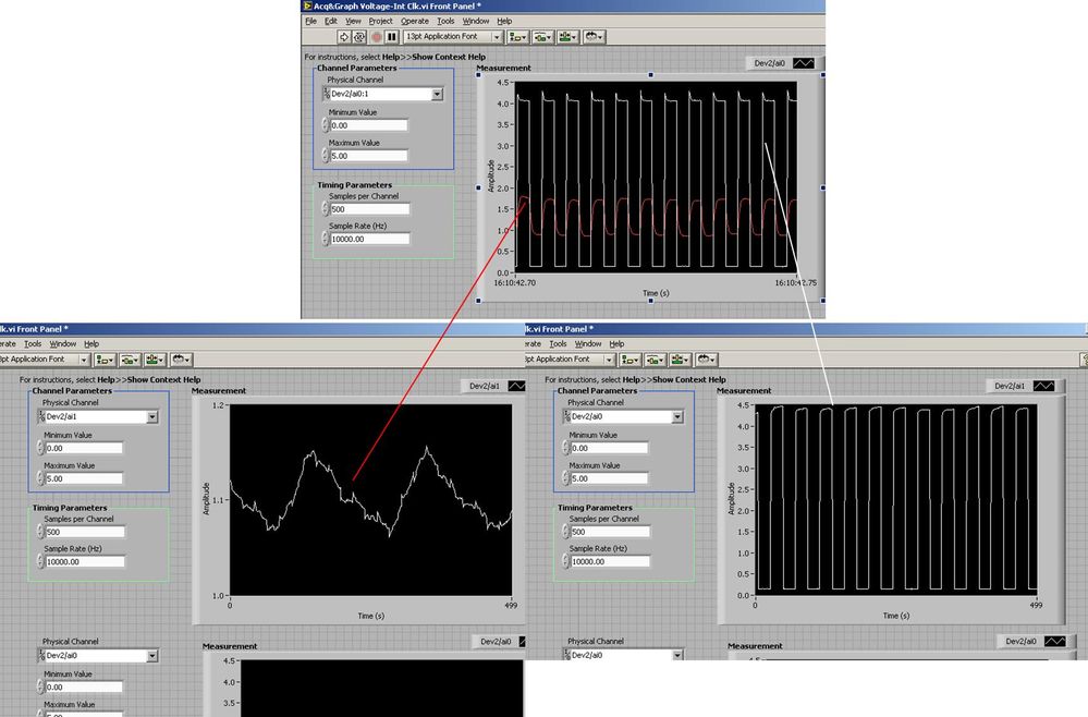
Several analog inputs seem to change any of the other (details DAQ: 2120 BNC and 6062E)
I use the BNC 2120 DAQ board connected to the data acquisition card 6062E to record two analog inputs. An entry is connected to ai0 and the other at ai1. Example vi: "Acq & graph int clk tension" has been used to measure the two entries with the value read NChan NSamp vi (channels being dev2 / ai0:1). The output is the top graph in the image. However, this seemed a bit strange to me that one of them should be modulating with a different frequency. When I record both entered individually (two in low pictures) they are indeed different since the entries shown in the top graph.

Why this would be the case, and how can I overcome this to measure the real signals?
Thank you!
The E series card takes the samples as soon as possible. Thus, for example,.
If you have 16 analog input channels but you only read of
channel 0 and 1, the map will show the channels 0 and 1 right
After and then wait 14 'ticks '. What's that little run-in
the origin of the afterglow.
I think you can get the card to wait a certain
number of ticks with a property node. I have attached a screenshot. You
can find the property node in the palette of functions >
Measurement of e/s > NOR-DAQmx > node Timing. Expand it
Property node so there's two entrances. The properties are in
Left click on the node and going more > converted >
Its properties delay units and sampling clock delay and delay that
you want.If the phase is important so the above is not the best
the option because it causes a delay in phase. So, if you need true simultaneous
sampling, then you will need different hardware. The S series is everything
simultaneous sampling.Or, rather than the Delay property and delay units, try the Rate property
find more > converted > rate.If this is not
work either, you can move the second signal source to, say, AI8 and
Connect everyone to the ground. Readings for these, but just do not take into account
the data. In this way the ADC will sag to the ground at the time where that can happen
the second string in the way so that you should not see this frequency
ghosting on the other channel. -
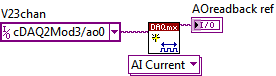
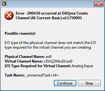
Read analog output channel value internally
According to this you can read the values of analog output of return without having to physically connect the wires.
By using the technique described in the example given (DAQmx_Read_Output_Internal_Channels.vi) I'm reading a current area of OCCUPANCY on my compactDAQ cDAQ-9174 with a module of analog output current OR-9265.
The output channel is created in MAX and my vi can write values to him without problems
But when I try to create an analog input channel to read the output, an error occurs.
What I am doing wrong?
This is not supported by my hardware?
Or is the example given in the above incorrect link?
The example is 10 years old. Maybe, it does not work in LV2013.
Hi Jocker,
The link was not attached to your message, but I guess that's it: http://digital.ni.com/public.nsf/allkb/CB86B3B174763C3E86256FFD007A2511 as there the example of vi you mention.
The error you are getting is due to the use of the channel for analog output and trying to configure the task as a task of entry. You must use _aoX_vs_aognd as the channel of the task rather than on the output channel. This compares to the ground for the analog output values.
The NI 9265 is not on the list of the C Series modules that have internal channels:
So I guess that the module is not able to compare its output to ground. He would appear in the dropdown of the channel names if available.
Pete
Applications Engineer OR
-
Multifunction analog input/output
I use USB X series 6356 to my experience. I send out a pulse of tone by analog output channel to an actuator.
And receive the signal of response of a sensor to an analog input channel. I've included a screenshot of VI.
The question is, I get the output of the signal response signal as well.
If I send (via the output channel), a burst of your 10 KHz which begins at t = 0.
I see that the tone burst into my plot of input channel as well (at t = 0).
Please, let me know if I use the good VI (I build it according to multi-multifunction-synch I AO VI of examples).
I use the loop to remove 60 Hz noise (by an average of more than 100 times) signal.
Hi Vishnu7,
From what you describe, it seems that you can meet with some ghosting or crosstalk on your analog input channel. Take a look at this knowledge base article and see if it matches with what you see.
http://digital.NI.com/public.nsf/allkb/73CB0FB296814E2286256FFD00028DDF
-
LabVIEW think my NI USB-6008 has only analog inputs
I am using an NI USB-6008 box to run a route of analog input and analog output.
If I do a constant material DAQmx channel and out the finger tool and pull down... and it offers me 8 analog inputs on Dev1 and nothing else. I've nothing else connected to this computer, but the box USB-6008. A USB-6008 doesn't even have 8 analog input channels.
I'm a bit confused.
-
6036E PCMCIA + DAQmx (analog input) seems to only read in blocks of 512 samples of data
Hello people,
I ask this question before I post any code or software versions etc to see if there is a simple answer.
I use a PCMCIA card 6036E to read an analog input channel (DAQmx... i. e create task, create the channel, set the altimeter (continuous samples), task, read in a programmed software loop while (ASAP)). No matter how I put my sample rate, number of samples per channel (i.e. size of buffer), or the number of samples to be read, it looks like I can get multiples of 512 samples.
Here are some samples freq (Fs), the 'number of samples to read' asked and the actual number of samples read:
FS numberOfSamplesRequested numberOfSamplesActuallyRead
200Hz 20 512
1000 1024 5000Hz
2000 2048 5000Hz
QUESTIONS RELATING TO THE:
1 is this 'normal' behavior a 6036E PCMCIA card?
2. in the case, has anyone who may have seen this problem determined the cause and how to "fix it"?
Best regards
Chris
chassan wrote:
Hello people,
QUESTIONS RELATING TO THE:
1 is this 'normal' behavior a 6036E PCMCIA card?
Sort of.
2. in the case, has anyone who may have seen this problem determined the cause and how to "fix it"?
Best regards
Chris
Systems PCI DMA is used to transfer
the data, daqmx and receive messages when the number of samples are
acquis. Now on PC-card that does not work and the data is transferred
When the edge buffer is full (after 2 k of data) to 2 channels
10 Hz, it can take some time.
There is a work-around, there is a property where you can set the transfer mechanism (I have not daqmx on this PC), or the daqmx polling mechanism. Try these.Found a document KB.
Tone
-
6008 analog input - invalid values
Hello
Does anyone know how the analog input voltage 6008 invalid handles? Specifically, what happens if the circumstantial channel is configured for a 0 - 10 range v and a voltage negaitve, (-19.0) volts is placed on the analog input?
I use the library, C/C++, OR-DAQMx library. The call that I use to set up the port of AtoD is:
DAQmxErrChk (DAQmxCreateAIVoltageChan (taskHandle, AINPSTR, "", DAQmx_Val_Diff, 0,0, (float64) s_dMaxAnalogInputVoltage, DAQmx_Val_Volts, ""));
where: s_dMaxAnalogInputVoltage = 10.0;
and
DAQmxReadAnalogF64 (taskHandle, 1, 1.0, DAQmx_Val_GroupByChannel, values, 5, & not read, NULL);
to read the circumstantial.
What will happen if any illegal input voltage is applied. I know that everything is a wide range, so I don't talk about something like -60 to + 60 volts.
Thank you
-Neil shore
These specifications are in the datasheet of the product - link to it in the product specifications of the page tab.
And no, there is no error generated when the input is out of reach. Scaling the proper entry so that this doesn't happen. or if this is the case, your software recognizes that is higher than expected.
-
read the multiple analog inputs at the same time
Hi all
I use USB-6001 and want to develop an application to multiple tasks in C++. I try to read several analog inputs at the same time, but got some errors. To put it simply, I copy one of the sample code to read in analog data in a channel, and then turn it into function. Then I call this function to thread with the names of different poles (for example Dev1/ai0, Dev1/ai1) and I come across this error:
"The specified source is reserved. The operation can not be specified such complete"code of State-50103
I have search the forums, this may be because I use the hardware timing in this function, and this material timing cannot be used simultaneously by multiple tasks. I may have to put all the lines, I want to read in a single task (such as Dev1 / ai0:1). This way I can read two lines at the same time. However, when I try this, I encounter another error:
Status code "buffer is too small to contain the data read" - 200299
So here is my question, what should I do if I don't want to read the multiple analog inputs at the same time? Is the thing that hard time cannot be used by several true task? If I have to read several lines to a single task, how to set the settings?
-
How to compare analog input signals?
Hi all
I use PCIe6363 DAQ to collect the analog input signals. Mode of input signal is continuous and single channel several example. The sampling frequency is 2 ms/s, number of sample 100KS or less. This means DAQ 100KS of collect and draw a line/curve. I want to compare the two curves. The problem is DAQ continuously collects data and plot also continuously. Would you please is it possible to compare the curves of this operation continuous operation. The main goal is to justify whether or not the signal of incomeing maintain consistency.
Thank you very much
Azim
You can store a waveform in a shift register. Then you have in memory compared to the new waveform.
-
How to merge and write analog inputs, and export data to a tdms file?
I have a vi who writes analog inputs in tdms files. I also want to write the analog output signals, which are 2d table entries in the same PDM file with additional columns representing the analog output signals. How can I get this feature?
Ashaironix wrote:
Hey Crossrulz,
So you're saying that writing two files tdms with entries as HAVE and AO, will write everything in a file single tdms AOs and Ais?
N ° you write in the same file, just different GROUPS. TDMS is a hierarchical data format. You have the file, group, channel. Waveform data will actually in the channel data. But you can have metadata on any level. So, I do a group I and a group of the AO.
-
Frequency measurement of analog input using DAQmx C APIs on SMU-6341 map
Hello
I use Linux DAQmx and attempt to measure the frequency of analog input using the map DAQ SMU-6341.
There is an ANSI-C frequency measurement example:
/ usr/local/natinst/nidaqmx/examples/ansi_c/Analog_In/Measure_Frequency/Cont_Freq-Int_Clk-SCXI1126
However, the call to DAQmxCreateAIFreqVoltageChan results in the following error:
DAQmx error: selected physical channel does not support the type of measure required by the virtual channel you create.
Create a channel to a type of measure that is supported by the physical channel, or select a physical channel that supports the type of measure.
Property: DAQmx_AI_MeasType
Required value: DAQmx_Val_Freq_Voltage
Possible values: DAQmx_Val_Current, DAQmx_Val_Resistance, DAQmx_Val_Strain_Gage, DAQmx_Val_Temp_BuiltInSensor, DAQmx_Val_Temp_RTD, DAQmx_Val_Temp_Thrmstr, DAQmx_Val_Temp_TC, DAQmx_Val_Voltage, DAQmx_Val_Voltage_CustomWithExcitationTask name: _unnamedTask<0>
State code:-200431
DAQmx does support the function of the frequency on the map 6341, or should we use examples of voltage and calculate the frequency manually?
Frequency of HAVE it is a type of channel that has been supported only on the SCXI module name of the example.
You will need to use a voltage input channel and calculate the frequency manually for your device.
Maybe you are looking for
-
Ultiboard - unable to get a connector SCSI 68
New to Ultiboard, so I could use some help! We were able to create a fingerprint for line 4, staggered 68 pins SCSI Connector (Honda PCS-E68LMD). The netlist identifies all serving pine when the part is imported from Ultiboard 10.1, but Ultiboard wil
-
HP 5400 printer light blinks, but does not print
HP 5400 printer light blinks, but does not print
-
I can't delete or open mail received on 08/05/11. All mail is fine after.
It's six normal emails without obvious problems.
-
Hello I want to load a Web page in a Web view control. I create the WebView, set the url, and finally add the WebView to the container, but nothing appears. Am I missing something? Thank you
-
I use flash.text.TextField to enter & showing a large amount of text. It handles well the scroll jumps & line. How can I change the font type & size? try to get the ti to match the default value of qnx.ui.text.TextInput. Thank you