6008 analog input - invalid values
Hello
Does anyone know how the analog input voltage 6008 invalid handles? Specifically, what happens if the circumstantial channel is configured for a 0 - 10 range v and a voltage negaitve, (-19.0) volts is placed on the analog input?
I use the library, C/C++, OR-DAQMx library. The call that I use to set up the port of AtoD is:
DAQmxErrChk (DAQmxCreateAIVoltageChan (taskHandle, AINPSTR, "", DAQmx_Val_Diff, 0,0, (float64) s_dMaxAnalogInputVoltage, DAQmx_Val_Volts, ""));
where: s_dMaxAnalogInputVoltage = 10.0;
and
DAQmxReadAnalogF64 (taskHandle, 1, 1.0, DAQmx_Val_GroupByChannel, values, 5, & not read, NULL);
to read the circumstantial.
What will happen if any illegal input voltage is applied. I know that everything is a wide range, so I don't talk about something like -60 to + 60 volts.
Thank you
-Neil shore
These specifications are in the datasheet of the product - link to it in the product specifications of the page tab.
And no, there is no error generated when the input is out of reach. Scaling the proper entry so that this doesn't happen. or if this is the case, your software recognizes that is higher than expected.
Tags: NI Hardware
Similar Questions
-
Cut-off for the 6008 analog input voltage
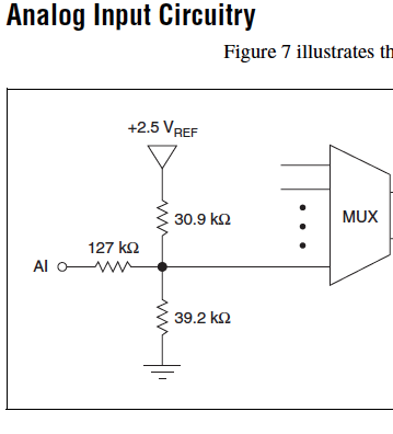
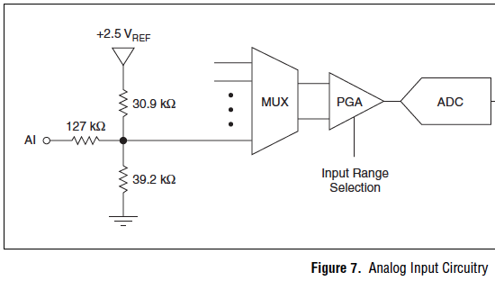
I am using the analog inputs NI USB-6008. The specification says they have a 144 k ohms input impedance. But it does not say what is the cut-off voltage. If you leave a disconnected and measure the voltage you will get 1.4 volts. So I guess it's the cut-off voltage, but it is not spec'd.
Someone agree that these Amnesty International isn't terminatied by 144 k - ohms to 1.4V? Is this in the documentation somewhere?
Figure 7 on page 16 of the NI USB-6008/6009 User Guide and specifications shows the strange input of this unit circuit.
Lynn
-
Hello
The data entry in LabVIEW by my USB-1208LS is accurate, but the analog input voltage values are quantified (there are only a few repeating values: 0,691 0.696 0,701 0.696 0,701 0,691 0,691 0,691, etc..). I am able the tensions of four photocells, propelled by the + 5V of USB-1208LS. Each cell is measured in a different channel using the differential input mode. Is it possible to fix the quantification of data?
I don't know if it's a problem of LabVIEW, but attached is my diagram, in the cases where I'm not seized the tension properly.
Thank you in advance.
On the input range, the resolution of this device is about 5 +/-10 V mV, which is exactly what you see. The resolution is established by calculating the length of the total voltage range (20 V) and dividing by the number of steps or bins the A/D converter on this beach (2 ^ 12 = 4096). Yes, resolution = 20/4096 = 4.883 mV.
To get the best resolution, you will need to use a smaller range (if your signal wil fits into a smaller range) or get a DAQ hardware with a higher resolution, for example a 16-bit converter, or 24-bit.
Lynn
-
Issues of analog input DAQ-6008, voltage not zero to pin when you are offline
I use the 6008 NOR-DAQ to produce a series of tensions and then read a sense resistor using the analog input (CSR). I noticed that my analog input gives me 1.3 V, when I probe it (compared to the mass of the device), when it is completely disconnected. This changes the reading to give me a different measure of sense than expected resistance.
Why is my pin for analog input non-zero? Any help would be appreciated. Thank you!
The 1.3 V is expected. The USB-6008-and-6009 case have the strangest input of the world circuit. The input impedance is approximately 144000 ohms terminated in 1.4 V. check the document User Guide and specifications.
Lynn
-
LabVIEW think my NI USB-6008 has only analog inputs
I am using an NI USB-6008 box to run a route of analog input and analog output.
If I do a constant material DAQmx channel and out the finger tool and pull down... and it offers me 8 analog inputs on Dev1 and nothing else. I've nothing else connected to this computer, but the box USB-6008. A USB-6008 doesn't even have 8 analog input channels.
I'm a bit confused.
-
reading of the analog inputs with RPC
Hello
Because LabVIEW can not handle this (in VI; the value that you have saved the excel file has not been the same, that I saw during the measurement...) This confused me for a long time
 ), I want to write a C++ program (IDE: Dev - C++) which can read & record 2 analog inputs of the NI USB-6009 box. For this, I looked for an example of National Instruments and I found a little. But my problem is that I can't even use any example, because it has always held a mistake, after that I have compiled and started.
The error once the task has been created and has the :-200220 error number with the description "device identifier is invalid. But I do think that its invalid, because it's the xP example
I must say that I am new in programming C++, which means I could have a rookie mistake. And I couldn't find documentation or something for the NOR-DAQmx library.
Someone has similar problems with DAQmx and C++ and know how to fix? I don't really know what I can do now without a working example or documentations...
Hi Mario
It's the same thing. You didn't just save all of the data:
Please take a look at my comments in the attached VI.
Christian
-
USB 6008 analog i/o has stopped working
Hello
I have been using a USB-6008 for a few weeks now and it has worked well. I've been using the outputs digital, analog inputs and outputs this morning and they worked very well. I worked on something else for an hour or two and then resumed using the 6008, find the analog pins have stopped working. The show output analog on 1mV any value I send to them and the analog inputs always read - 10.3, despite limits MAX being set to 0 and + 5 (and me only using 0 - 5V on them). I tried all the inputs and outputs, in all ways (CSR, diff) with the same results. The digital outputs all work very well. Yes, he is grounded properly. Yes, the wires have continuity. My multimeter don't lie about me, either.
I took the MAX test panel to solve the problems. The unit passes its tests of self-control, and my Labview program does not return errors by contacting the 6008. I don't connected the 6008 which could exceed the voltage or the current limits of entrances and exits. In fact, all I did was unplug it when I stopped using it as soon as possible and then reconnected it when I went back to work. The material to which it is connected has been turned off during this time.
Any ideas? Thank you.
Problem is solved. If anyone finds this is interested, the problem was at the level of the material, that the 6008 has been connected. I'm covering, among other things, to a PIC Microcontroller. I just changed the oscillator on the PEAK, and inadvertently changed parameters parameters of the ADC as well. This caused the pin used as my reference voltage (connected to + 2, 5V output of 6008) to transform itself into a digital camera of output, a value of 0. This short-circuit the + 2, 5V output of the 6008, causing it to close.
Lesson learned: check your material carefully, even if it does not make the difference in a first time!
-
Input signal is set to +/-0 .5V when it is connected to an analog input
Hello
I have a difficulty connect an analog source to the analog inputs of my acquisition of data (USB-6215). The analog signal is output operational amplifier through a 10 k resistor. I wore the signal out of the amplifiers is 10V peak, I then move the probe across the 10 k (the analog input terminal) and the signal is clipped to +/-0 .5V. If I reduce the amplitude of the signals of source less than 0, 5V Ridge there is no clipping.
Maybe the analog input range the value +/-0 .5V which is causing this as a form of protection? I don't have a LabView to try to change the input range as I do just the wiring.
Analog source is connected to him HAVE 0 and the ground of the analog source is connected to the GND AI.
Thanks in advance.
J
Joel-
Have you tried to read the data through the data acquisition device? If that's what you try to do, I'm curious about what we read.
If you have measurement and Automation Explorer, go ahead and open a Panel to test for the unit and see what are your tensions.
Let us know how it goes.
-
Several analog inputs seem to change any of the other (details DAQ: 2120 BNC and 6062E)
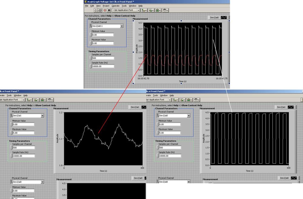
I use the BNC 2120 DAQ board connected to the data acquisition card 6062E to record two analog inputs. An entry is connected to ai0 and the other at ai1. Example vi: "Acq & graph int clk tension" has been used to measure the two entries with the value read NChan NSamp vi (channels being dev2 / ai0:1). The output is the top graph in the image. However, this seemed a bit strange to me that one of them should be modulating with a different frequency. When I record both entered individually (two in low pictures) they are indeed different since the entries shown in the top graph.

Why this would be the case, and how can I overcome this to measure the real signals?
Thank you!
The E series card takes the samples as soon as possible. Thus, for example,.
If you have 16 analog input channels but you only read of
channel 0 and 1, the map will show the channels 0 and 1 right
After and then wait 14 'ticks '. What's that little run-in
the origin of the afterglow.
I think you can get the card to wait a certain
number of ticks with a property node. I have attached a screenshot. You
can find the property node in the palette of functions >
Measurement of e/s > NOR-DAQmx > node Timing. Expand it
Property node so there's two entrances. The properties are in
Left click on the node and going more > converted >
Its properties delay units and sampling clock delay and delay that
you want.If the phase is important so the above is not the best
the option because it causes a delay in phase. So, if you need true simultaneous
sampling, then you will need different hardware. The S series is everything
simultaneous sampling.Or, rather than the Delay property and delay units, try the Rate property
find more > converted > rate.If this is not
work either, you can move the second signal source to, say, AI8 and
Connect everyone to the ground. Readings for these, but just do not take into account
the data. In this way the ADC will sag to the ground at the time where that can happen
the second string in the way so that you should not see this frequency
ghosting on the other channel. -
Frequency measurement of analog input using DAQmx C APIs on SMU-6341 map
Hello
I use Linux DAQmx and attempt to measure the frequency of analog input using the map DAQ SMU-6341.
There is an ANSI-C frequency measurement example:
/ usr/local/natinst/nidaqmx/examples/ansi_c/Analog_In/Measure_Frequency/Cont_Freq-Int_Clk-SCXI1126
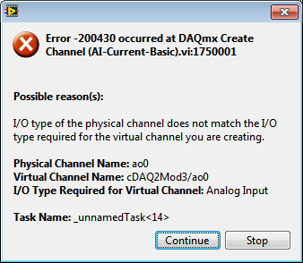
However, the call to DAQmxCreateAIFreqVoltageChan results in the following error:
DAQmx error: selected physical channel does not support the type of measure required by the virtual channel you create.
Create a channel to a type of measure that is supported by the physical channel, or select a physical channel that supports the type of measure.
Property: DAQmx_AI_MeasType
Required value: DAQmx_Val_Freq_Voltage
Possible values: DAQmx_Val_Current, DAQmx_Val_Resistance, DAQmx_Val_Strain_Gage, DAQmx_Val_Temp_BuiltInSensor, DAQmx_Val_Temp_RTD, DAQmx_Val_Temp_Thrmstr, DAQmx_Val_Temp_TC, DAQmx_Val_Voltage, DAQmx_Val_Voltage_CustomWithExcitationTask name: _unnamedTask<0>
State code:-200431
DAQmx does support the function of the frequency on the map 6341, or should we use examples of voltage and calculate the frequency manually?
Frequency of HAVE it is a type of channel that has been supported only on the SCXI module name of the example.
You will need to use a voltage input channel and calculate the frequency manually for your device.
-
Read analog output channel value internally
According to this you can read the values of analog output of return without having to physically connect the wires.
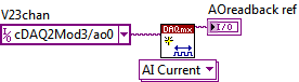
By using the technique described in the example given (DAQmx_Read_Output_Internal_Channels.vi) I'm reading a current area of OCCUPANCY on my compactDAQ cDAQ-9174 with a module of analog output current OR-9265.
The output channel is created in MAX and my vi can write values to him without problems
But when I try to create an analog input channel to read the output, an error occurs.
What I am doing wrong?
This is not supported by my hardware?
Or is the example given in the above incorrect link?
The example is 10 years old. Maybe, it does not work in LV2013.
Hi Jocker,
The link was not attached to your message, but I guess that's it: http://digital.ni.com/public.nsf/allkb/CB86B3B174763C3E86256FFD007A2511 as there the example of vi you mention.
The error you are getting is due to the use of the channel for analog output and trying to configure the task as a task of entry. You must use _aoX_vs_aognd as the channel of the task rather than on the output channel. This compares to the ground for the analog output values.
The NI 9265 is not on the list of the C Series modules that have internal channels:
So I guess that the module is not able to compare its output to ground. He would appear in the dropdown of the channel names if available.
Pete
Applications Engineer OR
-
NI USB - 6212 BNC analog input impedance matching
I just ordered a case NOR USB - 6212 BNC DAQ (should be delivered soon). I want to use to measure HV signals using a probe of high voltage of 1/1000 I have.
Now, datasheet of the probe (not a lot of info) says it has an impedance imput 100MOhm. I suppose that it consists of a simple resisitve divider, and if the ratio is 1/1000, I wait so to have a 99.9MOhm resistance in series with a 0.1MOhm resistance. However, the data sheet also specify that the probe is designed to be connected to an oscilloscope with an impedance of 1MOhm. As this input impedance is very low compared to the low value of the separator of resistance resistance, so I guess that the real resistance at the level of the sensor values 99.9MOhm and 0.11MOhm (to obtain the 0.99 and 0.1MOhm when it is connected to the oscilloscope for 1mW).
Therefore, given that the impedance of the USB-6212 according to the datasheet, the analog input is > 10GOhm, I expect to measure higher to true alternative voltages when connected to the acquisition of data from 10%. This assumption has a meaning?
What would be the best way to get around this? Do a calibration and correct the values acquired in LabVIEW code? Or should I add precision 1MOhm resistance at the same time to the acquisition of input data to decrease its resistance to entry to the value expected by the probe?
Thanks for your help!
Since you have a range of 1000: 1 I guess you also need bandwidth (I have a TEK 6015 A
 ), so you need based on the impedance input, a complex value, means he must not only watch but also the ability to input resistance (1 M). demarcation of the field probes have usually some elements of toppings to match the probe and the input scope. RTFM of the help of the probe
BUT a more serious point is that with your probe, you have a very high resistance. And if you look in the specification of the 6212 you will find on page 2 by mistake ppm in logarithmic scale graph! and even 100 k source impedance it not shown.
So I'm afraid that a simple 1 M on the DAQ entry can work if you're only measuring DC, and only if you use a channel on the acquisition of data. A workaround is an amplifier separate buffer with an impedance of good entry corresponding to the specification of your probe and a low output impedance.
-
USB-6212: software problem timed task of analog input
Hi all
I have unexpected behavior using a USB-6212.
The code example shows that when I run in sequence two analog DAQmx to task, material entry first a timed, the second software timed, it happens that the first readings of data are all wrong and have the same value for all channels.
The labour code is the following:
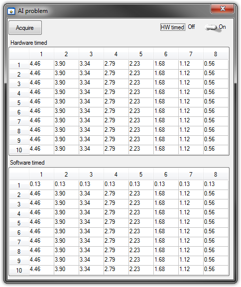
   GetCtrlVal(panelHandle, PANEL_HW, &Switch);

    if (Switch) {
//
// First Task: read 10 rows of values with hardware timing
//
        DAQmxCreateTask("", &htAI);
        DAQmxCreateAIVoltageChan (htAI, MX_DEV_AI, "", DAQmx_Val_NRSE, -10.0, 10.0, DAQmx_Val_Volts, "");
        DAQmxCfgSampClkTiming(htAI,"", SAMPLE_RATE, DAQmx_Val_Rising, DAQmx_Val_ContSamps, 1000);
        DAQmxRegisterEveryNSamplesEvent (htAI, DAQmx_Val_Acquired_Into_Buffer, SAMPLE_RATE, 0, RefreshCB, NULL);
        DAQmxStartTask(htAI);
            Delay(1.0);

        DAQmxStopTask(htAI);
        DAQmxClearTask(htAI);
    }
//
// Second Task:read 10 rows of values with software timing
//
    DAQmxCreateTask("", &htAI);
        DAQmxCreateAIVoltageChan(htAI, MX_DEV_AI, "", DAQmx_Val_NRSE, -10.0, 10.0, DAQmx_Val_Volts, "");
        DAQmxStartTask(htAI);

    for (i=1; i<=10; i++) {
        DAQmxReadAnalogF64(htAI, 1.0, 10.0, DAQmx_Val_GroupByChannel, AcqVoltRow, HW_AI_CHANNELS, &read, 0);
        SetTableCellRangeVals (panelHandle,PANEL_SOFT, MakeRect(i, 1, 1, HW_AI_CHANNELS), AcqVoltRow, VAL_ROW_MAJOR);
        Delay(0.1);
    }
    DAQmxStopTask(htAI);
    DAQmxClearTask(htAI);
A picture is worth a thousand words: analog inputs have been connected to a network of resistance have known values.
The upper table contains timed material acquisitions, the lower the software timed readings... as you can see it the first line is the set of values of 0.13, totally wrong
If the task of timed acquisition of software runs without the earlier (in my demo, that this can be achieved by the switch at the top right), the readings are correct!
Y at - it something I am doing wrong?
I also tried to run the program on USB-6009, but it seems to work properly.
[LabWindows/CVI 2010 SP1 - driver OR-DAQmx 9.4 - Windows 7 x 64]
This problem was corrected by NOR-DAQmx 9.5
324044 NOR USB-621 x task HAVE request returns incorrect data after erasing a task HAVE stamped
-
Medium-sized dynamic data analog input read DAQmx read
Hi, I'm new to labview. Is there an easy way to index using the dynamics of data returned by a readout DAQmx x samples to calculate a moving average? My thought was to read the analog input for X samples pump with the data in another loop through the data, but I can't quite understand how index using the returned data set to extract the measurement value double returned for each sample.
Any ideas on that?
Thank you...
If you get a type of waveform data, why did you ask on dynamic data? No, of course not would you use the conversion of dynamic data on a waveform.
If you want only one channel, then your DAQmx Read could be changed to 1Chan NSamp. If your channel list only has one channel, you will get a table 1 d with a single element that can be indexed. To get the average of a waveform use the statistical function with the waveform. You use the average Point by Point, and not the average function that has a table for an entry.
Make sure you always have context-sensitive help on. You can avoid many of these rookie mistakes simple.
-
Oscillator and analog input (NI 9205) in parallel?
I have a module of analog inputs NI 9205. I want to check the read values are ok and that this purchase is fast enough (because I have some values altogether making strides in 1ms and I don't know if this fits the material real signal).
That's why I put an oscilloscope in parallel with an analog input and my source of voltage (low impedance). But then the read values are not correct (practically 0). I changed the impedance of the oscilloscope to 50 ohms to 1mW, but it's always the same. The values on the oscilloscope are correct.
Is it possible to have an oscilloscope in parallel with an analog input?
I'm not the best expert in electricity...
Thanks for your reply.
In fact, it worked. I measured voltage wrong because all the reasons for the BNC connection to the oscilloscope are connected. I keep this in mind...

Maybe you are looking for
-
want to 700-215: Add drive hard 4th envy 700-215
You want to add a disk hard 4th envy 700-215. There are only 4 connections on the motherboard sata, one is used by the dvd and then the other o\are 3 used by the hds. Is there a method to add another connection sata for the 4th disc, or is the choic
-
Error - 12 during the construction of facility LV2012
When I Isaiah to compile a setup in the menu project I get immediately error - 12. (see attachment) This has happened on several different projects. I can make one. EXE, file Zip and distribution build but not Installer. I read the "why my Distributi
-
I have windows xp when I reboot go to debug, how to solve this problem, please help.
After the reboot to start debugging and stop and do this message of line las: stop: 0x000007E, (0xC000005, 0 x 0000000, 0xBA5077C8, 0XBA5074c) I have windows XP on ACER laptop travel companion. Please some guys could help me. Thank U.
-
Z3 on WCH10 cannot load, what is the problem?
somehow my z3 won't charge on wch10, I tried all the possible positions on the wch10, still no contact. wch10 itself flashes twice if he plugged into the net. is this a known issue?
-
ReferenceError: Can't find variable: blackberry
When I try to run this code: blackberry.pim.contacts.find(contactFields, null, onFindSuccess, onFindError); on the device, I got error in Web Inspector: ReferenceError: Can't find variable: blackberry Could someone help me? Thanks in advance