average timed sub vi
I train using the sensor data by sending one under vi I created, which will add a table in the sub vi every second, and then at the end of the set time out on average during this period and reset the table. For some readon some of my data values are coming very badly. Could there be something wrong with this vi? Specifically, I wonder if there is a problem with persistent data in the sub table vi... I'm under LabVIEW 8.5
You should be Subvi to be reentrant. Go to the properties of VI-> execution. There is a check mark there for reentrancy. If you choose, you want to pre-allocate clone for each instance.
What this will do, is that each call to the Subvi will have its own memory space. He is currently sharing space and therefore your averages are getting all foires.
I would recommend visiting the Journal of ground LabVIEW because there are some good articles on this subject this year.
Tags: NI Software
Similar Questions
-
Hello
I am collected signals every 200 ms for 5 minutes on average. I already know how to install a loop and get an average of iternations N, but that is basically just noise filtering... I want to take all values over 5 minutes and then on average to get an average 5 min my signal.
What I'm trying to do in the end, it's to get an average 5 min my signal and use a shift register to hold that the average value to use as my 'initial value' or the start-up pressure in my case. I then use this starting as pressure and calculate the increase in pressure per cent over time. After say 30% increase in the average pressure of 5 min I run a sequence of cleaning the filter and repeat the process and get another 5 min way to use my new initial value. Basically, I know how to do all this, but I am just hurt with averaging values... and I tried all sorts of things to the table and looked at examples for hours and still could not understand...
First of all, I'm trying to make it work on a simple labview (attached image) program, and once I figured out I'm going to work on my actual program...
I'm using labview 8...
I thought I saved it for version 8.0, but maybe not. Try this one. I think it is close to what you are looking for.
-
type 'whitenoisesignal' is undefined
Hi all
I am learning the use of controls of mstudio in vb.net.i has presented a request to learn the work of grapg the form of wave and evaluate.
to do this, I followed all the steps perfectly as shown in this video "https://ni.adobeconnect.com/_a56821929/p51878979/?launcher=false&fcsContent=true&pbMode=normal".
He still gives 2 errors
(a) type 'WhiteNoiseSignal' is undefined
(b) the name 'Statistics' is not declared
This is my code:
Private Sub Button1_Click(ByVal sender As System.Object, ByVal e As System.EventArgs) Handles Button1.Click
' Declare and initialize an instance of WhiteNoiseSignal.
WhiteNoise As New WhiteNoiseSignal() Dim
'Store the data generated in a double table named data.
Dim data As Double() = whiteNoise.Generate (1000.0, 256)
' Using the method of foot to plot the data.
Plot.PlotY (data)
' The average method to calculate the average data.
Dim average As Double = Statistics.Mean (data)
'Display the average on the gauge.
Gauge.Value = average
End Suband when I am debugging it gives project.exe message is missing.
Please help me
Hello
You must set a reference to the NationalIntruments.Analysis class
The statistics are in NationalIntruments.Analysis.Math
WhiteNoiseSignal is in NationalIntruments.Analysis.SignalGeneration
Curt
-
Hello
I try to have a vi that receives an array of file, and then built the sup boards (according to the FPS/mid-range everything), then take the average, detects the difference between each data point and count the number of times where the difference is greater than the threshold. Please see the attached file - my block diagram.
At this point, the vi is running but the is a bug in the code that I can't find :-(.
When I run it on a counter of data sample returned ~ 350 where it suppose to be only 3.
I will appreciate if you can take a look.
Thank you
PS.
I am happy to download the vi and an example of data file if necessary.
simply_me,
You take a subset of the table, get the average which seems ok. But then understand you the difference between the average and all you started with instead of the subset of the array that allowing you to calculate the average. Guess you have to do this.

-
PCI6251: How to reduce widely AO size FIFO or Disable AO FIFO in AO HW timed DMA operation?
I took aoex5 as a basis for the generation of signals timing hw AO0 DMA and it works well in my setup. At the same time two signals which depend on AO0 are measured to AI0/AI1 by hw-timed-DMA mode maximum rate (500 ksps / s) and it works as well.
My goal is to apply a positive feedback mathematically AI1 to AO0 nationwide, and the easy way would be to change the values in the channel DMA AO AO rate on the fly, by reading the latest channel DMA AI values. The processor speed and the DMA space would be quite sufficient. The problem is that the CED are charged by means of a FIFO buffer that has a size of 8192 samples for my Board, and so to change a value in the buffer DMA would have no effect on the output DAC.
I tried to simply disable the buffer FIFO of AO by setting AO_FIFO_Enable to 0, but it disabled the generation of signals AO together. Is there a way to disable AO FIFO and leave the DAC values directly from the buffer DMA? Or can I reduce the size of the FIFO AO programmatically to a minimum number of samples (2-16)? I could survive with a little latency induced by a small FIFO buffer, because I can compensate for this by changing the rate AO on the fly as well.
I know, I use timed by the sw operations to achieve the goal, but I assume that AO DMA without FIFO operation would give me a lower latency of feedback.
Thank you very much in advance for any helpful ideas.
Best regards
Rolf
Hello Joe!
I decided to start my experiments with the generation of signals AO0 clocked by sw.
In order to test I put AI_Bypass_Cal_Sel_Pos-7 and AO_Bypass_AO_Cal_Sel to 0, while the generated signal is directly available on AI0. I was programmed to the maximum rate of dual channel (500 ksps / s) in a linear DMA buffer of 128 MB. To AO, I programmed a triangle (ramp-up/down) for a period of 2 V which is represented by 12975 AO samples.
A tight loop software added an average across the last 4 Readings found in the DMA buffer to the AO value at the next exit, and once the LSB of the gross sample of AO changes, it is written to the DAC by Board-> DAC_Direct_Data [0] .writeRegister (Uc).
I did tests with different speeds of scanning voltage from 0,1 up to 250 V/s. The AO to 250 V/s sampling rate was 1.6 MECH. / s. The deviation of the curve at the higher rate to the lowest rate is only 0.1%.
Attached to this message you will find a diagram showing the magnification of the curves around the tip of the triangle. The Green curves taken at 100 and 250 V/s. Red to yellow to 0.1, 1 and 10 V/s. There are very low phase shift of 0.1% to scan rate of very hight perhaps due to the latency of your comments.
Honestly 1.6 MECH. / s mode AO NI by sw including the algorithm of feedback far exceeds the expectations and I must admit, I am perfectly satisfied with this result. Sorry, Joe, but with that, I lost the inspiration to try out your suggestions, reducing the size of AO DMA buffer and change the FIFO AO mode. Anyway, thanks a lot for your answers.
Best regards
Rolf
-
Average displacement Subvi does not refresh the data in time real host VI
Hello!
I time real host VI that has evaluate the NI 9215 cRIO block data 9073. He takes analog data and calculates the phase shift. It works well with the connected equipment and displays the results. I need to get the moving average value of phase shift, so I add moving average Subvi, where main VI entries - new value (phase shift measured) and ms and output - average value of travel time. When I run real time host VI it gives me a single data and stop get new data from Subvi. It refreshes not even values measured in real time. So the problem somewhere in the accommodation, with sub - VI. How it can be solved? How can I get real host VI with the moving average value of Subvi update running time?
Thank you.
Your problem is that you have a loop that runs until you press the Stop button inside your Subvi. If you try to use a Global Variable that is functional, you have a few things wrong.
1. the loop should run only once. A TRUE to the conditional stay Terminal wire.
2. the shift register cannot be initialized. That is how he can keep the old elements in a story. Use a first call? with a case structure so that you only initialize the table of history inside the loop on the first time the VI is called.
But if you really want to make your life easier, just use the PtByPt.vi mean. NOR did all the work for you.
-
Moving average filter w / continuous data acquisition
I'm looking to filter multiple signals of noisey. I am currently using a NI9203 w / a cDAQ-9174 sampling to 1000 Hz. I use DAQmx vi to start the task and acquire the signal. I tried using coefficients.vi smoothing filter combined with IIF filter.vi (Avg.png movement) it seems to work for simulated signals and recorded data. However, when I try to use this configuration for an average of real time it cut everything just all signals to zero. I looked into the use of shift registers, but to get the necessary result, it seems that I have to use hundreds of items.
In the end, I'm trying to filter the signal to get a constant more of reading for the user. For example during operation, the user needs to review the current state of the values in real time. It's currently difficult when the noise indicates the values of +/-100 changing every 100ms.
For any help or suggestion would be appreciated, thanks in advance.
Thank you all for the help and advice. I have attached the vi that I used to solve the problem, one of my major problems was not timing DAQmx using. Attaché in 2012 and 2013.
-
Questions about an average of response spectrum and frequency of feeding mode.
Hello
I have a few questions about an average of mode. When I generate a sinusoidal signal from one output to two input channels channel to see if my DAQ card works well and vector averaged in the power spectrum for DFT, the amplitudes was different from the previous one of the amplitude, which was supposed to be 1 v peak. They range from 0.5 v to 0.6 v peak. When the calculation of the average model is RMS, the amplitudes were close to 1. I wonder what are the fomulas of RMS and average vector. Does that mean that I could not accurate if I use an average of vector? In a time of frequency response, why I coherences of difference and the amplitudes using the vector and the mean quadratic value?
Thank you
Ningyu
rico1985,
The differences in modes of generation are as they sound: 1 sample output only a sample writing, N samples will be released however many samples configure you for each entry, and the continuous samples released samples continuously until a specified user action happens (you press the stop button or a logic that you created gets fulfulled). The range of Signal output allows you to set a ceiling high and low level of your output signal and it only affects the quality keeping in this beach. Timing to set a deadline for the time between the acquisition of the sample. If a new sample becomes unavailable before the timeout setting, you will get an error. This is useful for looking at a network, because if the network goes down and you stop getting data from a machine and then you would like to know about it. I point you to those videos that are short tutorials on how to make the most of these actions in SignalExpress.The SignalExpress 3.0 Help file is also your first point of contact for all your questions on getting started. These two resources should get you up and running in SignalExpress in no time. (either by the way all your questions answered using these resources) Bravo!
-
Detect the PEAK, mount and average
I use a loop in LabVIEW 8.5 to capture the signals emitted continuously by a card, peak detector.VI is used to detect the signal peaks, then fit.VI nonlinear curve is used to climb the summits, signal now capture, detection of peaks, mount and display pics are all works very well permanently, but there are still some problems annoying me.
1. the received signals is not very stable, so editing results expected on average for 100 times, then how can I averaged the results of fitting on the condition that the capture of signal is not interrupted, this is the time loop does not stop, when the average is made this time, average is reset for the next 100 fitting results can be average again?
2. There is another way, that's 100 results of fitting is automatically saved to excel, then the results is an average manually in excel, then how to store results like this: the first 100 results of connection are stored in an excel file and the next 100 results for other excel connector or they are stored in an excell , but in different columns? Of course the thses are subject to the capture of signal is not interrupted.
3. There is a threshold for the detector.VI peak, but the captured signals entry isn't very stable, so the number of peaks detected is not the same every time, like this time, the number of vertices is 40, next will be 39, this will affect the results of fitting slightly, then how do to detect the same number of vertices every time such as the number is 40 each time?Any advice will be appreciated!
Maybe the pic attached detect.vi 'test' can help you. "medium signal.vi" is a sub VI on average the signal in a way online.
There are three methods using the input signal:
1. no average.
2. average exponential.
3. linear average.
Your problem is when the input signal is damaged by some noise, and you want the input signal before the detection of peaks on average. I use white noise to simulate a noisy environment.
By default, the average mode is 'Linear', and the number of averages is 50. The more averages, the best on the result, but more time to update.
Swith mode between 'Linear' and 'No way' to compare the difference before average and average.
Average exponential is not appropriate in your case.
Let me know if it works for you.
-
Get a precise timing in a C++ shared library in VxWorks
Hello world
I am developing a shared library for VxWorks for my compactRio access a «no massive strorage» usb device
I work with gcc (see develop shared libraries for the cRIO-901 x and other targets of VxWorks for more details).
The usb part works fine, but I now have to obtain a precise timing in one c++ shared library functions. I tried the functions clockLib (e.g. clock_gettime () - see page 8 of the http://www-ad.fnal.gov/controls/micro_p/manuals/vxworks_application_api_reference_6.6.pdf for more details), but they seem to have a resolution of 1 ms, which is not enough for me.
There is a clock source faster on the cRio (at least 1 Mhz, one used for timed loops) but I do not know if such a source could be used in a shared library. If so, anyone knows what are the functions of call?
Thank you very much
Martin
OK, I thought about it. These functions are exported as C functions, so you should use extern 'C' instead of extern just by itself, as I did originally. Once I did, I was able to compile the following code in its own. File AND it works fine:
#include
extern 'C' unsigned long niTimestamp32();extern 'C' Sub TimeTest()
{
unsigned long ts = niTimestamp32();
printf ("niTimestamp32 () = 0x%08X\n", ts ");
}Good luck and let me know if you have any problems and more.
-
Model in the loop timed While the elapsed time
Hello NOR community,
I'm trying to use a while loop timed to run controller simulated for a mechanical system test. I need the time loop to run at an even 50 Hz to simulate the controller that will eventually drive the mechanical system. To check the speed at which the loop runs, I made a VI that gets a value from each loop clock and subtracts the value of the clock of the current iteration of the value of the clock of the previous iteration. I have eliminated all other codes this VI except for the recovery of the clock, to ensure that no problem with another code in VI. I find that the time between iterations is not constant, but it is consistent. In other words, the elapsed time can change at each loop, but it changes according to a specific model, such that the average elapsed time is equal to the value that I use for the timed loop. The loop will run faster than posed for several cycles, then slow down during a cycle even at the same time. Here are some examples:
Running at 5 Hz: elapsed switches schedules between 0.203125 and 0,187500 seconds
Clocked at 8 Hz: time is constantly 0.125 seconds.
Operating at 10 Hz: elapsed switches schedules between 0,109375 and 0,093750 seconds
By examining the differences between elapsed time and the stability of the 8 Hz setting, it seems that there is a minimum time of 0,015625 seconds (64 Hz) division. It is much worse than the 1ms accuracy claimed in documentation. This could be the cause?
I am running Windows XP with LabVIEW version 8.5.1 and have observed this behavior on several computers with different screws
Thank you!
Erik
Your problem is the function that you use to get the current time. It's just the time of the Windows clock which has a resolution of 16 msec.
You must use the function of number of cycles as Jarle has pointed out.
-
Most of the machine control software I design have the following structure:
1. There's a HAND that takes place inside a TIMED LOOP with synchronization of 50ms and priority of 100. His only job is to read / write data from / to DAQMx IO cards.
2. the MAJOR can call several SUBs based on the choice of the user, and once a submarine is called FP MAIN is closed and the FP SUB opens. All submarines have a States Queued Machine running within a TIMED LOOP with 50ms timing but with priority to 50.
3. data transfer between HAND / SUB is through function globals - there are many of them based on past data.
4. all woks fine so far. No need to any RTOS. and platform of WIN7 is alomost standard. I even ran with a timing of 20ms without anything crashing...
Problem: When there are a lot of file i/o operations in a SUB partciluar, then I have the chance to see several missed iterations. Perhaps the TIMED LOOP is hogging resources.
What I want to do: convert both TIMED in asnd SUB HAND loops simple while loops. But I am concerned by the priority - since the MAIN interacts with HW there priority. But with LOOP WHILE how can I ensure this?
Or is there any replacement / effective way of doing what I do now?
Rama wrote:
.... FGV should be thrown out the window...

Well used for a while, based on many articles in the KB. One of them is locked... and it does not represent the engine of the Action or of the FGV as a villain to avoid.
The driving force is one of the largest buildings in LabVIEW. The FGV who does nothing but Get and Set (or writing and reading) is useless and a waste of resources. Why? It does nothing to fix possible race conditions (does not protect critical sections) and it is much slower than just using a global variable. See this example I put in place to see what I mean: an overview of the race Conditions.
Rama wrote:
So in the sample that I had attached, what do you think would happen if I just replaced the two loops with the SAME timed in MAIN and SUB wait value ms. is there a work order then?
When things are at the same time, there is no such thing as the order of execution. But as I said, it seems that your loop is quite slow, so it's something I would not worry. Just make sure that you do not have a loop that uses all the CPU.
-
With an average of values table in a 2D space circular
I'm trying to average the temperature values in a table 2D, in rectangular coordinates, on a circular area. Is there a sub-table function that works in polar coordinates, that I could use? Any suggestion would be appreciated.
-
Q on the timing in VI and Subvi loops
Well, it's probably something pretty much anyone here can answer immediately, but it seems to be a black hole in my knowledge of LabVIEW and has been bothering me for some time.
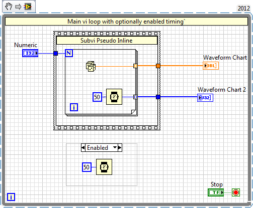
I certainly appreciate that if you have a VI with a loop with no timing information, as soon as possible, it will loop hogging CPU resources, leading to Bad Things (TM). However, if you have a VI with a loop containing a Subvi with a second loop which calendar information (for example, returning a line series fast @ 1ms), do you also have a timer outdoors VI, or not? I almost always err on the side of caution and put one in, but if it is redundant, I would naturally rather let.
Thanks in advance,
Cameron
An interesting question that deserves an answer by a simple example. So I whipped one to demonstrate

I took a minimallist approach! Suppose that this snippette represents a simple sub - vi with a loop that contains some time, and a caller who is not sure if it's a greedy loop or not. (A bajillion other examples might exist, but this one is so so good, very clear)
A simple run and inspection of the calendar table will prove that the delay in the outer loop has no effect loop performance as long as they delay is less than or equal to the total for loop takes. Go ahead and activate and deactivate the box containing all buckle in late. You will not see a difference in the timing table. In other words - the subvi provides all the "Pacing" which requires the module and the while loop is not greedy.
HOWEVER: now that you've proven the while loop is not greedy 'digital' in the value = 0 and try again

-
Average for a quarter and the grand total amount
Hi all
I have a report (PivotTable) in which I view information about sales. I have category, subcategory in the rows. Quarter of the year in the columns. Sales are loaded at the day level in the fact table. My report must indicate the average quarterly sales. That is to say that all sales per month should be added to the top and sales 3 months should be on average to get the average of quarterly sales. We must show the total sales for each category sub. We must also show the % of sales for each subcategory with a category.
I did the following,
1. the aggregation of the column in the SPR Sales is basically
2. in the report, I shot months in the criteria and which excluded the pivot
3. I changed the aggregation (for total rum) for the SUM of criteria-> the column formula
4. I changed the AVG aggregation to view measures pivot
5. I have reproduced the measure to display the percentage of its sales
6. I enabled total in the lines.
Everything works well except the value of the subtotal of sales which gives me the average of subcategories at the level of the category, instead of this, it must be a sum. The % of total is correct where he gives 100% for each category
Please help me reach the sum to the total sub level
Thank you!
Concerning
Deepak
Hey, I just fixed the problem myself. The solution was to write the formula as AVG (sales per quarter, category, subcategory), then change the rule of the aggregation in short.
Maybe you are looking for
-
Satellite L650 - 12K - restore the factory with Windows password settings?
Hello Today I received my new Toshiba Satellite L650 - 12K. I went through the process of "first use" and put in place my name of user and password Windows 7 etc. However, after a reboot, when I tried to enter my password to connect to Windows, it sa
-
Upgrade from Vista Home Premium to Vista Ultimate
This is a question for someone at Toshiba: I have a copy of the Windows Vista Ultimate DVD (given a conference I attended) and I would like to use it to upgrade my Satellite laptop to Windows Vista Ultimate Edition. This morning I did a clean install
-
Hello everyone, I need to understand the algorithm of automatic scaling in DIAdem for illustrations. Or at least if I put a chart on Autoscale read min max and Tick-Step. is this possible? I need that for my reports that are very automatisated and ac
-
OMG... I'm so frustrated I'm trying to "burn" a CD - but I don't know how to get all the songs I want my music files for windows media player... sometimes I try to drag and drop - it does not work. I'll also to the song to find a file 'my documents'
-
How to incorporate the owner information in the rocket?
One day, a friend of mine came across a Sansa Clip unmarked abandoned (accidentally deleted, I'd bet) on the street. There was absolutely no indication of the owner of the player, even if it is clear that the music contained in was rather horrible to