bandpass filter
Hello.
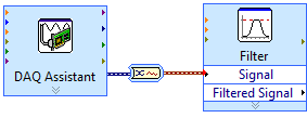
I am applying a bandpass filter, blocking the frequencies below 0.1 Hz and above 5 Hz with sampling frequency of 50F - 3. I put it in place using a butterworkh as shown in attached but nothing comes out, my graph and table are empty. I have the filter correctly configured or is there another step? Should I use a different filter block?
Thank you very much
Jim.
You did not file your file text, but from your diagram, I suspect an incompatibility between your sampling frequency (50 mHz-> 20 sec period) and your loop times (wait.. value 5 msec). Try to increase your sampling rate or your loop delay.
Ben
Tags: NI Software
Similar Questions
-
bandpass filter does nothing for data...
Hello world!
I intend to apply a bandpass filter (Butterworth filter, 3rd degree) for my data to cut highy and low frequencies (from 1.2 MHz to 2.2 MHz). I've attached a picture of my vi. But what I get after filtering is the same as raw data.
When I'm wrong?
Thaks for all help.
yolobia
It is difficult to tell from a photo.
Most likely, the problem is due to not to provide timing information to the filter VI. When you convert the 2D dynamic data table, nothing specifies the sampling frequency.
Lynn
-
Hello
Is there a way to (bandpass) filter complex signals in Labview? I Googled it but I don't seem to find a way to filter complex signals (a + i * b).
Edit: The block of normal bandpass filter will not work because it does not accept the complex entries
Divide into re / im, filter individually, recombine.
-
the power of the spectrum graph and butterworth filter
Hello
I am beginner in labview, I want to see the power spectrum of the sound samples, I want to see if there is any reason in these samples.
I use spectral measure, and then I filtered with butterworth filter samples. For output I using waveform graphs.
Before filtering the signal, I'm in the x axis of the graph between 0-22500 and the data mostly in 0-2500.
I've tried to filter using these values (fs = 1000 Hz, 0.125 hz = fl and fh = 500 hz) and the graphics almost the same thing but the axis of the graph is between 0-0, 5.
issues related to the:
What is the x axis properties? Why is different, but the graphics are the same?
Make the mistake with the program?
Hi Limavolt,
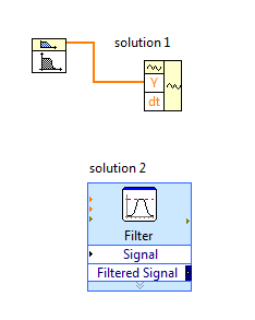
You have a problem with the bandpass filter VI, this VI generates only the signal of value i.e. table DBL. The signal is a cluster.
solution 1: you need to calculate 'dt' using the sampling frequency and use VI waveform construction to generate a signal's own scaling.
Normally, dt = sampling frequency/No. samples
Solution 2: replace the VI butterworth filter with filter VI express, this will produce signal without scaling.
-
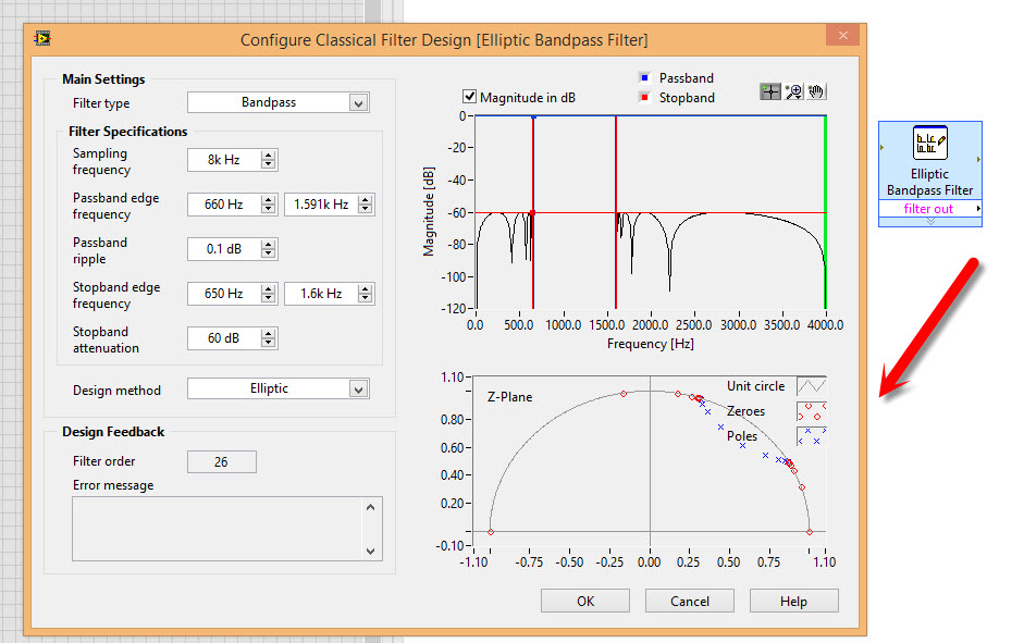
How to apply the classic filter Design Express VI
I use the digital classic filter Design VI design a bandpass filter (try to follow this example http://www.ni.com/white-paper/4460/en/), but then I can't locate
Filter Express VI to use the filter
The express VI filter comes with the LabVIEW base development system. It is found in the range of functions under Express > Signal Analysis > filter. Have you checked here?
-
How to design a digital filter without addon Kit
Hello
I want to design a bandpass filter. Original signal is in analog form, ADC is used to convert the entries in the data digital n vice versa at the end of the output. How in labview 8.5 without addon Toolkit. Secondly how do I check the response of the filter according to these digital data, because by default, it gives the IMPULSE response, so how his will handle digital data...
Thank you!!
In the impulse response 1 sample is greater than zero, the rest is equal to zero. For the step response values are zero before the stage and not zero after the stage. To do this just make a table with the signal you want to use. But the table must be long enough to cover your analysis in the time domain. For example. I'm working now with digital phase sensitive detector. For this I use a sampling rate of 20 kHz, one of the last steps is an order of 3 Hz 20 filter low pass. To test the response of this filter, I needed at least 12 seconds of data. If the table that contains the data was 20000 * 12 samples
-
Hi, I'm new to Labview. I want to put in place the receivers (simulation of) homodyne and heterodyne receiver in labview and want to get the SNR and BER plot. I can do in Labview.
The following elements are involved in these Receivers: low noise amplifier (LNA), mixers, bandpass filter, lowpass filter, the converter sampling analog-to-digital is to say and quantification
Hello
There is no built-in feature in LabVIEW that would directly simulate these components. However, if you know the math behind them, you could write code yourself to simulate these parts.
You can also look on the Modulation Toolkit for some of you said it the signal processing:
http://sine.NI.com/NIPs/CDs/view/p/lang/en/NID/210568
Kind regards
-
Hello!
I'm in the quest to replace some aging PCI-5640R. I am currently using as a portable-Journal data solution, mounted in a Magma Expresscard to PCI box with a laptop. As a reference of the time, I use a Symmetricom XLi.
The equipment is dependent on the sampling finished a set of samples once a trigger signal goes high and also receive antenna azimuth information using two lines PFI more. The signal is sampled at IF, 30 MHz, and the signal is less than 5 MHz bandwidth.
Now, I started watching the Ettus X 301 with a GPS OCXO and MXI-express interface which should be the same as the USRP-295xR NI. It is available as device NI RIO with three different front ends, unfortunately, none of them work at 30 MHz.
Q-1: Ettus has the front-end 'BasicRX', but it is only considered compatible with LabVIEW driver and not necessarily with the RIO. Is the front-end BasicRX usable with the USRP - 295XR RIO and MXI-interface with LabVIEW FPGA? Should I just avoid trying tune the nonexistent LO? As long as he gives me data, I can live with some error messages during the Setup...
It's the best solution for me, but if it is absolutely impossible, I have a few questions:
Q-2: information on the front end are really rare in the pages Web OR both Ettus, but the WBX is listed up to 50 MHz frequency, to have a filter of low pass of bandwidth of 40 MHz to I and Q. This should mean a total of 80 MHz of bandwidth with I and combined Q,-40 to 40 MHz. Why did the bandwidth to Web pages as OR listed being "40 MHz bandwidth in real time", if the low pass filter of the WBX is 40 MHz in I and Q? Not the band total bandwidth or 80 MHz?
Q-3: assuming a bandwidth-40 to 40 MHz: could I put the WBX LO at 50 MHz, be tuned to the frequencies from 30 MHz to 20 MHz signal,-20 MHz and use a bandpass filter to the FPGA to extract the new signals and remove all other signals?
Q 4: I tried to start a FPGA project in LabVIEW and add the x 301/294xR/295xR as a target. Data clock is locked to 120 MHz, which I guess means he will receive no data to 120MS/s IQ? The x 301 Ettus is listed as provide data of the ADC to the FPGA at a rate of 200 ms/s, could someone explain to me why, OR USRP RIO expects only database 120MS/s?
Hi Idar,
Yes, you should be able to put the basics on your X 310/USRP RIO and use LabVIEW FPGA to receive 120 MECH. / s of the DACs. The example I posted is in fact not for the precompiled file bit. The example I posted is for LabVIEW FPGA, which allows you to add the IP address for the FPGA. There is a sample project that comes with LabVIEW FPGA which is the recommended starting point to build your FPGA application. The sample project has all the configuration set up as well as broadcast continuously and pads/FIFOs in the FPGA and examples for synchronization. There are comments in the code example that show where he must add your own blocks of property intellectual as a filter and decimater you mentioned. The PDF I posted shows what changes you must make to this sample project using the Remora Basic/LF.
I would like to know if I'm not explaining this clearly, or if you have any questions, I'd be happy to help you!
-
locking using NI USB-6251 amplifier
Hi all:
I'm in the very initial stages of development of spectroscopy (FMS) frequency modulation experience on my set-up of already existing absorption spectroscopy. I know that I'll need an amplifier to lock to select the signal at a specific frequency. I already have an acquisition card of NI USB-6251 data which works very well and I've used for my experiments of absorption spectroscopy. I was wondering if there is a way to create an amplifier to locking vi which uses the NI USB 6251 casing and would do what I need for my FMS experience. I try to avoid buying another instrument, if I do not need.
Anyone who is familiar with amplifier locking vi and see if I can put it with my USB NI 6251? Thank you!
Alfredo
Herea link to the use of an amplifier to locking using LabVIEW. However these specific VI were designed to use our acquiring dynamic signals of maps that isn't the 6251. You can try using a simple bandpass filter in the software, but it is certainly not an ideal situation in any stretch of the imagination. But with only the 6251, it is certainly an option.
Kind regards
Brian P
-
How to implement point filters fixed for FPGA
Hello!
I am applying the bandpass filter Butterworth for FPGA.
I managed to develop filters of fixed point that suits my needs, but I don't know how to implement on a table in a project after the FPGA code generation. I tried to understand it in the examples, but I was not very successful.
My time to finish what runs, any help would be really appreciated...
Any suggestions?... some examples?
Thanks in advance
I've already done that and solved the problem.
In any case thank you and have a nice day
Ljubica
-
I am trying to remotely control a bandpass filter from K & L. Their programming manual is very vague, and I'm new to these types of devices. Their manual suggests that orders are simply strings of bits or bytes.
To obtain the status, byte 0 is set to 1 decimal place. The order is byte 1 and decimal value 8. Byte 2 is the size command, and then assign a decimal 32. Byte 3 is set to 0. So, I guess I want to transmit a command that is formatted as follows:
00000001000000100010000000000000CR
The box does not respond, and the connection times out.
I even tried to hex
01082000CR
And I didn't recover. Does anyone have experience with Bandpass Filters K & L Microwave LPI who might be able to put me on the right track?
Thank you!
Do you have a manual of K & L? I checked their Web site, but without knowing the exact model number, I couldn't find 'generic' information about their tunable filters. Looks like your best bet (unless one of us has direct experience) is to contact K & L for more information.
Bob Schor
P.S. - the best way to 'tinker' with a device and try to see what makes it tick is to connect (you don't say what kind of connection you use) to your PC, launch MAX and see if she can 'see' your device (it can be on a port COM or Visa). If so, you can easily send strings to it and see what, if anything, he returned to you. You can easily experiment with end of line characters (does \r, \n, \r\n, \n\r?) and other things.
-
Hello world. Can you please help me with assignment on bandpass filter.
Open the attachment you will find the assignment and the formulas to work with.
Thanks Ed.
Ed,
We do homework for you. As well as being unethical, you don't learn anything.
If you have specific questions about LabVIEW, we can help. For example (and as a tip) the range function & force can be changed so that the upper or lower limit is included or excluded by context-clicking on the icon.
Lynn
-
I generates a white noise of an amplitude of 100. Then I go through a Butterworth bandpass filter with 50 and 150 for the high and low frequency bandpass settings. I find myself with a noise filtered with an amplitude of 20 (more or less).
Why the filter reduces the amplitude of the filtered noise? I noticed that if I increase the range of bandpass parameters (for example, 50 to 500), amplitude reduction is a little less.
I tried other filters and Chebychev seems to be a little better, but it does still not anywhere close to the amplitude of the original signal.
I admit that my knowledge of signal processing is limited. Can someone help me with this problem? Is there a setting that will give me the best results?
Thanks for your replies.
I was under the impression that white noise with an amplitude of 10 when it is passed through a filter would result in filtered amplitude noise 10. But now I see why I was wrong. White noise is the sum of the sine waves of different frequencies; for example, when you filter on certain frequencies, amplitude (which is a sum) will be lower.
And thanks for the tips on the standardization of the amplitude after filtering. That's what I'll do.
David
-
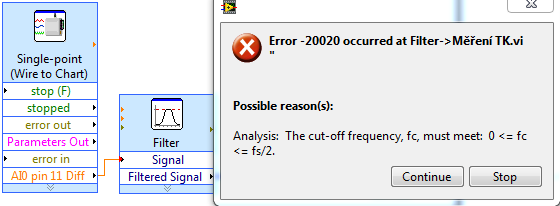
Filtration of single-point data
Hello, I'm trying to filter the data of voltage point unique task, but there is an error of frequency... I have set at 120 Hz sampling frequency and I want bandpass filter for example of 30 to 40 Hz...
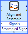
So, where is problem? I tried to use a timed loop or "align and re - sample" sampling frequency, but this filter still does not work...
You know, how to use this filter with single point task? When I do my own filter FIR with the same settings, the results are not same, this is the reason why I want to use this filter.
If I use DAQ Assistant, there is no errors, but I can't use for other reasons (1) I can't use single point and all daq assistant, daq assistant 2) can't do pressure)
These images add nothing to the discussion. If you buy a single point at a time, you have NO frequency and cannot use the normal filter function. Do what I said or use multi-sample reading or single reading point and build the table before making a filter. Best is to use the acquisition of data with several samples.
-
DAQmx data acquisition with persistent error of nyquist
Hi, I created a multi channel data acquisition vi (accelerometer 2 and 1 sound pressure) using models for producer. The vi is attached. Thanks to labview 2011. I get the error of nyquist (2 enclosed) when you make a bandpass filter between 50 to 5000Hz. This happens despite having put my sampling rate to 22050Hz. When I checked the output of wave I noticed that the signal has a dt 1 s. The text output to check the result. I could not understand how this is so since I had set the sample rate to 22 k Hz. Any help will be much appreciated. Thank you.
I would do something like that. You must calculate the dt of the set (with the recipricol) sampling frequency and use to initialize the shift registers. This way you only need to change 1 constant if you need to change your sample rate.

Maybe you are looking for
-
Black screen after login on Satellite L350-20 q (normal mode)
My Satellite L350-20 q running Vista Basic.After the connection, which is normal, I'm going to the arrow then turning to a permanent black screen when I start in normal mode.In safe mode, I have a normal behavior and I can work. No malware present a
-
Tecra S5 does not recognize the SDHC 4 GB micro card
Hello. I have a 4 GB microcard SDHC and the reader of my laptop does not recognize the card... Help. GR Arno
-
Satellite L20-199: System cannot identify WLAN card
Hello I have a L20-199 with LAN wireless satellite. But the system cannot identify the (hardware) wireless network card. Trying to install Intell WLAN driver on the site of Toshiba relevent also impossible to locate a WLAN card. How to install or ide
-
I bought the HP Pavilion g6-2219ss. The OS is Windows 7 Professional 64 bit. Now, the computer does not detect the bluetooth controller, 2 usb 3.0 ports, the SMBus Controller and the PCI controller. USB 3.0: PCI\VEN_8086 & DEV_1E31 & SUBSYS_183F103C
-
Windows error install when you try to delete old programs
I tried to delete the old programs on my laptop HP, Windows Vista... I keep getting an error indicating that the windows service install could not be accessed and that the installer is not installed properly. Help