BarChart in Scattergraph
Hello, I have on my first UI
scattergraph where I draw a few points of some color spaces.
I need
in one configuration a barchart like the following to draw the
raw data of my sensor.
Is it possible to draw a few bars with one
scattergrap?
Hello
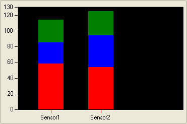
Looks like you want to compare different data (A1, A2, and A3) for multiple sensors (sensor1 and Sensor2). I think that you are looking for something as a stacked chart (see photos). ScatterGraph Studio measure has powerful API that can be used to implement the stacked bar charts.
I just played a little bit the code a little bit that I sent you to get these shots.
(Photo 1)
Code for (1)
using System;
using System.Drawing;
using System.Windows.Forms;
using NationalInstruments.UI;
using NationalInstruments.UI.WindowsForms;namespace WindowsFormsApplication1
{
partial class StackedBarChartInScatterGraphExample: form
{
private static color colorA1 = Color.Red;
private static color colorA2 = Color.Blue;
private static color colorA3 = Color.Green;private static penA1 = new Pen pen (colorA1, 50);
private static penA2 = new Pen pen (colorA2, 50);
private static penA3 = new Pen pen (colorA3, 50);public StackedBarChartInScatterGraphExample()
{
InitializeComponent();
}On the scale of timer generate some data and plot.
private void timer1_Tick (object sender, EventArgs e)
{GenerateDataAndPlot();
}Private Sub GenerateDataAndPlot()
{
Read data from sensor1.
Double dataA1 = GetDataFromSensor();
Double dataA2 = GetDataFromSensor();
Double dataA3 = GetDataFromSensor();Describe X posts. All X values must be same because we want that they in a column.
Double [] sensor1XData = new double [4] {2, 2, 2, 2 ;}Describe Y in a medium stacked column.
A1 data are from 0 to dataA1.
A2 data are dataA1 (data1 + dataA2).
The a3 data of (dataA1 + data2) (dataA1 + dataA2 + dataA3).
Double [] sensor1YData = new double [4] {0, dataA1, dataA1 dataA2, dataA1 + dataA2 + dataA3};scatterGraph1.Plots [0]. PlotXY (sensor1XData, sensor1YData);
Read data from sensor2.
dataA1 = GetDataFromSensor();
dataA2 = GetDataFromSensor();
dataA3 = GetDataFromSensor();Here just shift the column giving another value for X.
Double [] sensor2XData = new double [4] {5, 5, 5, 5};
Double [] sensor2YData = new double [4] {0, dataA1, (dataA1 + dataA2), (dataA1 + dataA2 + dataA3);}scatterGraph1.Plots [1]. PlotXY (sensor2XData, sensor2YData);
}Random r = new Random();
Private double GetDataFromSensor()
{
This is the place where you read the data from the sensor.
return r.NextDouble () * 50 + 25;
}private void scatterGraph1_BeforeDrawPlot (object sender, BeforeDrawXYPlotEventArgs e)
{
Graph = sender ScatterGraph ScatterGraph.If (chart! = null)
{
Graphics g = e.Graphics;
Here we have the real coordinates x and y of the points.
PointF [] points = e.Plot.MapDataPoints (graph. PlotAreaBounds);If (points. Length is 4)
{
HERE, WE DRAW THE PLOT OURSELVES.
g.DrawLine (penA1, points [0], points [1]);
g.DrawLine (penA2, points [1] and [2] points);
g.DrawLine (penA3, points [2], points [3]);
}
}CANCEL the DRAWING TRACE of the GRAPH SINCE WE TIRONS IT ourselves.
e.Cancel = true;
}
}
}
-OR-
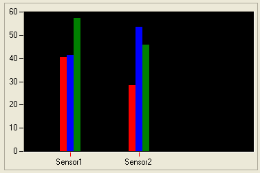
(Photo 2)
Code for (2)
using System;
using System.Drawing;
using System.Windows.Forms;
using NationalInstruments.UI;
using NationalInstruments.UI.WindowsForms;
namespace WindowsFormsApplication1
{
partial class StackedBarChartInScatterGraphExample: form
{
sets the thickness of the column.
private static int columnSize = 10;
private static color colorA1 = Color.Red;
private static color colorA2 = Color.Blue;
private static color colorA3 = Color.Green;
private static penA1 pen = new Pen (colorA1, columnSize);
private static penA2 pen = new Pen (colorA2, columnSize);
private static penA3 pen = new Pen (colorA3, columnSize);
public StackedBarChartInScatterGraphExample()
{
InitializeComponent();
}
private void timer1_Tick (object sender, EventArgs e)
{
GenerateDataAndPlot1();
}
Private Sub GenerateDataAndPlot1()
{
Read data from sensor1.
Double dataA1 = GetDataFromSensor();
Double dataA2 = GetDataFromSensor();
Double dataA3 = GetDataFromSensor();
Describe X posts. All X values must be same because we want that they in a column.
Double [] sensor1XData = new double [4] {2, 2, 2, 2 ;}
Double [] sensor1YData = new double [4] {0, dataA1, dataA2, dataA3};
scatterGraph2.Plots [0]. PlotXY (sensor1XData, sensor1YData);
Read data from sensor1.
dataA1 = GetDataFromSensor();
dataA2 = GetDataFromSensor();
dataA3 = GetDataFromSensor();
Describe X posts. All X values must be same because we want that they in a column.
Double [] sensor2XData = new double [4] {5, 5, 5, 5};
Double [] sensor2YData = new double [4] {0, dataA1, dataA2, dataA3};
scatterGraph1.Plots [1]. PlotXY (sensor2XData, sensor2YData);
}
Random r = new Random();
Private double GetDataFromSensor()
{
This is the place where you read the data from the sensor.
return r.NextDouble () * 50 + 25;
}
private void scatterGraph1_BeforeDrawPlot (object sender, BeforeDrawXYPlotEventArgs e)
{
Graph = sender ScatterGraph ScatterGraph.
If (chart! = null)
{
Graphics g = e.Graphics;
Map data points to episodes of the trace of the graph area.
Here we have the real coordinates x and y of the points.
PointF [] points = e.Plot.MapDataPoints (graph. PlotAreaBounds);
If (points. Length is 4)
{
HERE, WE DRAW THE PLOT OURSELVES.
Here we only modify the coordinates of X to meet our needs.
base point to define the base line.
value points define the upper end of the lines.
Move the point a1 by columnSize left (i.e. - ve 20 pixels)
PointF points [0] = basePoint1;
basePoint1.X = columnSize;
PointF valuePoint1 = points [1];
valuePoint1.X = columnSize;
Do not change for the middle column.
PointF points [0] = basePoint2;
PointF valuePoint2 = points [2];
Move the point a1 by columnSize right (i.e. + ve 20 pixels)
PointF points [0] = basePoint3;
basePoint3.X += columnSize;
PointF points [3] = valuePoint3;
valuePoint3.X += columnSize;
Draw lines
g.DrawLine (penA1, basePoint1, valuePoint1);
g.DrawLine (penA2, basePoint2, valuePoint2);
g.DrawLine (penA3, basePoint3, valuePoint3);
}
}
CANCEL the DRAWING TRACE of the GRAPH SINCE WE TIRONS ourselves the PLOT.
e.Cancel = true;
}
}
}
I hope this helps. If this isn't what you mean, answer me.
See you soon,.
Tags: NI Software
Similar Questions
-
How to add annotations to scattergraph?
It seems to be simple
 (on it), but I spent 2 hours by train to add an annotation to a scattergraph.
It works perfectly in design mode, but I want to do by code, something like this:
Ann As New XYAnnotationCollection Dim
ScatterGraph1.Annotations.Add (ann)
But this does not work, ann is a XYAnnotationCollection not a XYAnnotation. And when I declare it as XYAnnotation, it will not work too, (mustinherit class)!
Using VB 2005
Thank you in advance.
Thanks for the tip. Really useful.
If it can help someone else, I got it working by using a clone of the first annotation - which was made by the design and invisible.
Dim ann As XYPointAnnotation For i = 0 To Nmax
Ann = frmsuivi_tendance. XyPointAnnotation1.Clone)
Ann. Visible = True
Next I
-
Scattergraph MoveCursor method does not behave as expected
I'm trying to do something very simple: essentially keep the cursor on the last point being traced all trying to trace several scatterplots. Here is a snippet of code where I put the cursor properties:
********************************************************************************************************************************************************************************
internal NationalInstruments.UI.WindowsForms.ScatterGraph sgImpedance;
private list
m_ZDataPlots = new list () ; //clsZofFDataType is a class that represents the data in a conspiracy. ... / / more code follows here
...
sgImpedance.Cursors [0]. Plot = sgImpedance.Plots [m_ZDataPlots.Count - 1]; sgImpedance is a scattergraph initialized as above
sgImpedance.Cursors [0]. Color = newColor;
sgImpedance.Cursors [0]. SnapMode = CursorSnapMode.NearestPoint;If (sgImpedance.Plots [m_ZDataPlots.Count - 1].) HistoryCount > 1)
sgImpedance.Cursors [0]. MoveCursor (sgImpedance.Plots [m_ZDataPlots.Count - 1].) HistoryCount - 1);
on the other
sgImpedance.Cursors [0]. MoveCursor (0);********************************************************************************************************************************************************************************
The cursor keeps however remain at the centre of the plot; It is on the correct path but it is never the last traces. Is there any attribute I need to, or an event that should be raised so that the cursor to stay on the current point being traced? I have attached a screenshot to show what is happening.
Any help will be appreciated. If I need to elaborate further, please let me know. Thank you very much!
Can you provide an example of a code so I can reproduce the behavior on my end?
-
Scattergraph crash when refreshing scale the y-axis beyond a certain range programmatically
I have a subscription issue that I'm glued involving control scattergraph. I put my scattergraph to a fixed scale of 0-25 in the loading screen. When the graph is updated I check to see if the value of y is greater than the scale of the axis y. If and when it does update the scale fixed to range from 0 the previous litter, 25. So if it exceeded range 0-25, he was jumping at 0-50, if it exceeded 0-50, he was jumping to 0-75. The issue I'm having is well after the range 0-75 when he tries to change the scale of 0 to 100, the graph crashes and turns into a red x. I have no idea why it is doing at this point, so any help is appreciated. Here is my code to update the graph:
yAxisMax = YAxis1.Range.Maximum

        If val1 > yAxisMax or val2 > yAxisMax then

            ScatterGraph1.YAxes (0). Range = New NationalInstruments.UI.Range(0, yAxisMax + 25)

            ScatterGraph1.YAxes (0). MajorDivisions.Interval += 5

            ScatterGraph1.Refresh)

        End If
Don't know if it's important but I'm updating simultaneously two clouds of points.
Hello
I made a simple app with a scattergraph and a button on a form. It works very well. There must be something wrong with your values of Y.
Public Class Form1
As Double Dim yVal
Private Sub Button1_Click(ByVal sender As System.Object, ByVal e As System.EventArgs) Handles Button1.Click
Dim nowValue As Date
Dim convertedValue As Double = 0Try
nowValue = Now()convertedValue = CDbl (DataConverter.Convert (nowValue, GetType (Double)))
yVal = yVal + 5ScatterPlot1.PlotXYAppend (convertedValue, Convert.ToDouble (yVal))
Catch ex As Exception
End Try
End Sub
Private Sub Form1_Load(ByVal sender As System.Object, ByVal e As System.EventArgs) Handles MyBase.Load
TryMe.XAxis1.MajorDivisions.LabelFormat = New NationalInstruments.UI.FormatString (NationalInstruments.UI.FormatStringMode.DateTime, "h:mm:ss tt")
Catch ex As Exception
End Try
End Sub
End ClassCurt
-
points with color on a scatterGraph diffenrent
Hi all
I want to score points with diffenrent color on a scatterGraph. The color of the point must be made based on the values of a combination of the primary color (red, green, blue). Perhabs I should use the 'Color.FromArgb (red, green, blue)' method to change the color. but I used the "scatterPlot.PointColor = Color.FromArgb (red, green, blue)" to change the color of the entire points on the ground. The number of points I have is more than 80,000. You have ideas better?
Respect of
Michael
Hello
You can customize the way points are drawn in the graphic Studio measure controls. See the example in chart that comes with Measurement Studio (... \Graph\CustomStyles\...).
You can customize this way...
1. write your own CustomStyle deriving from the PointStyle class.
2. override the Draw() method.
3 override the IsValueDependent property and return true.Here is the code snippet sample showing the same thing,
Use an instance of these classes of style for scatterGraph.PlotStyle.
Point color is based on the data.
public class MyCustomStyle1: PointStyle
{
Dispersion of the cloud of points;
public MyCustomStyle1 (ScatterPlot myPlot)
{
Point cloud = myPlot;
}Public Overrides Sub Draw (context of the object, PointStyleDrawArgs args)
{
Graphics g is args. Graphics card;
Double x = 0;
Double y = 0;Rectangle rect = new Rectangle ((int) args.) Graphics.ClipBounds.X, (int) args. Graphics.ClipBounds.Y, (int) args. Graphics.ClipBounds.Width, (int) args. Graphics.ClipBounds.Height);
You can get the data points x and y by the reverse mapping.
scatterPlot.InverseMapDataPoint (rect, new PointF ((float) args.)) X, (float) args. Y), x, y);Color c = Color.White; Replace the code here to map the value of your data with a color value.
g.FillRectangle (new SolidBrush (c), new Rectangle (0, 0, 100, 100));
}public override bool IsValueDependent
{
get {return true ;}
}
}Point color is not dependent on the data
public class MyCustomStyle2: PointStyle
{
private Random r = new Random();Public Overrides Sub Draw (context of the object, PointStyleDrawArgs args)
{
Graphics g is args. Graphics card;
Color c = Color.FromArgb (r.Next (% 255), r.Next (% 255), r.Next (% 255));
g.FillRectangle (new SolidBrush (c), new Rectangle (0, 0, 100, 100));
}public override bool IsValueDependent
{
get {return true ;}
}
}I hope this helps.
-
ScatterGraph does not manually change the axis to execution interval
I use the ScatterGraph and the WaveFormGraph in VS2010 Winforms application. I have the interaction mode axes set to EditRange. The WaveFormGraph command allows to edit the axis range by clicking on the end of the axis labels and modify them. ScatterGraph control is not even though the documentation I've read says it should. The mode of the axis does not seem be the question that I have changed between fixed and AutoScaleLoose (which is not the choice to have everything showing changing data, if you want your range entered manually to maintain). I tried a new project with a ScatterGraph control with the default settings and checked that it does not change the axis interval. Is there a way to change the settings to allow you to manually edit a ScatterGraph range in this way when running?
Thank you!
Hi Lybro,
You have activated the "EditRange" of the graphical object of point clouds InteractionMode? There are two places that the mode of interaction is defined, one for the axis and the other for the scatter chart, both must be enabled for writing at work. I just tested this with Measurement Studio 2013 and it works. Let me know if it helps.
Kind regards
Kevin
-
Hi all,
I did managed to derive a CustomCursor of XYCursor at the point of being able to display an icon, or a label.
I have also managed to create a CustomGraph derived from a diagram of dispersion and to specify the color of each point of the plot in a range of colors for every points.
For my CustomCurosr, it seems very pretty because I managed to make the bottom of the color of the label semi transparent and to use small fonts. I will be able to specify the labels for the points of a ScatterGraph (in the same way). Has anyone managed to do this?
Thank you
cdouillet
PS: I am happy to give my code VB for CustomCursor and CustomScatterGraph if anyone is interested.
Hey,.
Looks like you worked a lot with the MStudio controls. Nice!
I wrote a code and rendered graphic to display labels. Here's the screenshot and the code snippet.
I hope this helps. If this isn't the case, could attach you a screenshot of the graph showing how the chart should look like? If possible, you could join the snippet for custom classes. These would help us better understand what you plan to do with the chart control.
In summary:
Code snippet:
Public Class MyScatterPlot    Inherits ScatterPlot    Protected Overrides Sub OnBeforeDraw(ByVal e As BeforeDrawXYPlotEventArgs)        ' Let the base type do its drawing first.        MyBase.OnBeforeDraw(e)

        ' Get the data points and mapped coordinates in pixels.        Dim points As PointF() = MapDataPoints(e.Bounds)        Dim xData As Double() = GetXData()        Dim yData As Double() = GetYData()

        ' Draw label for each data point.        For i As Integer = 0 To points.Length - 1            DrawLabel(e.Graphics, points(i), xData(i), yData(i))        Next    End Sub

    Private Sub DrawLabel(ByVal g As Graphics, ByVal pointF As PointF, ByVal xData As Double, ByVal yData As Double)        ' Setup the font, label and colors.        Dim label As String = xData.ToString() + ", " + yData.ToString()        Dim font As Font = New System.Drawing.Font("Verdana", 8, FontStyle.Regular)        Dim fillColor As Color = Color.FromArgb(128, Color.Gray)        Dim labelColor As Color = Color.White        Dim borderColor As Color = Color.LightGray

        ' Calculate the positions of the rectangle to be drawn.        Dim size As SizeF = g.MeasureString(label, font)        Dim r As RectangleF = RectangleF.Empty        r.Location = New PointF(pointF.X + 5, pointF.Y - 5 - font.Height)        r.Size = New SizeF(size.Width, size.Height)

        ' Do the drawing here. First draw the rectangle, fill it with some color and then draw the string.        g.FillRectangle(New SolidBrush(fillColor), r)        g.DrawRectangle(New Pen(borderColor), r.Left, r.Top, r.Width, r.Height)        g.DrawString(label, font, New SolidBrush(labelColor), r.Location)    End SubEnd Class
Habim stone,
National Instruments
-
A problem with the display in a form with a ScatterGraph
Hi all!
Now, I want to do an image that can be expanded outside and inside with the viewport in a form with a ScatterGraph window. I tried previously to do this picture as a backdrop, but the backgroundpicture cannot be zoomed with the display window. How can I solve this problem?Here is the picture:
Or I have to calculate a large amout of points to sign on the coordination of xy without the image, and how can I register quickly because it takes a long time to calculate.
Hello
You can zoom/dΘplacer an image as well as the plot in charts. Here is a snippet of code showing how you can do it.
Normal
0fake
fake
fakeEN-US
X NONE
X NONEMicrosoftInternetExplorer4
/ * Style definitions * /.
table. MsoNormalTable
{mso-style-name: "Table Normal";}
MSO-knew-rowband-size: 0;
MSO-knew-colband-size: 0;
MSO-style - noshow:yes;
MSO-style-priority: 99;
MSO-style - qformat:yes;
"mso-style-parent:" ";" "
MSO-padding-alt: 0 to 5.4pt 0 to 5.4pt;
MSO-para-margin-top: 0;
MSO-para-margin-right: 0;
MSO-para-margin-bottom: 10.0pt;
MSO-para-margin-left: 0;
line-height: 115%;
MSO-pagination: widow-orphan;
font-size: 11.0pt;
font family: 'Calibri', 'sans-serif ';
MSO-ascii-font-family: Calibri;
MSO-ascii-theme-make: minor-latin;
mso-fareast-font-family: "Times New Roman";
mso-fareast-theme-make: minor-fareast.
MSO-hansi-font-family: Calibri;
MSO-hansi-theme-make: minor-latin ;}
table. MsoTableGrid
{mso-style-name: "Table Grid";}
MSO-knew-rowband-size: 0;
MSO-knew-colband-size: 0;
MSO-style-priority: 59;
MSO-style-unhide: no;
black border: solid 1.0pt;
MSO - border - themecolor:text1;
MSO-border-alt: solid black .5pt;
MSO - border - themecolor:text1;
MSO-padding-alt: 0 to 5.4pt 0 to 5.4pt;
MSO - border - black insideh:.5pt United.
MSO-border-insideh - themecolor:text1;
MSO - border - black insidev:.5pt United.
MSO-border-information - themecolor:text1;
MSO-para-margin: 0;
MSO-para-margin-bottom: .0001pt;
MSO-pagination: widow-orphan;
font-size: 11.0pt;
font family: 'Calibri', 'sans-serif ';
MSO-ascii-font-family: Calibri;
MSO-ascii-theme-make: minor-latin;
MSO-hansi-font-family: Calibri;
MSO-hansi-theme-make: minor-latin ;}Image img =
Bitmap.FromFile ("myImage.jpg");in pixels, this is the place
where the image will be drawnRectangleF initialRectangle = Rectangle.Empty;
in the data, to map coordinates the
imageXRange range;
Range yRange;
Private Sub PlotMyData()
{
plot your data here
xData double [] = new double [] {3, 5, 7, 5, 8, 3, 7, 8, 2, 6};
Double]
yData = new double [] {9, 1, 2, 6, 8, 3, 3, 6, 2, 2};scatterGraph1.PlotXY (xData, yData);
xRange and yRange define the plot area limits left-top to bottom-right
xRange = new range (xAxis1.Range.Minimum, xAxis1.Range.Maximum);
yRange =
new range (yAxis1.Range.Minimum, yAxis1.Range.Maximum);RecalculateImageBounds();
}
Simply map the data coordinates
values in pixelsposts from the top left and lower right must be mapped.
Private Sub RecalculateImageBounds()
{
PointF
size = scatterPlot1.MapDataPoint (scatterGraph1.PlotAreaBounds,
(xRange.Maximum, yRange.Minimum);initialRectangle.Location =
scatterPlot1.MapDataPoint (scatterGraph1.PlotAreaBounds, xRange.Minimum,
yRange.Maximum);initialRectangle.Width = size. X - initialRectangle.Location.X;
initialRectangle.Height = size. Y - initialRectangle.Location.Y;
}
Just draw the image.
Private Sub scatterGraph1_BeforeDrawPlot (sender As object, BeforeDrawXYPlotEventArgs
(e){
RecalculateImageBounds();
e.Graphics.DrawImage (img, initialRectangle.X, initialRectangle.Y,
(initialRectangle.Width, initialRectangle.Height);}
Make sure that the image is of good quality so that you can zoom in pretty close.
I hope this helps.
-
How can I change the color of the plots (lines, points) in the collection Scattergraph plot
For example, I go through a foreach loop and draw two points. How to distinguish this set of plots of the yet to come? How can I change the style, color and have separate lines (instead of on the line connecting everything) for each of my plots? I don't know how to set everything up, but it still does what he wants to do. TIA.
Hello
The problem you see occurs because of the following lines of code:
The _data and _data2 scatterPlot3 value
_data = scatterPlot3
_data2 = scatterPlot3
When you do this, you define _data as _data2 to reference an object of the simple concession - scatterPlot3. Yes, even if you have (from the code you have posted at least) three slots in your collection, they are all pointing to the same object of point cloud. So when you change the color for one, it changes the color for them all. However, I think that you have fallen on the right solution in your last sentence. If you want to have multiple locations on your ScatterGraph, each with its own color and style, they should each be separate and unique plots in the collection plot of your ScatterGraph. Based on the code you posted, you'll see this if you comment just the two lines shown above.
Please let me know if something is still uncertain.
NickB
National Instruments
-
Scattergraph annotation shape size
How can I set the Shape.Size Annotation of the ScatterGraph with a scale of XAxis.
Exsample: if I have the XAxis with a scal YAxis with scale 0-10 and 0-1000 and I want the form to 0-500 I can not put the Shape.Size (500,10)?
TNK
Okay, I use ScatterGraph.XYRangeAnnotations instead of XYPoinAnnotations.
Problem solved
-
Tick-BarChart axis labels are missing in JDK1.8
Hi guys!
Currently, I'm trying to integrate a JavaFX BarChart in my existing Java application. So I need a my BarChart BufferedImage, so that I can make this snapshot on a graphics instance.
I adapted the existing BarChartSample.java (Graphic sample |) Tutorials of JavaFX and Documentation) and deleted all the animations. The hand of code works fine but I have identified a problem-> my TickLabels lack
The TickLabels are visible if I use JDK 1.7u51 but if I change the JDK 1.8u05... the stlye of my histogram will be changed and my tick labels are not visible.
I missed something or is this a bug?
Thanks in advance!
Best regards
Steve
----------
using the JDK 1.7u51
https://drive.Google.com/file/d/0B7P_rknS1TWxMUVaRHNzNzBEWVk/edit?USP=sharing
using the JDK 1.8u05
https://drive.Google.com/file/d/0B7P_rknS1TWxZFV6ZVZvR3ZqM3M/edit?USP=sharing
My adapted code is as follows:
package barchartsample;


import java.awt.Graphics;
import java.awt.image.BufferedImage;
import java.util.concurrent.Callable;
import java.util.concurrent.ExecutionException;
import java.util.concurrent.FutureTask;


import javafx.application.Platform;
import javafx.embed.swing.JFXPanel;
import javafx.embed.swing.SwingFXUtils;
import javafx.scene.Scene;
import javafx.scene.chart.BarChart;
import javafx.scene.chart.CategoryAxis;
import javafx.scene.chart.NumberAxis;
import javafx.scene.chart.XYChart;
import javafx.scene.image.WritableImage;


import javax.swing.JFrame;
import javax.swing.JPanel;


public class BarChartSample
{
  /**
  * Initialize JavaFX
  */
  private static final JFXPanel initializeJFX = new JFXPanel();

  final static String austria = "Austria";

  final static String brazil = "Brazil";

  final static String france = "France";

  final static String italy = "Italy";

  final static String usa = "USA";

  public static void main(String[] args) throws InterruptedException, ExecutionException
  {
      JFrame frame = new JFrame();
      frame.setSize(815, 640);

      frame.add(new JPanel()
      {

            @Override
            public void paint(Graphics g)
            {
                try
                {
                      g.drawImage(getChartImage(), 0, 0, null);
                }
                catch (Throwable t)
                {
                      t.printStackTrace();
                }
            }
      });
      frame.setVisible(true);
  }

  static BufferedImage getChartImage() throws InterruptedException, ExecutionException
  {
      FutureTask<BufferedImage> future = new FutureTask<BufferedImage>(new Callable<BufferedImage>()
      {
            @Override
            public BufferedImage call() throws Exception
            {
                final CategoryAxis xAxis = new CategoryAxis();
                final NumberAxis yAxis = new NumberAxis();
                final BarChart<String, Number> bc =
                new BarChart<>(xAxis, yAxis);
                bc.setTitle("Country Summary");
                xAxis.setLabel("Country");
                yAxis.setLabel("Value");

                XYChart.Series series1 = new XYChart.Series();
                series1.setName("2003");
                series1.getData().add(new XYChart.Data(austria, 25601.34));
                series1.getData().add(new XYChart.Data(brazil, 20148.82));
                series1.getData().add(new XYChart.Data(france, 10000));
                series1.getData().add(new XYChart.Data(italy, 35407.15));
                series1.getData().add(new XYChart.Data(usa, 12000));

                XYChart.Series series2 = new XYChart.Series();
                series2.setName("2004");
                series2.getData().add(new XYChart.Data(austria, 57401.85));
                series2.getData().add(new XYChart.Data(brazil, 41941.19));
                series2.getData().add(new XYChart.Data(france, 45263.37));
                series2.getData().add(new XYChart.Data(italy, 117320.16));
                series2.getData().add(new XYChart.Data(usa, 14845.27));

                XYChart.Series series3 = new XYChart.Series();
                series3.setName("2005");
                series3.getData().add(new XYChart.Data(austria, 45000.65));
                series3.getData().add(new XYChart.Data(brazil, 44835.76));
                series3.getData().add(new XYChart.Data(france, 18722.18));
                series3.getData().add(new XYChart.Data(italy, 17557.31));
                series3.getData().add(new XYChart.Data(usa, 92633.68));

                bc.getData().addAll(series1, series2, series3);
                Scene scene = new Scene(bc, 800, 600);

                WritableImage fximage = scene.snapshot(null);

                return SwingFXUtils.fromFXImage(fximage, new BufferedImage((int) Math.ceil(fximage.getWidth()), (int) Math.ceil(fximage.getHeight()),  BufferedImage.TYPE_INT_ARGB_PRE));
            }
      });

      Platform.runLater(future);
      return future.get();
  }
}
Feedback from a developer:
This is because the labels are busy (melted), so they are not visible on the first image (that you captured). You must set
xAxis.setAnimated (false);
yAxis.setAnimated (false);-> This works for me ;-)
-
Get rid of BarChart legend and create a horizontal line to a specific value
Hey,.
I work with barregraphes.
1st screen: I want to disable the legend of my Barchart.
http://imgur.com/wMo6Tfv, DRiNA9C
Second screen: I want to create a line in my Barchart on a specific value 700 as seen on the screen.
http://imgur.com/wMo6Tfv, DRiNA9C #1
Is this Possible? Also: what object to set the ID to change the color bar. I tried
Chart histogram;
barchart.setId ("Chart");
CSS:
#barchart
{
-fx-background-color: red;
}
But it did not work. Thank you!No, you do not miss anything. I had a temporary brain freeze. You can add nodes directly to an arbitrary region.
If this makes it a little harder. You need to add the line to the container in which your chart is maintained, and of course this means that you understand the coordinates of the line relative to this container. To simplify a bit, axis has a scale property of conversion of units of the axis to display units, and also according to the docs of css, the table has a child with the css class "table-horizontal-zero line." So one possible strategy is to enter this line and figure the change in the coordinates needed him. There is still work to do to find the correct coordinates relative to the container, and if you want it to run with things move (for example, when the user resizes the window), you need to do a lot of link.
This seems to work:
import java.util.Arrays; import java.util.List; import javafx.application.Application; import javafx.beans.binding.DoubleBinding; import javafx.beans.property.DoubleProperty; import javafx.beans.property.SimpleDoubleProperty; import javafx.event.ActionEvent; import javafx.event.EventHandler; import javafx.scene.Node; import javafx.scene.Scene; import javafx.scene.chart.CategoryAxis; import javafx.scene.chart.LineChart; import javafx.scene.chart.NumberAxis; import javafx.scene.chart.XYChart; import javafx.scene.control.Button; import javafx.scene.layout.AnchorPane; import javafx.scene.layout.BorderPane; import javafx.scene.layout.Region; import javafx.scene.shape.Line; import javafx.stage.Stage; import javafx.util.StringConverter; public class LineChartSample extends Application { @Override public void start(Stage stage) { stage.setTitle("Line Chart Sample"); final CategoryAxis xAxis = new CategoryAxis(); final NumberAxis yAxis = new NumberAxis(); yAxis.setTickLabelFormatter(new StringConverter() { @Override public Number fromString(String string) { return Double.parseDouble(string); } @Override public String toString(Number value) { return String.format("%2.2f", value); } }); xAxis.setLabel("Month"); final LineChart () { @Override public void handle(ActionEvent event) { final double lineLevel = 35; final Region chartRegion = (Region) lineChart .lookup(".chart-plot-background"); final Line zeroLine = (Line) lineChart .lookup(".chart-horizontal-zero-line"); final DoubleProperty startX = new SimpleDoubleProperty(0); final DoubleProperty endX = new SimpleDoubleProperty(0); final DoubleProperty y = new SimpleDoubleProperty(0); startX.bind(new DoubleBinding() { { super.bind(chartRegion.boundsInParentProperty()); } @Override protected double computeValue() { double x = chartRegion.getBoundsInParent().getMinX(); for (Node n = zeroLine.getParent().getParent(); n != chartContainer && n.getParent() != null; n = n.getParent()) { x += n.getBoundsInParent().getMinX(); } return x; } }); endX.bind(new DoubleBinding() { { super.bind(chartRegion.boundsInParentProperty()); } @Override protected double computeValue() { double x = chartRegion.getBoundsInParent().getMaxX(); for (Node n = zeroLine.getParent().getParent(); n != chartContainer && n.getParent() != null; n = n.getParent()) { x += n.getBoundsInParent().getMinX(); } return x; } }); y.bind(new DoubleBinding() { { super.bind(chartRegion.boundsInParentProperty(), yAxis.scaleProperty(), zeroLine.startYProperty()); } @Override protected double computeValue() { double y = zeroLine.getStartY() + lineLevel * yAxis.getScale(); for (Node n = zeroLine.getParent().getParent(); n != chartContainer && n.getParent() != null; n = n.getParent()) { y += n.getBoundsInParent().getMinY(); } return y; } }); Line line = new Line(); line.startXProperty().bind(startX); line.endXProperty().bind(endX); line.startYProperty().bind(y); line.endYProperty().bind(y); chartContainer.getChildren().add(line); } }); BorderPane root = new BorderPane(); root.setCenter(chartContainer); root.setTop(button); Scene scene = new Scene(root, 800, 600); lineChart.getData().add(series); stage.setScene(scene); stage.show(); } public static void main(String[] args) { launch(args); } } -
Hello.
I would like to know why, when I provide my barchart component with a data provider that a single value, the corresponding bar height is adjusted to the approximately of 1 pixel. However if I add a second value, even zero, the height again correct.
Thank you.
It's normal!
bar has width = 1, so first value is close to 0, but automatically the interval [0, 100] is displayed. (You can see in the LinearAxis source)
After setting the second value, autoamtically recalculated max. So, you see the second photo.
You can set manually maximum.
-
Adding lines to the ToolTip on a BarChart
I have the histogram in my application
< mx:BarChart = "35" x = "{this.height * 0.025}" id = "EmpUtil" height = "{euSize}" width = "90%" dataProvider = "{euDs}" showDataTips = "True" themeColor = paddingLeft = "5" paddingRight = "5" ' #E3F1CE">"
< mx:verticalAxis >
< mx:CategoryAxis categoryField="@name"/ >
< / mx:verticalAxis >
< mx:series >
"< displayName ="Employee"xField="@percent mx:BarSeries "fill = race"{sc2}"="{s4}"/ >
< / mx:series >
< / mx:BarChart >
When I mouseover an element, I get a tool tip that displays the text "used", as well as the data of the area name (@name) and the value of the xField (@percent)
How can I add a third field to my ToolTip display that is not part of the axis desabscisses or XField? I tried the definition of a field and put the text 'Employee' in there in place, but I cannot understand the syntax to get my data in this field. I tried to do a function, a variable etc. combining a new field @code, the @percentage, and my name, but I can't get anything to work or even to spend checker. Can anyone help with this?
M.Then, something like this might work:
public void dtFunc(hd:HitData):String {}
Return hd.item.name + "" + hd.item.code + "" + hd.item.percent + "%";
}
]]>
dataProvider = "{euDs.worker}" "
showDataTips = "true".
dataTipFunction = "dtFunc."
>
<>
yField = 'to 100'
xField = "name".
/>
You use the item property to refer to individual items in the HitData object.
HTH,
Matt Horn
Flex docs -
How to plot the graph control scattergraph mulitple?
Hello
I have two double arrays declared and I'd draw x and y and x x. I can do one at a time, how can I add so that x, y and x, x points are displayed. I tried to use the plotXYmulitple command, but it requires a 2D array. What I need to convert my 2D table data or there is an easier option? any help would be greatly appreciated.
You are absolutely right! That's what happens you encode two o'clock in the morning. I'm writing my own solution below in the case where any other interested person. But you know it will be nice if you can make mulitple conspire like matlab function plot(x,y,x,y) etc.
Thanks again!
Kashif
            double[] xValues = new double[5] { 1, 2, 3, 4, 5 };            double[] y1Values = new double[5] { 1, 2, 3, 4, 5 };            double[] y2Values = new double[5] { 1, 4, 9, 16, 25 };

            scatterGraph1.DefaultDataOrientation = DataOrientation.DataInColumns;

            double[,] yValues = new double[xValues.Length, 2];

            for (int i = 0; i < xValues.Length; i++)            {                yValues[i, 0] = y1Values[i];                yValues[i, 1] = y2Values[i];            }

            scatterGraph1.PlotXYMultiple(xValues,yValues);

Maybe you are looking for
-
Countdown to 3500 sec asking the password
I took my yoga 13 to have the lower lid, replaced at a computer store, because it was cracked. When I came back the system was on a countdown of the second 3500 and request password. I've never been a up I tried the autour call and taking for geek te
-
Salvation OR engineers, How can I deploy the WSN library in an executable file? Thanks in advance, Luiz
-
Photo scan of computer image file
HP Photosmart C5280 All in one, when scanning photo in photo computer file all I get is the screen scanning with the little picture in the upper corner. I am uable to change or expand before or after scanning. I've recently updated to windows 7 fro
-
Keep the NumLock on after startup
How to start windows with the number lock?
-
Computer does not work - task scheduler, free 32 bit problems Analyzer engine
Hi guys,. I've seen this problem in several forums, but I think that my problem is slightly different. I turn on my computer, after which I get loads of different signs in this order: Task Scheduler engine has stopped working debugger analysis free 3