Blockdiagram of a PID controller
In order to work properly for the below the NEST attached diagram frontpanel controller which will be the blockdiagram? Help PLz.
If you double-click on the block of transfer function, you can select "Terminal" or "Configuration". If you use a Configuration, it will allow you to enter the information directly in the block with the creation of an external model.
I highly recommend also to see these resources below:
http://multimechatronics.com/images/uploads/tutorial/LabVIEW%20SimulationTutorial.PDF
http://zone.NI.com/DevZone/CDA/tut/p/ID/5855
I hope this helps.
Tags: NI Software
Similar Questions
-
PID controller compatible LabView
Hi all
We have built an oven of automated test. It was decided that it is cheaper and more convenient to use a pre built the PID controller, however
our task is to set the temperature of the oven by using LabView code, so the PID should communicate with the computer.
I would be really grateful if you could give me a little advice if these controllers exist and where they are or it could be easier to use the box of DAQ + OR PID
box tools + with external power supply + heating element power transistor.
PS just to note, temperature range is not very high (20-200 ° C)
All the best
Alexander
Hi Alexander,.
When you talk about PID controller, there are two options:
1 software based controller PID (you can develop using the LabVIEW PID toolkit)
2. regulator based material PID... If you choose to have a PID of hardware in service, you must ensure that it can be used with LabVIEW, I know that what is your concern...!
For most of these PID regulators (hardware) are an instrument of series (RS-232, RS-485 or MODBUS based) and which can be easily integrated with LabVIEW... no tool is necessary, but all you need is VISA functions or MODBUS library.
-
without using DAQ how a PID controller for temperature control
Mr President.
IAM trying to make a PID controller for temperature control in labview. But I have no devices data acquisition. Then without using DAQ how a PID controller.please suggest some useful block diagram.plz give me an answer. I tried one, but not working.below attached is my work.
as a learning exercise, some devices can be simulated in the Explorer to measure (performance measure explore, right click on devices, select Create new.) Select simulated device and choose your device, you can search by product code for example 4070 for a dmm)
I hope this helps you begin to learn labview, depending on how advanced you can I strongly suggest looking in training of core 2 and core 1 but also by looking at the examples that come with labview
-
Excel sheet entry to 'setpoint' of the PID controller
Hello
I use this (attached) vi to control the thermostat of Lakeshore. I got the website vi OR. I want to change the vi as to the set value, it takes as input an excel sheet (could be any other form too). This spreadsheet contains a list of temperatures. The vi reads the first temperature and then that sets the value of the PID controller setpoint. Once the set point is 'set' the vi waiting for awhile (say 1 hour) before reading the next entry in the excel sheet set point. I want to wait that it is because I programmed a gamma spectrum software such that it counts for 1 hour and then starts a new count. The part of the spectrum is not very intelligent but its ok for now. The problem I have is that when I run this vi (attached), the indication of the set on the temperature controller (hardware) tends to zero and stays there. Can someone help me by pointing out the error that I do. This vi is Labview based 6.0 (it's a bad implementation!)
Thank you
Saurabh
Slim,
You could possibly have the calendar in step in the worksheet as well?
It would be a classic case where you could use state machines (or producer / consumer - events if the user input is critical), research of this architecture and examples on ni.com. Also for synchronization purposes, are looking for functional global timer or try to modify this example https://decibel.ni.com/content/docs/DOC-6523 to add 'elapsed time' (as in the elapsed time express vi) features similar to this code.
You have reports such as:
Initialization: initialize your control panel front/graphics etc. Read the spreadsheet file. Make sure that the comms exist between the software and the controller, etc..
Set the temperature: set the first value, start a countdown (depending on what you set)
State check: check the status of controller etc failure. Check if the user has pressed the stop button. Check if the timer in the previous state has expired?
In case of error stop the timer and take the measures necessary to correct, to report to the user
If the user has pressed the stop button, close all references, etc hard reset and exit the application.
If the timer has expired, get the next value and go on to set the temperature.
I hope this helps.
-
value of PV in the PID controller may be a string?
Hi all
I'm trying to generate a humidity control using the mass flow controller. I have a USB moisture sensor. The reading of the probe are sent in a spreadsheet and converted string. The value (a string) is used to enter the value of the pv of the MIP? Is it achievable?
Thank you!
Just use one of the chain of digital features.
-
-
Basic concept of loop PID closed
Hello
I have a problem of very basic concept of PID loop closed. I read a lot of material of the PID controller but still confused.
I understand that the error between the measure and the desired will be processed by PID controller, but I do not understand how the controller output (sum of three P/I/D) set the right plant behand the controller. For example, an electric motor fan will be below on a Board, the force of the wind on the motherboard could be detected by the tension and of course the fan speed could be adjusted by tension. But the error of the setpoint and the process variable will go directly to the fan in Labview without identifying the mechanisms on the plant (fan). I wonder if anyone knows how this error is treated by the plant. And why we need not care about the transfer of the factory function.
If you have a transfer function for your plants, you don't need PID, because the output of the optimal control can be determined directly from the transfer function! (Well, more specifically, often in this case you would use the transfer to feed-forward control function, which you would combine with PID to correct minor variations between the reality and transfer function model.)
The output of PID is not a sum of errors. It is a sum of the outputs of regulation - the proportional output, the full output and the derived products output. The gains set the regulator to the specific system, and if they are not chosen correctly, the control will be terrible and potentially unstable.
In your hypothetical example of two systems - Yes, it is quite possible that one moment the error and so the output will be the same. But if the systems are very different, the next iteration of control errors will be different, so the next controller output value will be different, etc. And if the systems are very different, they should not have the same gains.
-
Hello world.
I wrote a program of temperature control in labview and used the PID Toolkit for it.
The entrance to the PID is the measured temperature and the output is a PWM signal fed to a relay that turns heater on or off.
The control works but I want the temperature to be stable within a range of + - 2%.
Currently, the temperature varies more than that.
IAM sure, this is the setting of the PID.
Because I have not worked with regulators PID Iam not exactly how to tune my system.
The best way I found is to zero I and D and make the system oscillate with P.
The only problem is that the system of temperature is so slow that it takes quite a long time to reach the set point which in turn would mean a lot of hours of tests only.
Now Iam just wondering if there is a faster way to set the PID controller?
Thanks in advance,
Best regards
Michael
I've used this method several times with slow heating appliances. It can take a long time to reach a stable temperature, but at least do not monitor constantly as he approaches this value.
In figure 3.4, Yes, the Min value is the initial value that is stable. It is OK to start an initial PWM output of 0, which speeds up the process, if your radiator is already at a steady temperature (the temperature in the room).
In general, the difference between the output of the first and the last values, better will be your control (you will get best results of going from 0 to more than 50% to 5%), but it will take more time to settle to a new value and of course you must ensure that you do not exceed the capabilities of your system. It's a good idea to have a separate alarm system in place that can cut power to heater if you exceed a temperature, especially if you plan to walk away from it until it stabilizes.
To a fixed cycle, the system will not continue to heat up indefinitely unless you have a perfect insulation without heat loss - but, as I mentioned above, do not choose a value that will not cause the system to overheat.
-
State Machine with PID control
Hi, I currently have a problem with my state machine, I control two cylinders double effect in sequence that works very well. However, there is one point I need to increase the pressure in the cylinder and to maintain this pressure through the sequence of State machine, however when the state machine transitions to the next indicate the PID controller resets, how can I solve this problem? Everything in is also allowed to apply the pressure in the cylinder another (same node IO accessed).
Thank you I joined my project in a WinZip file, then it will have to be extracted. The two main VI to watch is 'Park Brake FPGA VI New' and 'park brake host VI update 2 "(new)
Thank you.
Nevermind I solved the problem with a parallel loop.
-
Synchronization of multiple FPGA PID loops
Hello
I am the design of a PID controller for each of the three axes (X, Y and Z) of a piezoelectric stage using the FPGA module and a cRIO. I used the example of project "Using Discrete PID - cRIO.lvproj" (labview\examples\control\pid\fpga.llb\CompactRIO) as a starting point and I've basically added two PID loops more on the FPGA VIs to the other two axes. I can get the controller to work for an axis at the same time (in simulation mode), but whenever I try to run all three controllers simultaneously, only one works. In order to synchronize between the host and the FPGA VIs, I used three interruptions for each PID loops, but it seems that a single interruption works when I run the code... No idea how to synchronize the three loops of PID with the host VI?
Kind regards
Shin
I think that it is an expected behavior, by the documentation: "VI the interruption is a shared resource, so multiple uses of it induce a further delay and jitter due to arbitration." If you are waiting for the interruption to see, then the other loops cannot continue because interruption VI does not work. On the FPGA if you want all the PIDs to operate at the same speed of loop, put them all in the same loop and use only a single interruption. Or use another synchronization mechanism (set to a boolean of the host, wait it is defined and then erase it on the FPGA). The interruption is only for purposes of simulation, in any case, since the 'central' is running on the host computer. In a real system, the plant works continuously and FPGA directly reads the sensors and outputs, the readers so the only value provided by the host is the set point and is not required for synchronization.
-
PID does not return any output...
Hello everyone...
process sbRIO on board and using the audio and vibration Simulator
below I have attached my RT + FPGA... code to control the speed of the fan... using PID...
RT. front panel
set range
1000, -1000
set point... 5000 RPM (speed is the parameter)
PID GAINS...
the values calculated at the time of the executin arbitraty... KC = 1, gain full (Kc * Ts/Ti) = 0.011718,.
derivative gain (Kc * Td/Ts) = 0
other considerations
Maximum speed of the fan is 6000 RPM
tachometer on the vibration signal Simulator is 2 impulses/turns
the speed is measured accurately
Manual disturbance can be given by varying the analog output voltage
If the pid is introduced into RT it works fine...
but, when the pid (in fpga) is introduced not able to disturb and also not output to
all other parameters is reset (final rpm, out outputanalog)
all equal to zero
This data set is meaningless... I suggest that you check that you actually save the correct values, and you have the wired PID controller correctly upward.
There are times when (?) heated, but the speed does not change. Also there are times where speed (?) has a step increase, but there is no change in voltage. You can also see places where 5V is applied but different speeds are generated. Of course, it would be much clearer if you labeled your data, including units.
Open-loop can the system actually achieve 4000 rpm with the applied 5volts? Try to start with a set point which is at the centre of its work.
The ramps are integral single action? What gains have used here. You should try proportional only first of all, make sure that everything is working properly and then only start watching full action.
-
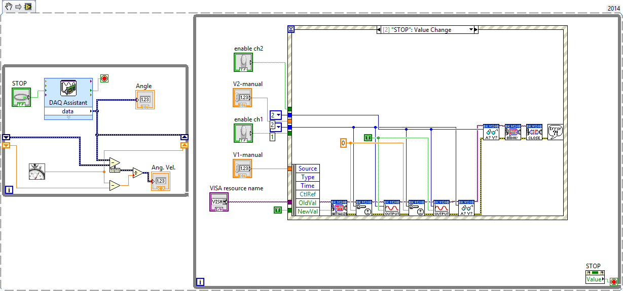
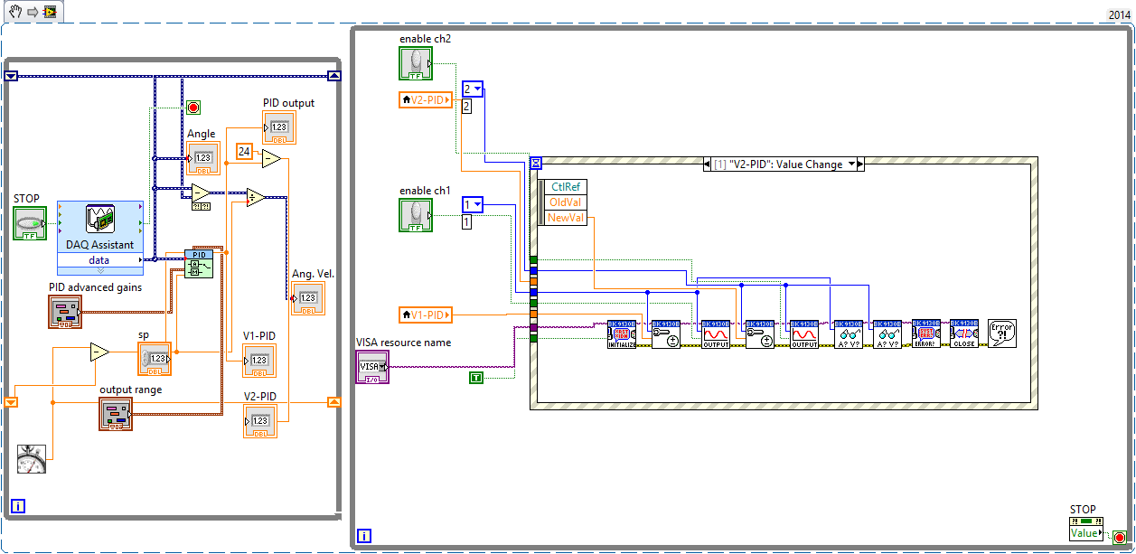
Note: I know that this post can be considered off-topic, but I think my problem is with how I'm trying to control my instrument (not the PID controller); That's why I posted my question here. Please correct me if I'm wrong.
Seen: I have a power supply programmable dual channel, a wheel and a PID controller.
Find: The encoder feedback, I would like to use the PID controller to control the outputs on my power supply.
My solution
Using the VI below, I can read the encoder and adjust the power supply without a regulator PID. The left loop reads the encoder data, and the loop on the right allows me to "manually" resolve tensions on the channel 1 and channel 2. Specifically, a structure of the event inside the loop on the right send recent tensions 'channel' (as I entered in the respective controls) power supply.My problem
However, the law while loop is not "react" when I can replace this "manual" voltage control a PID controller. The power supply simply does nothing even though the PID is indicative of the power to do something.Attempt to correct
Mode "highlight execution", I noticed my left loop would complete many iterations, but data in the loop on the right had to run only one time - and even in this case data arrested when he reached the structure of the event.Questions
- My PID control loop does not work because the PID loop (left) runs too fast compared to my power supply loop?
- What would you recommend? Filers?
- (Slightly unrelated) How should I wait the last strains of my diet?
The two blocs 'read out' in the loop of power should allow me to display the real tension of a channel. However, these data are always a 'step' behind the actual reading.
For example, I put V1 = 12V. Food reacts and displays 11.998V on its LCD screen. However, my LV code displays 0V (or any busy V1 value). If I change again V1, say V1 = 7.9V, then the power displays 7.989V but the code LV displays 11.998V. What I am doing wrong?
Writes that if I set V1 and then set V2, my LV code displays the value of the V1 correct but not the last value of V2.
Well, the first problem is obvious. You initialize the power whenever the event occurs. (DON ' T DO THAT! ")
Initiallize ONCE
Loop ON
Read the answer
Feedback monitor
Adjust the stimulation
until the output is requested
Output control loop
Close resources ONCE
-
How can I set a deadband for PID regulation
When I use a PID. VI to set pressure, when the PV nearby OAS, I want the PID.vi hold its output, but I have no idea to set the parameters of dead zone! (can not find the definition of dead zone)
An engineer PLC said that the dead zone is a common parameters PID, but idon't know not how to configure in labview pid!
Help, please, thank you!
You've already written that you have to do. A possible implementation is simply "freeze" the output of the PID controller. Use the "advanced version" of the screw of PID (normal or with automatic adjustment in case of need).
-
Regulator PID very slow to reach the value Point and zeros process Variable when it should not
Hello
I am using a PID controller to regulate the emission of a filament current in an ion gauge, but I'm running into several problems.
The first and less important, are the controller of PID VI takes at least 5 minutes to get the current where it needs to be. Is it possible to speed this up?
The second and more important, are that the PID controller tends to zero the process variable before you start the process of getting the close process of the target value variable. This can be seen in the attached VI: I write 5.8 volts voltage filament - something I did at the beginning to try to get the controller PID for the process close to the target faster - value variable but when the PID controller starts to do his thing, he kills the tension before anything, rather than rise of 5.8 V.
The attached VI is a single which has these problems. VI actual ion gauge controller I've written has the same problems, but in a form even more frustrating. I have a while loop set up for the filament voltage to where it should be (using a PID controller) first and foremost, then a loop of data acquisition, which also includes a feedback loop in the form of a PID regulator to maintain the filament voltage. When the second PID controller starts to run, it concentrates the tension that the earlier had set, taking another 5 + minutes to reach the point where we can take data and giving us 5 minutes of false data in the process!
Does anyone know why PID controllers are behaving like this, and what can I do to fix/work with this behavior?
Hello
It seems that PID VI will always be 0 for the first iteration. You can, however, use the advanced PID VI and set up the first iteration in manual mode. After subsequent iterations, you could then define this automatic mode and there will be a transition smoothly. I think this will give you the desired behavior.
-Zach
-
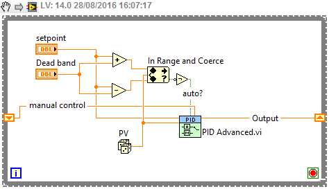
Manual of PID for transfer Auto smooth
Hello
I am using the PID command for a pump to ISCO syringe with manual Steplessly in automatic control, but I can't seem to make it work.
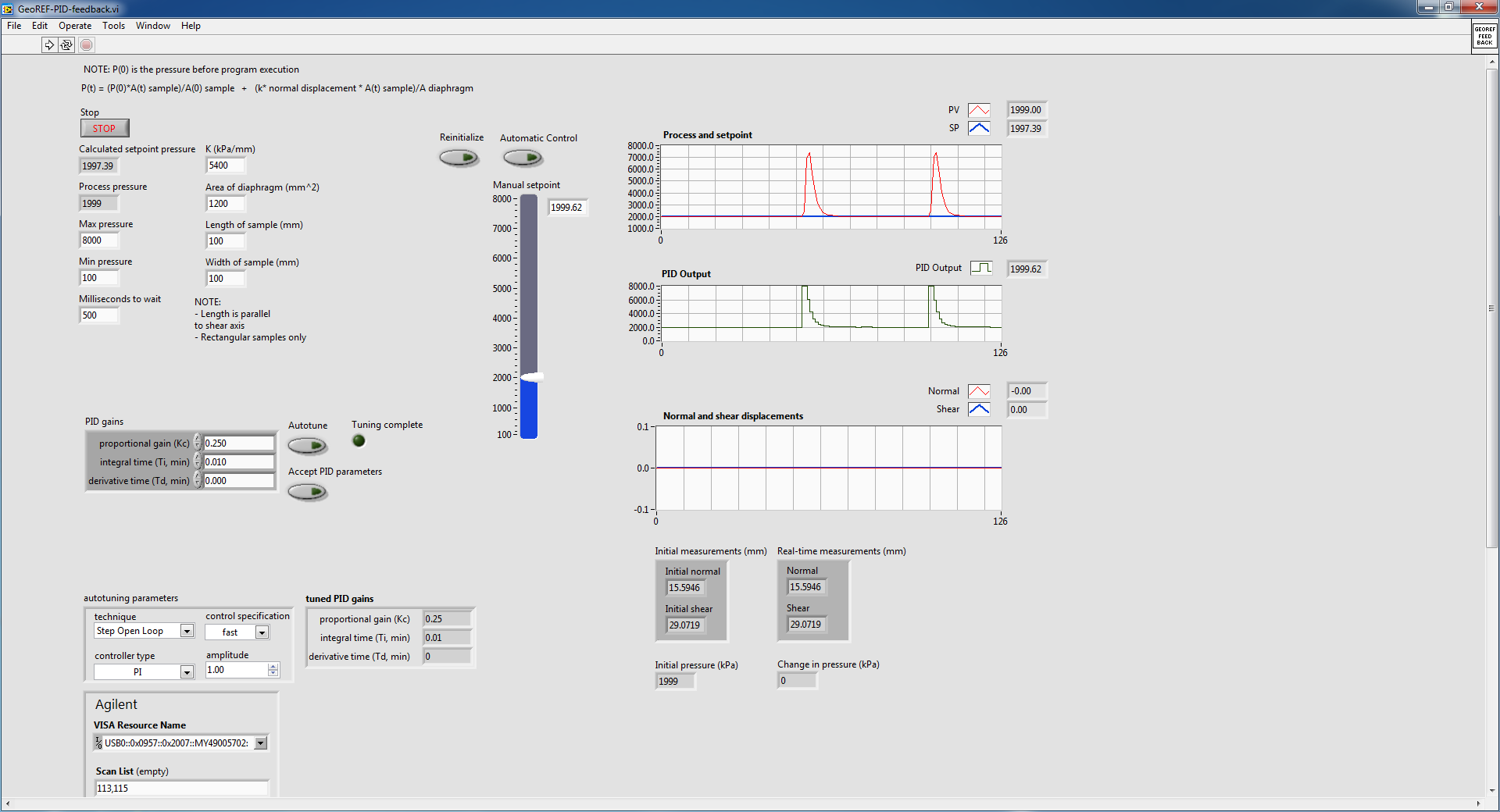
This shoot-syringe has an entry and exit pressure and is used to apply a force to keep the vertical movement of a constant of the sample. The amount of applied pressure is related to vertical displacement by an equation that appears in the attached VI. This VI aims to apply a variable force according to the displacement of the sample in order to try to keep moving 0.
Here is some general information on the pump that I use:
The pump is autonomous and can independently maintain pressure regardless of the LabVIEW PID controller. The pump only takes pressure of LabVIEW controls and maintain this pressure until another pressure control (I think that the pump integrated into the controller itself is a regulator PID.)
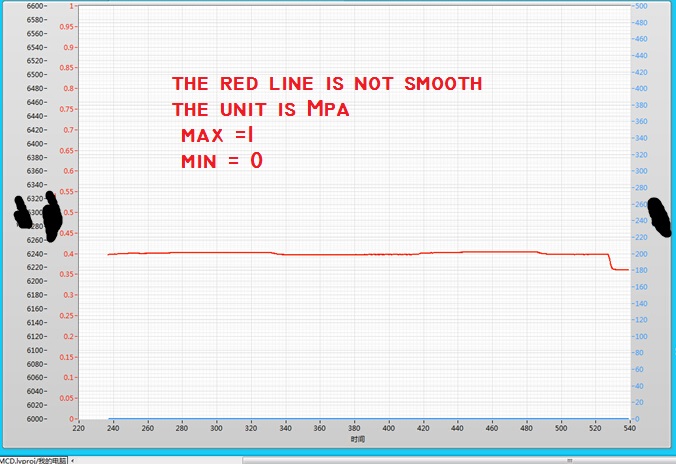
The problem I have is if I start the VI with the pump at a constant pressure (using the hand control with advanced PID VI) and crossing the wire to automatic control, the advanced PID VI immediately shows the pump to adjust the pressure up and then slowly bring it down to the steady state. This happens even if the hand control pressure is stable and identical to the auto set pressure. This following image details what I'm talking about:
The pump is in steady state, as shown in the diagram of pressure and the value in manual initially and then toggled mode on automatic control (designating the huge bump). I did it twice to show what happens when I go back. Manual automatic is without suddenly, because I used a local variable to constantly change the manual set temperature.
I did some troubleshooting and experiment and here are some of the results that I found:
1. when going from manual to automatic control, PID regulator sets the maximum pressure and then slowly bring it down to the set value
2 when it is cold from the VI in automatic mode with true to reset, the PID controller sets the pressure at a minimum and then slowly bring it up to the set value. This occurs even if the value of the original process is close to the set point (feed the actual value in the PID controller before execution also does not help.)
I also tried to play with the gains of PID in VI and found that if I turn off the 'I' and parameters "D" (together the two to 0), I no longer suffer from the huge bump, but the PID controller can bring the real set point value as there is always a lag.
I don't know if this is a result of bad PID tuning, but after the initial bump in the transition between manual and automatic, the PID controller seems to be able to maintain the correct pressure well.
The reason why I am using a PID controller rather send the pump controls (since it can independently maintain pressure) is because it is much smoother.
In the attached VI, there are a few side screws that are called that are specific to the pump and the LVDT used for detection of vertical movement. I do not think that they have an effect on why I don't get a transfer smoothly without jerking, so I only put comments to explain what they are doing.
I found another thread in forum with a similar question, but none of the solutions posted it seemed to have helped me. Here is the link to this thread:
http://forums.NI.com/T5/LabVIEW/PID-manual-to-auto-bumpless-transfer/m-p/3180609#M920098
Thank you.
Best regards
Victor
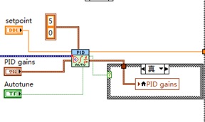
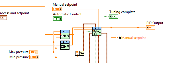
Your topology is not quite how we recommend that you make the transfer smooth. Can you do something like this?
Who will do manual setpoint pressure (units) and you need to update your gain, but it should follow. What is an option?
Maybe you are looking for
-
I have a Toshiba 40BV701 LCD TV, I put movies on a USB Pen drive, sometimes the TV will play the movie, sometimes we see the movie but can not play, sometimes plays the movie but with no noise, I can't get any more information on what the TV of speci
-
I need to take action once a file has been modified. I donot want the contents of the file to vote all the time. I can't verify ownership of the file modification time. Can I know how to do. Thank you.
-
Ideas: You have problems with programs Recent changes to your computer What you have already tried to solve the problem Remember - this is a public forum so never post private information such as numbers of mail or telephone!
-
I'm looking for on which runs in the background on my PC. After the start and saw the departure of the office, my PC will not go to standby or sleep screen. It takes a while to start and always meets the programs on my PC. (Office 2007). For any help
-
CMD disabled, disabled Regedit and gpedit.msc disabled/access denied to my school PC
Hey, I tried to enable CMD to the PC at school, then I looked at how to do it.Almost al the routes are blocked by admin. Regedit has been blocked by the administrator.gpedit.msc denies access.Virtually all the batch files do not work... Does anyone k