The PID control
Hello world.
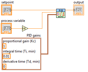
I wrote a program of temperature control in labview and used the PID Toolkit for it.
The entrance to the PID is the measured temperature and the output is a PWM signal fed to a relay that turns heater on or off.
The control works but I want the temperature to be stable within a range of + - 2%.
Currently, the temperature varies more than that.
IAM sure, this is the setting of the PID.
Because I have not worked with regulators PID Iam not exactly how to tune my system.
The best way I found is to zero I and D and make the system oscillate with P.
The only problem is that the system of temperature is so slow that it takes quite a long time to reach the set point which in turn would mean a lot of hours of tests only.
Now Iam just wondering if there is a faster way to set the PID controller?
Thanks in advance,
Best regards
Michael
I've used this method several times with slow heating appliances. It can take a long time to reach a stable temperature, but at least do not monitor constantly as he approaches this value.
In figure 3.4, Yes, the Min value is the initial value that is stable. It is OK to start an initial PWM output of 0, which speeds up the process, if your radiator is already at a steady temperature (the temperature in the room).
In general, the difference between the output of the first and the last values, better will be your control (you will get best results of going from 0 to more than 50% to 5%), but it will take more time to settle to a new value and of course you must ensure that you do not exceed the capabilities of your system. It's a good idea to have a separate alarm system in place that can cut power to heater if you exceed a temperature, especially if you plan to walk away from it until it stabilizes.
To a fixed cycle, the system will not continue to heat up indefinitely unless you have a perfect insulation without heat loss - but, as I mentioned above, do not choose a value that will not cause the system to overheat.
Tags: NI Software
Similar Questions
-
How do the dynamic set for the PID control point
Hi all
Here, I have a question about regulation PID setpoint. Now, I've built a program in which the vi PID setpoint. may not be a constant. But I want to improve the program by allowing the set to be dynamic, saying the dynamics, I want to say maintaining the setpoint change over time, it could be like a sine wave, or better could be a custom shape. Could someone tell me how to fill that?
Thank you
CJ
-
PID control with big delay in the process variable
Hello
My goal is to control the temperature via a valve and heat exchanger. I proceeded variable (temperature) measured from a hose. This temperature should be raised a few degrees with a heat exchanger. So basically I need to order a valve that allows the water to flow through the heat exchanger to raise the temperature to the desired level.
My original plan was to use a base PID regulation to operate the dispenser. However, it is about 0.5 to 1 minute of delay time in the temperature probe after I opened the valve, which increases the temperature. This leads to a situation where the PID regulation valve fully open during this period (trying to get the temperature rise). Then once the temperature begins to rise it fires quite quickly. PID begins turning the tap off almost immediately, but because of the time delay in the sensor, the temperature exceeds seriously. This led to severe oscillation and at worst unstable processes. I tried to adjust the PID control to "predict" the timer to close the valve in advance to minimize the excess, but failed.
I would appreciate if anyone has any ideas how to make this type of control with Labview PID functions. I also wonder if there is a better type of control procedure for this scenario as a PID control?
-Lars
This is a very common situation in the heating control, and generally PID can be adjusted to make it work. How do you do the tuning? If you do it by trial and errors, you have little chance to succeed. For a slow process with time delay, I like to use the method Cohen Coons, or similar open Ziegler-Nichols-loop method. The idea is that you temporarily remove or disable the PID. Set the valve in a fixed position and wait for the temperature to stabilize. Then, change the setting of the valve and record temperature at regular intervals data until the temperature is stable again to a new value. Use these data to get the initial values of PID using the equations provided by the tuning method you choose.
-
PID control cool instead of heat
Hello world
I had a quick question about the PID vi in labview. I use it to try to cool an a box (measured with a thermocouple) and maintain at a certain temperature. The PID controls a fan that changes speeds in order to cool the area. My problem is that when I ran, I noticed that he seems to think that he has to turn less in order to cool the area (in other words not turn). Whenever I put my temperature is superior to the temperature, the fan would work, but below, it would not.
The fan will always be in a framework where the instrument will be greater than or equal to the desired temperature. Therefore the PID of the fan should work to lower the temperature, not more. Right now he seems to think that it is more than a heating unit. Does anyone know how to do this?
Ed
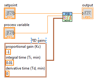
Try a negative gain factor. She will reverse the action of the PID.
-
PID control Windows THIS Labview application
Hello
I want to build an application that will control the temperature in ovens, using the PID command. The application will run in a controller (or a computer touch panel) with windows CE OS. I have Labview 8.6, the PID control 8.6 toolkit and Touch panel 8.6 module. The problem is that the vi PID does not seem to work on the touch panel module.
Is it possible to implement the PID control in a Labview windows CE application?
Thanks in advance.
I think that with a timed loop you can run a reasonable opportunity to 1 mSecond. I think 1 mSecond is the lower limit for the real-time systems like Windows/windows CE. And if you have the PID toolkit that will provide you with the features you need. You need not additional tools kit this PID. This because the touch panel module run under your standard Labview environment. But I don't know if the functions of the tool of PID like fuzzy logic are compatible with THIS. Have you also thought Windows Embedded as an operating system for your module. With windows Embedded, you can run standard Labview built of exe files
Both Windows Embedded XP Embedded can be dragged
http://www.Microsoft.com/windowsembedded/en-us/products/westandard/default.mspx
-
PID control tools installation problem
Hello
I installed the PID control toolset and a message indicating that:
"Error 1401. Could not create key. S...\Software\Microsoft. Check that you have sufficient access to that key, or contact your support staff. »
Do you know what I have to do?
Thank you
This error indicates clearly a Windows permissions error. It seems that your administrator has given you limited administrative rights (for example, a member of the power users group), then your best bet is to display the error message for them and ask that they install the software, or to give you the rights to install it.
EDIT: RF posted the answer at the same time...
-
How to reverse the action of the vi PID control?
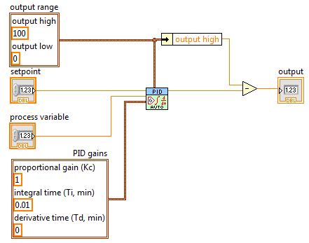
I want to control a starter that regulates pressure in a pump application. The application has already exists, but the customer wants the software to automatically control the strangler around a pressure setpoint. The operator controls manual, output scaling, feedback to the scale and the documentation refer all signals, as 100% opens the choke (corresponding to the minimum pressure), while 0% attempts to completely close the choke, corresponding to the maximum pressure. Basically, the process and the control variable variable have an inverse relationship.
I would use the PID of the Vi toolkit without modification. Apprently there is no built-in way to reverse the action of control. I want to show with some simplified diagrams.
First of all, I tried reversing the process variable, which I thought would just reverse the error of the PID equation and do what I wanted. But for some reason, he still pushes the output to 0 (under pressure) 0 set-point.
Then I tried reversing the proportional gain. This caused a very odd behavior, and he was always out of phase.
Finally, I applied a brute force - subtract the max value PID control variable. Because my control variable only goes from 0 to 100%, it works pretty well. Now 100% from the vi PID gives me 0% (under pressure) and 0% gives me 100% (completely open), which is what I want. For example, when the controller is enabled and the set value is 0% output PID readers choke at 100%, which makes sense. However, this seems cludgy.
Is there a better, more elegant way to invert the control action?
If you want to invert the response of the controller, multiply by-1 controller output.
It is also possible by reversing the proportional gain (as you've tried) providing the gain proportional acts on the controller-what he ought to do given the structure standard PID used in the toolkit blocks (see this thread which describes the structure used PID - as it confirmed OR control people).
Reversing the variable process only does not work, you will also need to reverse the set point - although if the setpoint is zero, it makes no difference.
Even if you have correct sign, there are a lot of things that can make the resulting behavior 'strange '.
-
How to properly temporarily disable all channels except one in the multichannel PID control loop?
Hi all
Help me please to solve the problem. How to correctly temporarily disable/enable all channels except one in the multichannel PID control loop?
Thanks in advance,
Oleg
Hi Oleg,
the entry "Car?" of the AdvancedPID is a table – as well as MS and pv entries.
So what's the problem say - / allowing for a control (aka of entry) instead of all loop?
-
State Machine with PID control
Hi, I currently have a problem with my state machine, I control two cylinders double effect in sequence that works very well. However, there is one point I need to increase the pressure in the cylinder and to maintain this pressure through the sequence of State machine, however when the state machine transitions to the next indicate the PID controller resets, how can I solve this problem? Everything in is also allowed to apply the pressure in the cylinder another (same node IO accessed).
Thank you I joined my project in a WinZip file, then it will have to be extracted. The two main VI to watch is 'Park Brake FPGA VI New' and 'park brake host VI update 2 "(new)
Thank you.
Nevermind I solved the problem with a parallel loop.
-
Hello
I have a loop of circulating water, and I control the temperature in the following way:
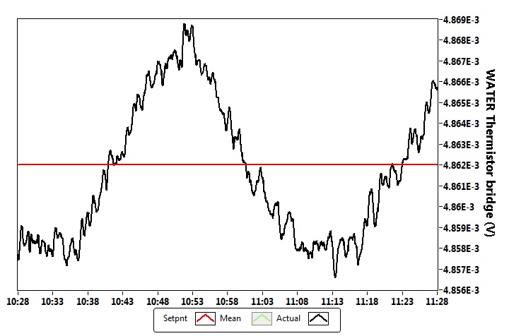
The sensor is a thermistor bridge, this bridge is driven with an accuracy of 5V reference (http://www.voltagestandard.com/New_Products.html). The output of this bridge is connected to a nanovoltmeter Keithley 2182. My LabView PID control (I bought the PID toolkit) drives a current source Keithley 2400 which is connected to a water - air heat exchanger Peltier solid state. On the side of this heat exchanger air is at a controlled temperature of the cabinet (air temperature stability is +-0.02 Celsius). The thermistor Bridge gives a signal of 50 mV/Kelvin to the excitement of 5V.
I have attached a photo where you can see measurement of a time data (sampling rate of 1 Hz). In general, I have a stability +-3rd-6 volt (standard deviation), which corresponds to the stability of Kelvin +-6-5.
I've set this PID command with the Ziegler-Nicholes tuning protocol standard, then first that I brought the stable oscillation system, and I measured the ultimate period time (1.375 minutes), and the nec plus ultra (147). The table Z - N gave to these values the following PID parameters:
P = 86.47
I have 0,687 min =
D = min 0,171
Overall, I am satisfied with my temperature control, but I'm looking for advice how to remove the visible oscillatory effect. This oscillation has a period of about 30-40 minutes, as you can see in the picture.
Is there something I could try to make my even more precise control? (it is also possible that I'm already at the possible gate given by the structural limits...)
Thank you very much!
Martins wrote:
Is there something I could try to make my even more precise control? (it is also possible that I'm already at the possible gate given by the structural limits...)
Can trace you to the output of the control loop (the value being written to the power source)? Specifically, draw out of the Keithley (if available), since the PID algorithm can output values with a finer resolution the Keithley can generate; Otherwise, around the PID output to match the resolution of the Keithley. See if the current alternates constantly between two specific output values, or if the output is continuously evolving during the swing.
What I think is happening, is that you have reached the limit of resolution of the power source, in this case, it will be difficult to eliminate this oscillation using PID, because the current source cannot output the exact value that you would allow to maintain the equilibrium temperature. If it does, the output changes between the two values from the nearest exit of you and you will always have a swing. You can try to increase the full gain (reduce integration time) to see if you can get a faster response and reduce the amplitude of the oscillation, but the trade-off is perhaps more great overtaking when you change the set value.
-
Reset the PID.vi only once on the State transition
Hello
I'm controlling a fatigue gear using LabVIEW test bed and I use the PID.vi to control the hydraulic circuit. During the transition from the start as a test State, I need once the PID (the integrated error) values to be reset during the transition. The current configuration constantly resets the PID causing the hydraulic output voltage to be lower than the set value. I can't understand how to be set to Boolean false to pass true during the transition from the State and then back to false to prevent resets of the other by default. I have attached the current revision of my code.
Thank you very much for your help!
Trace
It's a good idea, but it is not necessary to select blocks with the true and false as inputs, just equality by different and use the output directly to reset.
Also, I see that you have PID blocks in two separate cases. Note that those will act independently from each other - if you reset into a State, then move to another State, it will not be reset. Maybe it's what you want, and maybe it isn't, but be sure to put multiple instances of the PID block that control the same in different cases. You can also see weird integral questions when you place in case, if a long time share when you run the same instance.
-
For the PID variable time interval
Hello world
I measure the ph and control the flow of co2, so I decided to use the useful PID screw like I do for my temperature control.
the difference and so my question is, I have not want (/ power) to run the PID in a timed loop, in fact my intervals of measurement (eg. every 30 seconds ~ or ~ 60) may vary in the second range, because of the way I acquire data and how I put the valve in co2.
so my question is: is this a without problem?
I'm not sure weather the internal timer or providing the dt will explicitly be responsible for this?
(and I can't test it on atm equipment)
thx for your time
Shouldn't be a problem. Don't wire dt, let the PID to use its internal clock. Could make it more difficult to tune the PID, since you will have to account for the worst cases (longer delays between updates).
-
PID control using USB-6009, need of simple video or example vi
I have a new usb-6009 and have tried all the videos on the NC
Web site for practice. However with the version 8.6.1 I can't use
the pid simple vi which is used on the video. (its too old 5 x v)
I just need a PID simple vi to 8.6.1.so that day, I saw many complexes of vi
for the demo of pid... I'm creating control tools... too to choose...
any help looking for a simple vi or video? - as the demo shown
the NI USB-6009 Web site...
Concerning
JJ
Well, I did a simple proportional control for box usb-6009
with a time inside the while loop... don't know if it's the
Gourmet addresses... my sub PID vi is very simple...
But it shows how to use labview and usb-6009 for case
a loop very simple return PID...
Concerning
J
-
Hello world
I have worked on a project with labview since a few months now and I have reached a point where I need help.
Basically, this next part of my project requires me to drive a linear actuator to apply a force to the end of a tree, with a load cell between the actuator and the tree, giving me the real force applied.
I need to use a PID controller to maintain a constant specified weight on the end of the shaft, which in itself should be simple, but I have a problem with the way in which the actuator is driven.
The actuator is powered by a H-bridge which has 3 separate entrances to drive the cylinder:
direction = high/low 5v logic 0v low high
break = high/low 5v logic 0v low high
Speed = pulse width modulation
My plan was to use a PID regulator to adjust the PWM in H-bridge by adjusting its cyclical relationship between 0.10 0.90 (slow) (fast), then using basic functions of comparison between the set value and the process variable to control the direction and break logic. So, for example...
I want it to apply 5kg on the end of the shaft
my set point is 5 and the variable is 0, so labview applied logic senior management (to go ahead) and low logic at the break (to pass) and the PWM is adjusted to focus about to set.
I cannot get this to work however and I was wondering if there was a better way to do it?
I understand that it might seem unclear, so I hope that I explained well enough!
Thank you very much
HCook
hcook wrote:
The task of WOB speed, that is out of the PWM of the bridge: keeps telling me that the specified resource is reserved and will not work after my first race. This has something to do with the PID does not?
May affect the PID does not. Which DAQmx functions return the error? My guess is that it's the DAQmx Timing, which is probably not necessary. The task must already be configured for continuous samples in the project or measurement and Automation Explorer.
hcook wrote:
Also, when I run the program in manual mode, where I move the actuator manually by and adjust the weight based on the load cell signal, I get an error when I adjust the operating factor. He informs me that the PWM must complete a full cycle before the duty cycle can be adjusted. Now, the rate at which im changing the duty cycle manually are no where near the same speed a PID can adjust and it is why I am having the same problem in automatic mode.
What is your frequency PWM? Your loop rate must be lower than that to ensure that you do not get this error. At the present time that you use the loop at 100 Hz, so if the PWM is less than that, and you use a cursor (which can generate a large number of new values quickly when you move it) to control the market factor, you may see this error.
What is the purpose of DAQmx task accomplished in this loop?
-
The Gains of the PID VI Installer
Hey guys,.
I am trying to learn to use the PID VI in LabVIEW and programmed a simple VI. Here's the problem: the output of the PID VI seems only related to the Kc in the program and the other two values (Ti and Td) do not affect the output, for example ranging from 0.001 to 1000.
Is that all that I missed when programming?
Thank you very much.
Yes, of course, you can use a loop on the cRIO - you must use a loop if you want your code to be executed more than once. Make sure you put everything that should happen several times (for example, the function and control of front that you update while the code is running in the development environment) inside the loop. New LabVIEW users often put out of the loop and wonder then why they are only read once and never update again even if the code is still ongoing.
Maybe you are looking for
-
At first, I was told it was my video driver, but maybe it could be the motherboard. However, IE on the same pages of vBulletin does not horizontal black lines thin and thick, as shown in my screen shopt.
-
Re to make a photo book on my Mac
Hello, I recently finished and had printed a photo book. For some reason, I am unable to go back and do another because the pictures I used for the first are blocked somehow. How can I pledge them to reuse them? Thank you
-
After fornuis safari not works, the bar of los buscadores.
-
I don't find the control palette in my LabVIEW program more even if I go to view-> control palette. I rebooted LabVIEW, still could not find it. I'm using LabVIEW 8.6.1 right now. Could someone give me an idea? Thanks, Phuong
-
Question of printer model # ATC705EB
Just bought a new Acer computer and finish all hang on to the top but the printer. No place to fix the printer cable... I downloaded the manual and here, he says, I think, I need a memory card? You want to make sure before I buy one and find out afte