Boolean signal meter
Hello
I found a similar program I want to, but I did not insert in my VI, that... I need a counter who tell me how many times the Led market Boolean value.
My VI is attached
Thank you all
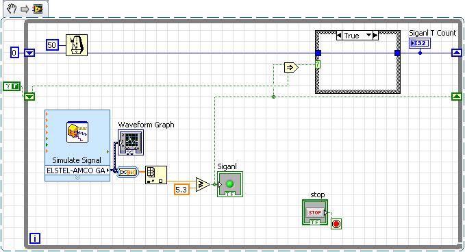
Jeff Bohrer says:
Your right!
I was counting iterations where Siganl was true.
I interperated put the post if the OP wants to only count the transitions
It works pretty well (invert the inputs involved and init the sr T to count negative transitions)
Tags: NI Software
Similar Questions
-
How do you plan the frequency of a Boolean signal?
Hi, I'm new to LabVIEW, so I suspect that it is propbably quite a simple problem.
I'm developing an optical tacometer to a model of gas turbine engine. I have a Boolean signal in labview which is move to a frequency between 4 and 26 Hz. I do need a live display of the frequency of this signal.
Does anyone know how I could do this? Any help would be really appreciated!
Thank you very much
Will be
This vi should work for you
-
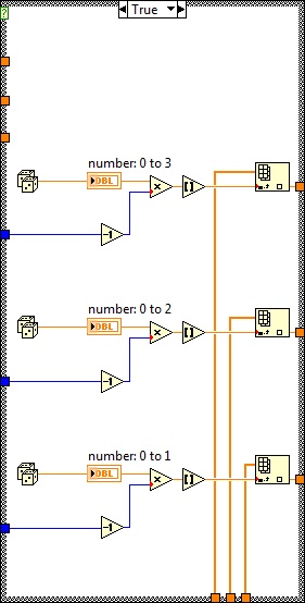
Generating unique random number with a Boolean signal on an RT target
Hello, this is my first time asking your question. I apologize if I post this question in the wrong Council.
[What I'm trying to do]
I am stable heating and cooling in an experimental space that I (with cRio9024).
And I'm putting a different experimental condition in space based on the function 'random number '.
'Different experimental conditions' sense different combinations of Tind, Twat_s and mdot (refer to the attached VI).
For example, if I get the Boolean TRUE signal.
I should have a set of [Tind, Twat_s, mdot] = [21,14,0.05], and IS this set of numbers until this Boolean signal goes to FALSE.
And when the signal passes to the TRUE once again.
I should have a different set of [Tind, Twat_s, mdot] = [24,16,0.15] for example.
[I]
Problem I am with my code is that,
When the VI is running, the random number remains the same as the Boolean signal is set to TRUE.
From what I tried so far for the last couple days, using 'the event structure' was the message more concerned that I found,
However, LabView help tells me that "structure of the event" on the objectives of the RT do not support the events associated with the user interface such as the façade of VI or controls panels.
I would therefore ask a quick help, since my knowledge of LabView is exhausted at this point.
This is so the part where I want to generate random numbers, WHEN this structure case is TRUE.
convert whole numbers, random numbers
Use them as a table index,
while I can choose conditions from radom to the given set of conditions.
Once more, I want to do is,
generate a SINGLE random number series when the structure above is TRUE.
Hope I have developed quite clear.
I'm appreciated for any kind of advice.
Thank you!
You just need to store the Boolean from the previous run. Then the logic would be (I'll call her Boolean previous B_prevand current boolean B):
If B AND B_prev > don't generate new values
otherwise if B > generate new values
Edit: to store your Boolean value, you can use a feedback node, or a loop with N = 1 and a registry change.
-
Simple question of LabVIEW on accountant Boolean signal off structure case
Hello
In my current program, I am trying to carry a Boolean signal (elapsed time) on a structure case to stop a while loop.
http://zone.NI.com/images/reference/en-XX/help/371361E-01/loc_bd_casestatus.gif
The loop on the left is basically what I want to do again every time I do this, I get a green tunnel box with a White Center. It I cannot run the program by saying that there is a missing assignment in the tunnel. What can I do to work around this problem?
White Center means that there are some cases where you do not have a Boolean value wired to the exit tunnel. The tunnel exit value is the value that is wired slots in the case that runs, a value must be available in all cases.
There are two possible solutions.
(1) [normally preferred wire] a Boolean value in the tunnel of release in all cases. Exit tunnel will then travel to a solid color.
(2) right click on the tunnel and select 'Use default if unwired' you will notice that the White Center will get smaller. It's like a constant false wiring for each of the cases with no wire. The drawback here is that it can hide errors in logic. You might expect over something, but not out of the Park, and no syntax error was reported.
Rod.
-
Battery meter or Signal Meter on the Application title bar
Not a matter of doing for me, but it would be nice to know if users must not leave my application to see this information.
I've seen several posts on this topic but nothing marked as resolved. I even did a text search on "Battery" on all my documents and I can't find anything.
I guess the battery and signal meter gauge are monitored on the theme. How can we add them to our application title bar?
Thank you all for the information AND the CODE.
This should be a great post for future programmers.
-
How to redirect the signal meter
Hi, I use Labview 2010 and 6212 usb Board. I'm generating a signal using counter 0 which, by default, output signal to PFI12. However, I want to signal to PFI2 or PFI3 for example instead of PFI12. The specimen vi that I use to generate signals is attached. Any help would be appreciated. Thank you, vk
Found the answer. Basically, I had to use CO. Pulse.Term property node as shown in the link below.
http://forums.NI.com/T5/counter-timer/counter-output-with-NI-cDAQ-9188/m-p/2218208#M10898
-
Switching with Boolean button meter/press/calendar status
I would like to have a button (Boolean) change the State of several digital output lines (photo attached):
A touch of the spirit, I want to create a short pulse (say 200ms) on lines 3 and 4 (simultaneously). After these 200ms, I want 1 line from the States (let's say it was OFF so far, switch on IT) and line 2 is the opposite (WE so far, go offshore). I want to press button to create this short pulse on lines 3 and 4 and switch on the line 1 and 2, States.
This could be a simple VI, but I couldn't know. I want to go to a data acquisition (USB-6211).
I hope I was able to explain it clearly.
Thank you bery much
-
Timed signal generation TTL with the NI USB-6501 to be read by Arduino Uno
First of all, I want to apologize - I am very, very new to LabVIEW and brand new to the development of the software of control equipment in general. I tried to find an answer to this question already, but I'm not entirely sure what I'm looking for.
I have currently a work program LabVIEW which operates a gun card NI USB-6501. Due to the nature of having a machine that springs from a powerful beam of electrons, we want to assure you that if the computer controlling stalls or fails for any reason, we have built-in security that can stop the gun. Our current idea is to connect an Arduino Uno on a PIN on the USB-6501 and LabVIEW to generate a timed signal, which may read the Arduino. If the signal fails (indicating that the control computer has queued or off), the Arduino triggers a power relay that is independent of the control computer and turns off the gun.
I understand that the USB-6501 operates on TTL signals, so the signal that I should be something in the sense of "output TTL high, wait 1 second, output low expectations, a second, repeat TTL ', but I have no idea how to go about programming in LabVIEW. My first thought was that it is a square wave by using the function "simulate the signal" output, or to have trigger an iterative Boolean signal, by using the function 'DAQmx write', but I don't really understand how do to implement or another idea, or if an idea would even work.
Any advice would be greatly appreciated.
Hi Elizabeth,.
THINK THE STREAM!
When do you DATAFLOW think everything falls in places!

Several problems:
-You have to put that MAKE impulse VI in his own loop parallel to your main VI!
-When you place this generation of impulses in the effects loop ("TTL arduino low-high") you should put the CreateTask and StopTask outside the loop: no need to create/stop the task in each iteration.
-Why are there points of constraint to waiting functions?
-Why is there bent wires? You know Ctrl-U?
-LabVIEW comes with an extensive library of example screws: you looked at all these examples DAQmx?
-Suggestion: Learn more about the "structures of producer-consumer"!
-
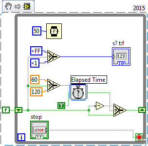
I need to order a heating appliance to be switched on for 60 seconds and then be off for 120 seconds, and then the operation be repeated for a number of cycles. My main loop works continuously with a delay of 50 milliseconds, and needs a Boolean signal from switch continuously, so there is no possibility to place a hold or time out function in this loop. When I try to call a Subvi, which has a delay, the output of my main loop would be delayed. Anyone would be able to recommend me in the right direction.
Do it like that. It initializes the value False, after time, happening to True, and so on.
This could use some cleaning with nodes Select, but it does the job. The result is False for 120, then True for 60 seconds, rinse and repeat.
-
Greetings,
I need a Boolean control that will write the measured data in a text file while it is lached and do nothing while it is unlached (which is easy). However, I also need to display a dialog box when it is lached first to invite the user to add to an existing file or create a new file. How should not prompt the user to select new or add is lached. It should reprompt only if the Boolean value was unlached and relached.
Any ideas? I tried several different approaches, but everything I've done has not worked at all or will cause invites at lached.
I know it will be a record time difference and at least a boolean comparison, but I can't understand the arrangement.
Thanks in advance.
Hi BB,
examined the functions of the Pt-Pt. You will find a ready-to-use VI to detect the edges of a Boolean signal!
Or use this Boolean math: RisingEdge = signal [n] AND NOT (signal [n - 1]). (Here you have the Boolean function has already been mentioned with a shift register...)
Everything you need to opens the dialog box for the rise of the Boolean signal edges...
-
Boolean values of multiple digital inputs
Hi guys,.
It must be really basic but I looked around to find a solution with no success...
I have a digital input with multiple-entry device.
For example, I read signals 0-24VDC of pushbuttons and limit switches.I would just like to be able to assign to each entry to a Boolean to use anywhere in the code variable.
Example: I install the DAQ help and get the usual result of 'data '. I'm guessing that this generates a table of Boolean signals.
How to convert this table in a single Boolean DI signal for each entry?
Or better yet, is there a VI I should use that emits individual signals?I also have the same problem for outputs digital. I'm guessing that I'll be able to apply the same principles to the problem well.
Sorry if this is obvious and my thanks for the help.
JoelIndex table will collapse a table into individual elements.
Build table opposite taking individual values and build in a table.
I recommend you watch the LabVIEW tutorials online
LabVIEW Introduction course - 3 hours
LabVIEW Introduction course - 6 hours -
How to create a Boolean value when it is activated, it is an iteration and then off the back
Hi all
I could not explain well in the title, but I try to order a device that only requires a single click to move. For manual operation, a switch locked like OK button would do, but I'm trying to automate it.
For example, if we have a digital control and a ' equal to '? a Boolean that is connected to an indicator. for example (if the number is = TRUE then 10) the indicator would remain on until what this number changes.
But when I try to get, the led lights for iteration, then off. In addition, when I change the number to something is, I want the indicator also turn on then.
If it is resolved, it would be useful to make the device to receive a SWITCHING signal to turn on once #1 is selected, and when I change the option he will receive another SWITCH to disable the #1 option.
Your help is very appreciated!
Hi malmureeh,
you want to detect the edges of a Boolean signal, like the rise of the edges.
There is a function of ready - to-available employment: BooleanCrossing!
-
How to store values in excel usinglabview
I am currently the work of digitization of the resistance of a keithley 2700 DMM. I got the value of the resistance by using the only measure VI. But what I need is whenever I have call keithley analysis based on a signal meter, should be given the value of the resistance. And all of these values should be saved as an excel file after the other, as well as the number of cycles. I enclose my current VI. Here, I had the 2 outputs required, but I couldn't import them into excel one after the other. Please help me. NB: here, I have considered a Boolean switch closed as my meter signal.
Hi grugh,
First of all expectations put in your loop.
See example as reference.
Let me know if it helps.
-
Satellite L755 - card wireless driver is corrupt
My Satellite L755 was fine yesterday, but this afternoon it started with this disturbing of the yellow dots on the wireless signal meter in the status bar. I ran to the resolution of problems, followed her, and that is to say that the wireless or LAN driver is corrupted. I checked, it is an Atheros chipset, so I got a mate to download the latest driver on the site of Tosh.
I transferred via an sd card, and it's an Assistant auto running. He ran, the pilot has changed (I checked the dates), but the laptop has exactly the same problem. I know it's windows, as on the start screen, where the windows password box appears, there is a WLAN box and who is showing the complete connection.
What should I do now? The final move would be to transfer all data on an external drive and go to the total reload of windows on the recovery partition, but it would be a radical gesture.
Anyone has a suggestion for a less stressful recovery?
Wireless network adapter installed and listed correctly in the Device Manager?
Try please restart your router and check the connectivity again?
Is visible WLAN for your laptop after reboot of the router?Try please test with some other WLAN or your WLAN WLAN functionality but without WLAN security.
Post comments. -
Hello
I am trying to connect my sbRIO 9636 with my PC via CAN and I have several problems. First of all, where can I find the communication button CAN fire at the Labviews (picture1) block diagram Panel? I have GOT (input analog), AO, DI, do... but not CAN.
Then I need to send and receive via the different signals CAN (receive: 42 voltage signals, signals of temperature 12, send: 42 Boolean signals). Does anyone have any example or something similar to get started? can someone help me please?
I am new to Labview and I need to get this working!
Thank you
If you are missing items palette you can either do a repair install of these toolkits, or perhaps those who have not been installed in the first place. I've never used this material or this palette so I don't know what package installs these tools.
Maybe you are looking for
-
Replacing the battery warranty
* I had my lap top for 8 months and a few weeks ago I noticed that I was getting notifications he had a problem with my battery performance *. * Now, the my battery is not high at all... *. * I thought I had read that the warranty does not cover the
-
I allowed access to my computer?
I received a phone call from a man claiming to be Windows 7 support. He said my computer was corrupted, and I should press control and the button Windows flag, a. I did, but it did not show what he says, he would. He then said I should go to www.ammy
-
I'm looking for a dock for my Fuze. The Griffin deal does not seem to be available in the United Kingdom and the United States delivered makes costly (and takes over the limit for VAT, rights and customs of customs clearance fees, adding subsequently
-
gives me "communication not available" message and the printer does not print dell v305
My dell v305 printer worked. He started giving me this "communication not available" message and it stopped printing. I uninstalled and reinstalled the printer software and I changed the printer cable. Nothing works.