Boolean values of multiple digital inputs
Hi guys,.
It must be really basic but I looked around to find a solution with no success...
I have a digital input with multiple-entry device.
For example, I read signals 0-24VDC of pushbuttons and limit switches.
I would just like to be able to assign to each entry to a Boolean to use anywhere in the code variable.
Example: I install the DAQ help and get the usual result of 'data '. I'm guessing that this generates a table of Boolean signals.
How to convert this table in a single Boolean DI signal for each entry?
Or better yet, is there a VI I should use that emits individual signals?
I also have the same problem for outputs digital. I'm guessing that I'll be able to apply the same principles to the problem well.
Sorry if this is obvious and my thanks for the help.
Joel
Index table will collapse a table into individual elements.
Build table opposite taking individual values and build in a table.
I recommend you watch the LabVIEW tutorials online
LabVIEW Introduction course - 3 hours
LabVIEW Introduction course - 6 hours
Tags: NI Software
Similar Questions
-
the value of the digital inputs to change the field
Hi all
I have an edit field that has a digital text filter that only accepts phone numbers. Users have the choice to load these numbers from address book or direct entry.
I used the digital filter to allow only numbers. .
But when I tried to load these address book. with editField.setText (phoneNum); It is to throw IllegalArgumentException.
How to set digital inputs to the editField?
Hi thanks for all your entries!
My issued are resolved. I used BasicEditField aulieude EditField to solve this problem. the basicedit field allows the digital text and it solved the problem.
Thanks for all your interest...
-
arbitrary hotkey to toggle a Boolean value (or increment/decrement a digital)
Is it possible to assign the space bar as a shortcut to toggle a Boolean value from one State to the other (i.e. after the tab using FP and affecting emphasis as boolean)? More generally, is it possible to assign any key as a shortcut to a Boolean value (or a digital for its actions to increment/decrement)?
The Advanced > button Navigation... Panel does not provide this option that I see (LV 2009 SP1).
Thank you
X.
You can't assign arbitrary key to this action. What you can do, instead, is to use a structure of the event to intercept a key event and react accordingly. See attached example (LV 8.2).
-
How to pin "Info button" Boolean values of the input data to acquire?
I am a newbie to LabVIEW. I did this VI referring to this ARTICLE http://digital.ni.com/public.nsf/allkb/CA411647F224787B86256DD000669EFE
I have problems with taking the values of these pines "Info"... As the functions of 32 buttons, 4 Directions, 8 info axis are wired to 3 Pins?...
In fact, the goal of my project would be this...
1 initialize the Joystick
2. reading axis and Info button
3 assign characters for each button (a Boolean value) and the axis (-32768 or 32767) as button 1 = Servo1, button 2 = Servo2, Y-Axis(-32768) = MF, Y - Axis (32767) = MB,
X Axis(-32768) = ML, X-Axis (32767) = Mr... etc...
4 send the characters to an Xbee Pro connected to the PC with a USB Dongle of Xbee.I know it's simple, but such things of convertion and the 'thing' entire component is really confusing... Kindly help me out to the point 3 & 4
These are clusters. You can simply use the Ungroup by name in order to leave the values of the components.
-
With the help of digital input for Boolean control?
Hello!
I have spent a lot of time to search but have not found a solution to this...
I have LV 2015 with chassis NI 9188 and module NI 9425 DI. Try to use the input signal to assign a State structure machine program and/or events in real time. It would be acceptable to have an indicator show the status of the input line, since I can use it elsewhere with Value (Signaling).
Please do not ask for the code - the problem is quite simple. I just want to use the digital inputs to program control as a T/F. I want just the program to analyze the State of the input and decisions - a bit like a PLC.
All I seem to be able to extract is data of digital waveforms with a task DAQmx.
It's not a trigger - I already use a trigger to start the analog acquisition.
Formulate the problem in a simpler way... What to do if you had a digital input module and you wanted to see the status of each input line in the form of a LED on your face in real time. How would you do it?
I really appreciate the help!
greyhorn23 wrote:
Formulate the problem in a simpler way... What to do if you had a digital input module and you wanted to see the status of each input line in the form of a LED on your face in real time. How would you do it?
I would like to write what has been read to the Terminal.
From what I can tell, you want to just read a single static value from your digital line. You can then simply read the value of one and do some logic with her.
-
Help! three digital controls by three Boolean values
Hi guys, I really need your help. I am trying to create a program where I can choose the button (A - Z and 0-9) keys three keypad and use in order to increase the 3 individual respective Boolean values into the light. I work for a while now. Here's my program: manvery - happy:
Tissue wrote:
When I select 'a' of the digital list and I press the keyboard boolean unlit 'a', turns on him. When I press "a" again, the Boolean value lit will be unlight. While the program still works, I can always choose a different as key '5' and the other '5' key it will switch again when I pressed on it...
Try something like the joint (LabVIEW 2011).
By pressing one of the buttons (case insensitive) made alternate value Boolean coresponding. Change the selection will clear all indicators. Modify if needed.
-
Best way to encode several digital inputs of choice / binary indicators
Hello.
I need some suggestions.
We have several libraries API (to control our material) written in C and distributed as a dll. For many of them, we have a library of LabVIEW VIs wrapping (using the call library function node).
We have several functions in which the entry (in the original C library) is an unsigned integer, which is supposed to be several flags ORed together (each value one bit).
I've seen more than one title, that this interface has been transferred to the wrapper live
1 digital input. User must understand and use it exactly like the C programmer
2 try to make more enjoyable - an entry that is a table, which appears on the front panel, as a sort of list box multiple choice of entry (internally in the block diagram that is used to create the correct entry to the C function)
I think there are others, but this is what I remember right now. When I saw option number 2 (looking at the front) I thought it was much more enjoyable. clearer and more intuitive (the user can select choice named, no, not strange %valeurs hexa%, etc.). However when I put on a block and tried to wire diagram, I had to provide an array of numbers; I had no idea what the values were supposed to be. Option 2 seems so much better for a user interface, but for an API, I think it's actually worse.
What do you see, if you were a programmer building my functions into your application?
Thank you.
Batya
Since each value is a bit simple, I would say that the wrapper have Boolean values in the connector pane and convert it internally to the correct bit field. Another option is to use a cluster of Boolean, but which may be less friendly to the user of the API. I suggest you do this only if you have several options.
-
Hello
I'm learning about labview data acquisition. So, I made a base for digital vi, with a virtual digital input device. For some reason any I can not output anything other then zero, but when I run the daq assistant (when you install assistant daq) Boolean values between 0 and 1. But, in my VI I can't get any other input then set to zero.
I enclose my VI.
Thank you
You should associate your stop button at the entrance to Stop on the DAQ Assistant. You are openening and close the task each time when you do not do this. According to me, which is also reset the activation/deactivation of the simulated device.

-
Increment and decrement with a Boolean value entered
Hello Experts Labview (and in fact life savers!)
I have a digital controller (button) in my VI, digital indicator, in addition to a Boolean of power input.
As an initial state, the digital display will contain a certain value (zero for example) and will only receive the variation in the button entry as long as the Boolean is true, and then add it to this initial value.
What is the change ? lets say that the button was on 8 before I touched the Boolean true, the value of the indicator is zero, and then I hit the Boolean true.
Now, when I move the button from 8 to 18 years (variation of + 10) , I want to receive the indicator + 10 and add it to the zero, now the result is 0 + 10 = 10
Now, the value is false, I move the button and nothing happens to the in the indicator 10.
Now, the Boolean value is true once again, let's say the button was about 4 at the time, I hit the Boolean true and it spend 4 to 1 (change-3) , the indicator value will now be 10 + (-3) = 7
I hope I explained the idea in a clear manner, I would be very grateful if someone could help me with this.
P.S. I have attached only the vi to illustrate the idea.
Thanks in advance
You care only remarks how the button changed. Therefore, you must subtract the old value and the new value to get how to change the button. Then add inside the structure of the case, this difference to your value that belongs in the registry to offset.

-
Raising an event based on digital input? Treatment of a condition of emergency stop
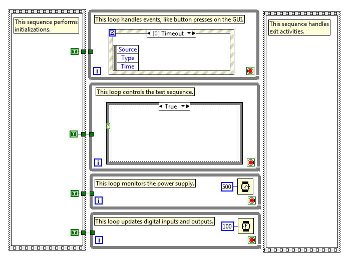
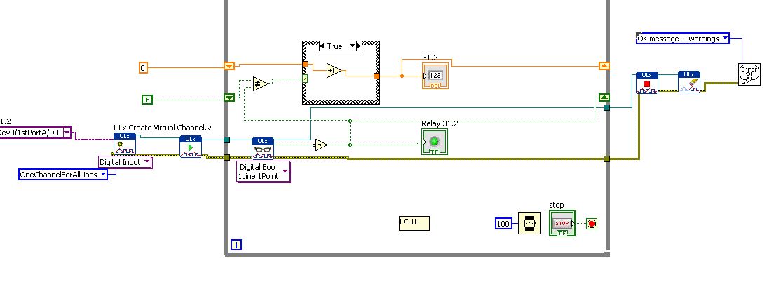
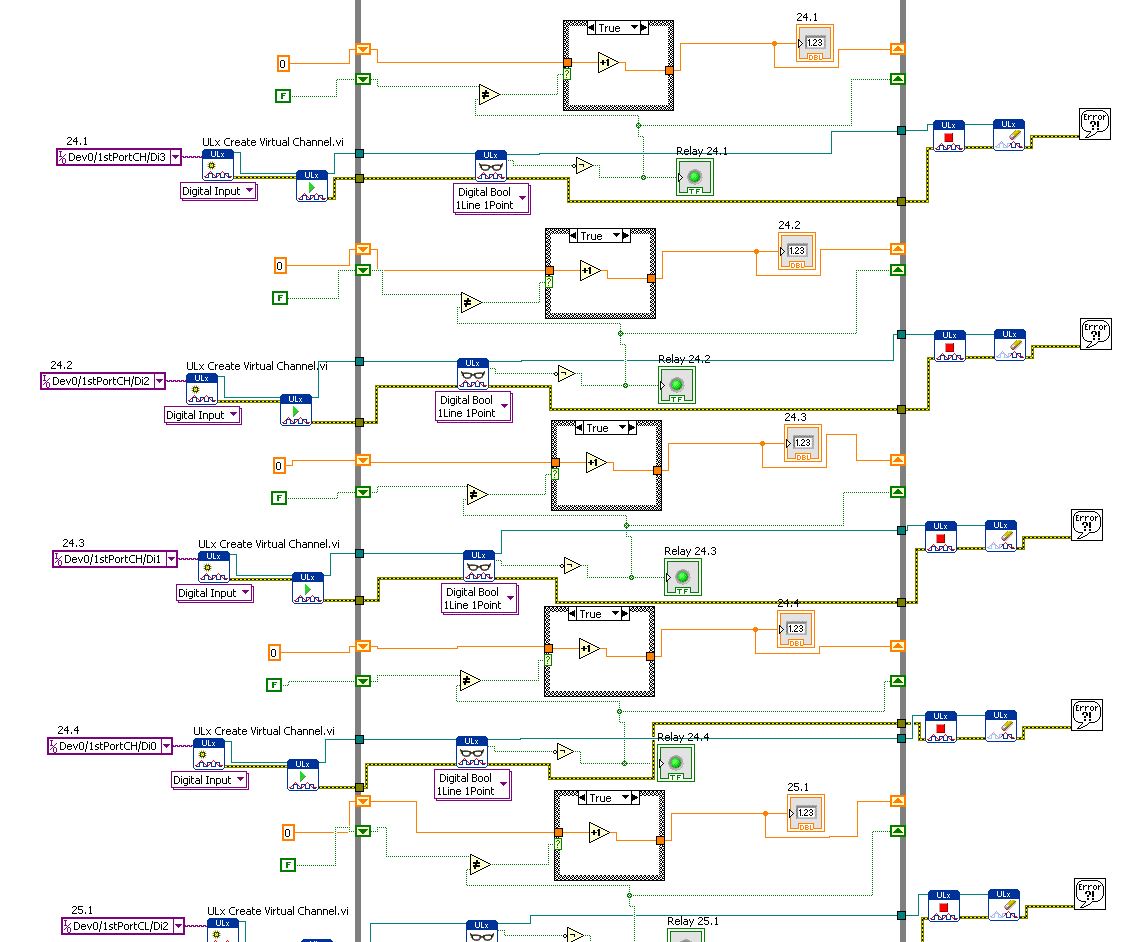
I'm working on a test sequence into LabVIEW. I have a security which I am followed by a digital input the relay status, and I would like to pass to my failed state that I am in a State of emergency. (In my case, this happens when a barrier is broken or emergency push button is pressed).
It would be easy to do if I could use a digital input to trigger an event. However, this doesn't seem to be possible. I tried bind my digital input to a control, and then follow the State of the control as an event, but that doesn't seem to work.
My main problem is that I can be in one of the stages of test 5 seconds approximately. So far, I have not found a way to out or interrupt this step if my digital input changes state. I can get it to transition to the failed state after the step in progress, but I want that it to transition immediately when the safety relay is broken.
I've attached a picture that shows the basic structure of my program. The actual program is much more complicated, so I hope this is enough information to get started. I have stops in each loop attached together with the help of a subvi, which basically returns a Boolean TRUE if you press the 'stop' on the operator interface (it is one of the events of my structure of the event).
It seems that it would be a fairly common situation that there must be some answer I'm missing. Can anyone help? Thanks in advance...
You need (somewhere) a loop that monitors the digital status and can detect the transition Fail. The timing of this loop of 'surveillance' apply to how fast you can respond to failure.
But now you need to trigger an event when this happens. When I started programming in LabVIEW, I learned on the events of signs of value that could trigger programmatically a value indicator has changed. However, a few years later I learned the user events, a more flexible method for generation "software interrupts' who have a number of advantages over value of signage.
I don't know if you are looking for using LabVIEW or LabVIEW examples user events you'll find a good explanation for how to use these (use the Help Index, and then type user name).
Bob Schor
-
3 digital inputs for the structure of the case
I'm in the early stages of development a VI that will monitor 3 digital input lines. Only a single digital input will be active at any time. For each digital input, a VI runs under different. Currently, I use 3 structures distinct case (attached).
Is it possible to use a case structure (3 cases over a default value) to monitor three digital input lines? Specifically, how to convert Boolean data (digital input lines) to a data type recognized by the terminal selector?
Thank you
Bill
Adding to my post from yesterday.
In defining an enum for each possible value with a descriptive name, it is easier to follow what the code is doing.
The attached VI (7.1 LV) shows how I could manage three types Boolean controlling a press to ensure that security is set, and the part is in place when the operator chooses to activate the press.

This approach allows you to treat each of the 9 possible States only.
Of course, this approach is not feasible for more than 5 bits (Boolean) (unless you have an intern to the
 no, not me!)
Ben
-
How can I set up a digital input task to read continuous samples?
I am trying to create an exclusively digital task that will make digital readings at a rate timed by the material using a PCIe-6509. However, when I try to put the task timing as follows (which works on a PCIe-6509), I get the following error:
Requested value is not supported for this property value. The value of the property may be invalid because it is in conflict with another property.
Property: NationalInstruments.DAQmx.Timing.SampleTimingType
Required value: NationalInstruments.DAQmx.SampleTimingType.SampleClock
Possible values: NationalInstruments.DAQmx.SampleTimingType.OnDemand, NationalInstruments.DAQmx.SampleTimingType.ChangeDetection
Task name: DigitalInputTask
State code:-200077
The relevant parts of my code are:
public class DigitalInputReader: IDisposable
{
public DigitalInputReader()
{
dataReadyHandler = new System.AsyncCallback (DataReadyEventHandler);daqmxTask = new DigitalInputTask();
daqmxTask.Configure (Globals.NI);daqmxTask.Control (TaskAction.Verify);
daqmxTask.Control (TaskAction.Commit);daqmxReader = new DigitalMultiChannelReader (daqmxTask.Stream);
}public class DigitalInputTask: task
{public DigitalInputTask(): {base ("DigitalInputTask")}
public virtual void Configure (NiConfiguration niConfig)
{
<= niconfig.digitalinputs.count="" -="" 1;="">
{
String physicalChannelName = niConfig.Device + "/ port" + niConfig.DigitalInputs [i]. Port.ToString () + "/ line" + niConfig.DigitalInputs [i]. Channel.ToString ();
String nameToAssignToChannel = niConfig.DigitalInputs [i]. Name;DIChannel ch is this. DIChannels.CreateChannel (physicalChannelName, nameToAssignToChannel, ChannelLineGrouping.OneChannelForEachLine);
c. InvertLines = niConfig.DigitalInputs [i]. InvertLines;
}
var signalSource = "";
This. Timing.ConfigureSampleClock (signalSource, Globals.MachineSettings.SampleRate, SampleClockActiveEdge.Rising, SampleQuantityMode.ContinuousSamples);// Globals.MachineSettings.SamplesPerChannel);
}
}The last call to Task.Timing.ConfigureSampleClock, it's which throw errors.
Of the options available, or SampleTimingType.OnDemand or NationalInstruments.DAQmx.SampleTimingType.ChangeDetection provide the same precisely timed calls that I am familiar with the analog input interruptions.
How is it possible in a digital task? I mean, it seems that I could set up another task to do call by material for the production of a clock signal and use the ChangeDetection synchronization mode, but this seems a bit complicated for what should be easy to do. What Miss me?
Update: I thought about it. You cannot call ConfigureSampleClock when the digital input card is a device of 650 x, because these devices have any automated examples of clock. They are configured to run in mode default finite samples. You must make all sample synchronizing with these devices in the software.
Be cautious, however, because the .NET timers ensure they put any faster than their scheduled interval. In practice, they are usually 5 to 10 ms slow by tick. This means that if you want to read samples every 100 ms by sample clock, you'd end up reading all 108 ms samples. All counters based on the elapsed time and number of samples would be away after a few seconds of it.
Instead, you must do one of four things: write a doggone driver that runs in ring 0 and interfaces with the PCIe card in the required interval (i.e. on NC, not you, in practice), tolerate the inclination of the clock, use a multimedia timer as an interruption audio or video that is more likely to respond to the correct interval, or , my solution, an accurate clock allows you to set the interval of the timer. I wrote the following code to the timer:
var CorrectiveStopwatch = new System.Diagnostics.Stopwatch();

var CorrectedTimer = new System.Timers.Timer()

{
Interval = targetInterval,
AutoReset = true,
};
CorrectedTimer.Elapsed += (o, e) =>
{
var actualMilliseconds =;Adjust the next tick so that it's accurate
EG: Stopwatch says we're at 2015 ms, we should be at 2000 ms
2000 + 100 - 2015 = 85 and should trigger at the right time
var StopwatchCorrectedElapsedMilliseconds = newInterval +.
targetInterval-
CorrectiveStopwatch.ElapsedMilliseconds;If we're over 1 target interval too slow, trigger ASAP!
<=>
{
NvelIntervalle = 1;
}CorrectedTimer.Interval = NvelIntervalle;
StopwatchCorrectedElapsedMilliseconds += targetInterval;
};I hope this helps someone.
-
How to combine several digital inputs for playback?
Hi comrade Labview users.
I just started using LabView and I am very new to it. I know him understand how it works and you have something to work, but I need to be more effective.
I use DIO96H - USB DAQ Measurement Computing, which includes 96 digital inputs. I use the DAQ to acquire the activations of relay and record the number of times the relays flips.
Basically, I created a digital input read and then copy & pasted 95 times... it works but I know that's not the best way to use LabView.
How can I change the digital input (Di1/1stPortA/dev0) in multiples so that it iterates through all 96 channels without copying and pasting the same pattern over and over again?
Leon
You have the correct polymorphic instance for playback? Once again, for the material OR it would be a NChan Read. There should be a similar choice if I remember correctly.
-
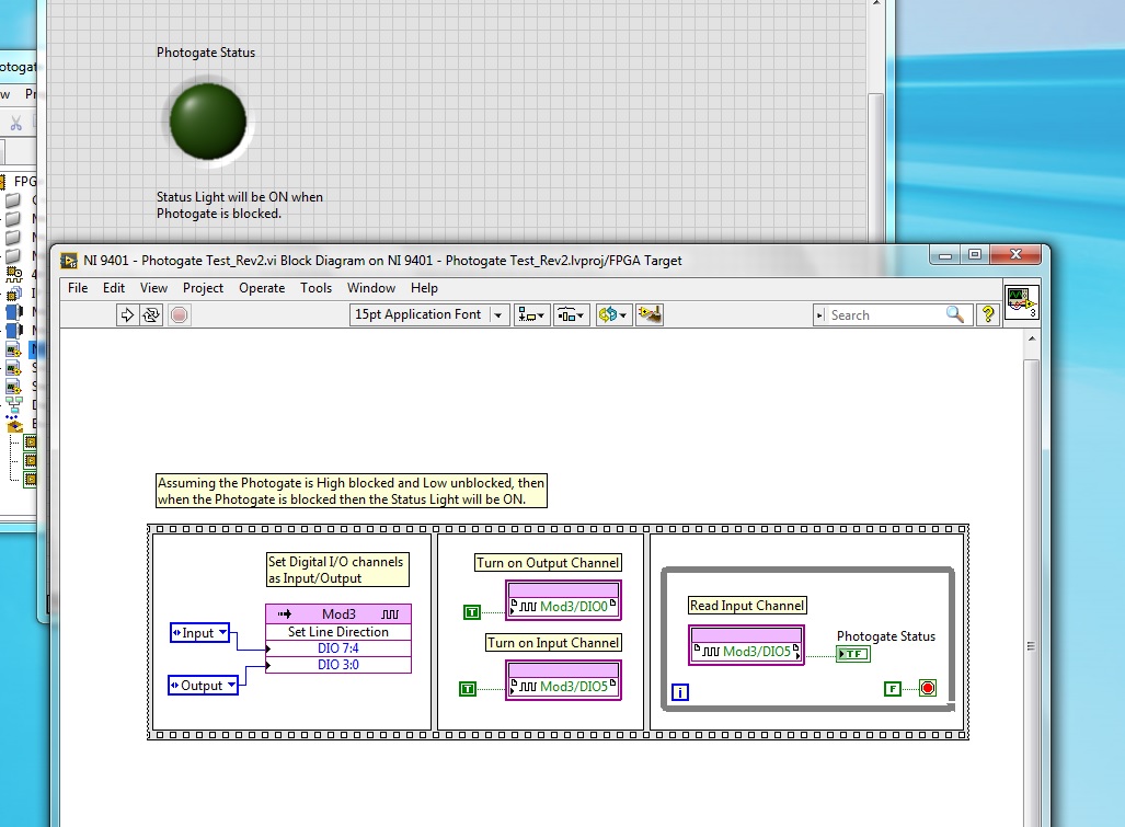
Playback of digital input [FPGA] - NI 9401 - questions?
I'm having some trouble with the digital input NI 9401, which is to have a uniform reading. I have a photogate that power of a digital output is turned off and goes in to a digital input module, but I can't read the entry several times. My LED flashes once and never again will blink until I restart my CRIO or recompile. I have launched the ports of entry and exit, their market and constantly for loop. Any idea what's going on?
Hi Allan,
Why you "light up" a channel of entry?
Writing a value to a DIO PIN is usually for outings!
What is connected to your PIN DIO 5? Have you checked the entry with a DMM measure?
How long the impulses are measured with this entry? Do you really you can see short pulses of light flashing?
-
A global variable is adjustable, and a Boolean value in LV3.1.1?
A global variable is adjustable, and a Boolean value in LV3.1.1? I can do in LV 8.0, but 3.1.1 I need because of instrument gives me the penalty.
All suggestions from users for a long time?
Well, I'm a long time user, but that will come back some time.

A global variable is basically a VI without a block diagram, so you should be able to place a Boolean control on the global variable just as you would place a digital command. Boolean values are treated differently at the time, but it probably won't affect what you do. The prices you say you tried, you can't put a Boolean value controlling this? I honestly don't remember not that is the case, but if this is the case, you can still use the functional overall construction, which is what we did before global variables have been introduced.
Maybe you are looking for
-
How to reset an iphone 4S which was given to me and they do not know their apple account
They gave me an iPhone 4s to a friend, the iPhone is disabled and I need his email/password to connect to the device and he forgot, is it a way I can completely reset even though everything on gets them lost?
-
my hp pavilion g6 stopped working suddenly and it shows me a message that says: NOT FOUND BOOT DEVICE PLEASE INSTALL AN OPERATING SYSTEM ON YOUR HARD DRIVE HARD DRIVE (3FO) SYSTEM DIAGNOSIS I'm so worried now if I lose all my files on my laptop! Plea
-
failure of migration on wifi. error message: migration quit unexpectedly. Apparently, the migration is yet complete, but with a lot of mistakes. many programs on the new computer do not work. anyone else having the same problems? never had any proble
-
Sha1sum/MD5 for test of Windows Server 2012 R2 Essentials
I try to install the above https://www.microsoft.com/en-us/evalcenter/evaluate-windows-server-2012-r2-essentials version, file name 9600.16384.WINBLUE_RTM.130821 - 1623_X64FRE_SERVER_SOLUTION_EN-US-IRM_SSSO_X64FRE_EN-US_DV5. ISO. When attatching the
-
I wonder if more shared video memory will make my game to live better.
allright, I have a Core 2 Duo 2 ghz cpu, 3 GB of RAM DDR2, an Intel GMA 4500MHD (128 MB dedicated video memory) and 1.2 GB of video memory shared (you know, the kind that comes out of your total RAM and is SLOW). I play games (halo 2, call of duty),