BT 6.1 feedback node?
I have an old map OR old that I use, it is an ISA PC1200 card, I only got to work with LabView 6.1. I have a very simple question, and it's driving crazy me. I have a WHILE loop running action. In an iteration of the loop, he solves a number. How can I keep the number of the next iteration of the loop? In a more recent version of LV, I used a feedback node to do this, but I do not see 6.1.
It's a simple thing, but I can't find the solution. In a BASIC program that it would simply be a variable. Any ideas?
6.1 there shift registers? Right-click on the left border of the while loop and see if the shift register to add is an option.
-AK2DM
Tags: NI Hardware
Similar Questions
-
Feedback node initializer ignored?
Hello
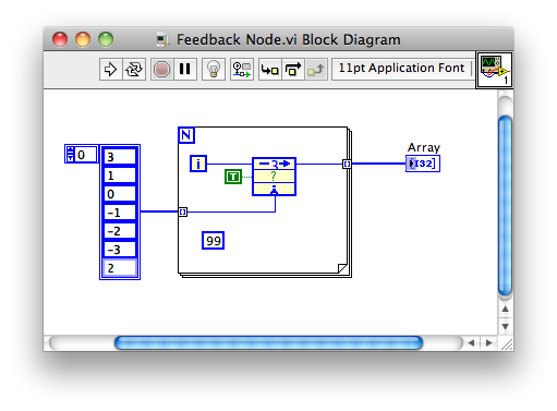
I have a feedback node sitting in a loop, the number of iterations is determined by a table of entry. The same input array is connected to a terminal of the initializer of the Feedback node. The delay of feedback node is equal to 3 and still output the node contains only the first value in the array for the first 3 iterations. It is easier to show than describe them.
So I expect the output array to hold the values 3,1,0,0,1,2 and yet it actually contains 3,3,3,0,1,2
If I have the scalar value 99 wiring to the initializer then I get the EXPECTED 99,99,99,0,1,2
What Miss me?
It comes to LabVIEW 2011 for MAC OS X
To develop the Swatts answer a little more. You are in fact only during the initialization of the feedback with a single element node because you have the array of automatic indexing in the tunnel of the loop.
If you powered the table in its entirety in the loop For and the initializer of terminal, the way you would expect it would have worked.

-
How can I programmatically set the delay of a feedback node?
I'm generating a sine wave using the vi simulate Signal Express. I then use a feedback node to delay the signal of a specific amount. The front displays 2 charts: one of the original signal and another of the delayed signal.
The problem is that I will determine the amount of delay based Boolean user entry rather than having to set by using the configuration box (the time will be 4000 if the user chooses "real" and 2000 if the user chooses "fake". I do this with a box structure. How can I use the delay printed by the case structure to control the delay of feedback node?
I'm relatively new to Labview, so maybe there is a better way to reach my goal of using a Feedback node. Any ideas are appreciated!
Take a look at this response, "Is there a period of dynamic for nodes of z comments?"
-
strange behavior of feedback node
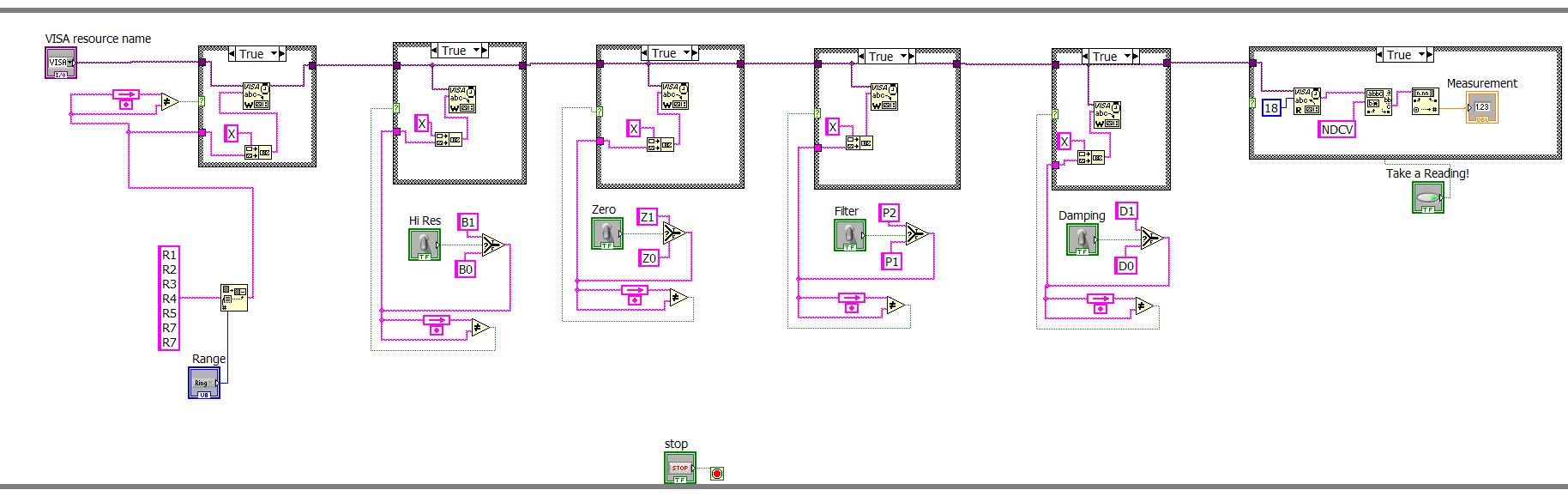
Until recently, I discovered the nodes of comments, and I'm trying to use them to control my instrument, so that if I change a setting, comment nodes can see the difference and preforms an entry visa. There are 5 parameters to control, 1 to select a range in a list and 4 switches (Hi Res, zero, filter, depreciation).
The problem is that everything works, but the instrument itself is always one step behind the front panel. That is, I press the switch to Hi Res and nothing happens, then I flip another switch, say the depreciation, and Hi Res then responds. Then I flip another switch, then depreciation resonds. The switch controls the correct setting, but it is still behind by a single action.
Could miss you a stop character on the order you write? It takes a while for a timeout occurs, or the next command to write, before the unit detects that it must run the previous command is received?
Suggestion of DKFire to use the event for this structure is a good on.
-
Initialize the array, then using a feedback node to replace items
Hello friends,
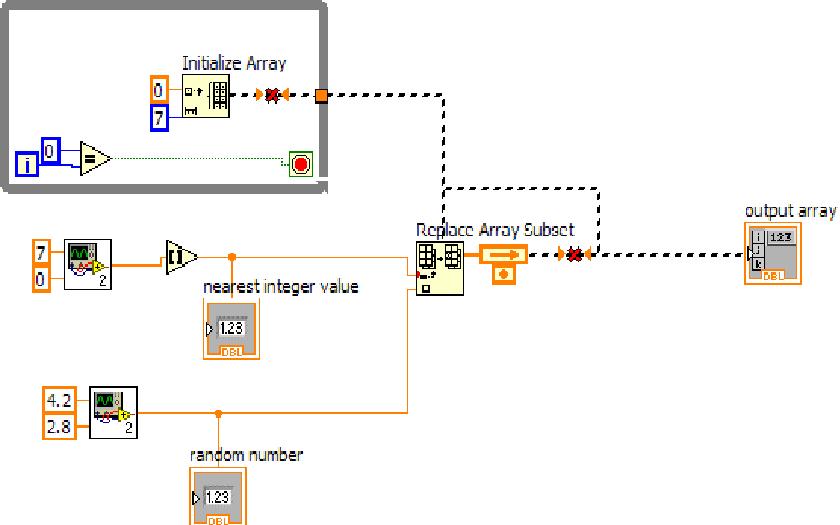
I have a typical problem. I need to store values in a table 1 d with 7 elements. I want to start with a set zero array of items. I then start sending values and indices one by one so that the value is inserted in the table and is stored. My problem is when I start with a zero table, what happens is every time I have send a value that it replaces a zero to the correct index, but does not store this value for the next iteration as the zero table defines the table to zero once again. Changes as well as an item in the table all the time. I won't like that. Once started, I want all my values stored in the corresponding index, unless until a value with the same index overrides. Here is my attempt in jpg format. I tried to insert a table of zero which takes place once in a while loop and then connect the spare in feedback mode Board so that the insertion of elements Dummies happens only once. But I am not able to do. Please help me view inthi
Your image shows that you cannot have a 'next iteration"because there is no point in loop around the code of the replacement array element and the while loop around the table to initialize is useless. You are not clicking on the button "Continuous run" are you? Do not!
Here's a basic example. You can learn a few basics of LabVIEW by taking some of the tutorials.

-
Were they just a passing fad? I have stopped using years ago because I heard they had performance problems. But I've also heard that they were not fully implemented properly and NEITHER would remedy.
-
feedback for sequences in LV8.2.1 nodes?
Hello
I used nodes of feedback with stacked sequences several times in the recent past, but these days, it doesn't seem to work... I reinstalled some LV components lately, and I wonder if I've demoted from unintentionaly parts of LabView. There's feedback auto nodes into sequences included in LV8.2.1?
Basically, I need to transfer data of 0 and 1 sequence in a stacked sequence sequence. I used to connect simply and a feedback node appears automatically. Now it gives me just a cut wire and complaints about the creation of a cycle. I tried to add the node of feedback manually, but it does not accept it. The 'Help' explains the methods exactly as I'd expect, but it just doesn't work...
In addition, my older screw with nodes of comments always compile correctly (no error).
No idea what can happen? I guess I can use a sequence of flat, but I was really intending to use a sequence stacked to keep the block diagram small and sleek.
Thank you
Benoit
Sequence inhabitants allows you to transfer data from one image to the other. I don't understand how you can use a feedback node. Need your VI or a picture.
PS Sequence structures of any kind are rarely necessary and the use of a stacked sequence is considered by many to be very bad style. You should consider how to remove the structure of sequence all together and use data streams.
-
Sub - VI with nodes of feedback used more than once inside a While loop
All,
I have a Subvi is a set of operations and using 3 feedback nodes. I use this Subvi inside a loop While 4 times in total. I noticed all instances used to share the same result in each node for your comments, but I would like to have an individual result of each of them. Is there an easy way to work around this problem? I find ways to avoid this: a) create a different vi for each time the Subvi has been used. (b) use global variables instead of feedback nodes. Is there an easier way to get around this problem?
Example
 Please note that the two sub - VI are the same) If on my first Subvi I calculate a maximum value and get 1.29 (then goes to the crux of feedback) on my second slot - VI 1.01 my feedback to the Subvi second node records still get the maximum value or 1.29. (and I want it to be 1.01!)
Hope, that it is not too complicated, I was scratching my head with that for a while, can't find the "easy" button Thanks in advance.
-Pop
IM using 9.0.
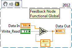
It would be useful to join the code. Anyway, I'm not sure how several knots of comments are supposed to work so I will defer to others to answer that. As far as being able to use separate or instances values if you are using a Subvi, you could mark it as reentrant. In this way, each call to it will behave as it were a copy of the VI and it will have its own memory space. This should include the feedback node. You end up with a single slot - VI and in reality a single node of feedback. If you need pass data between calls that simply data through wire. You can also use a motor of Action to store and retrieve values. An EA is MUCH better than a global variable.
-
Branch 2 ports introduced "node of Feedback.
Hello
When connecting 2 ports LabVIEW requires Feedback node.
What could be a reason for this?
Thank you.
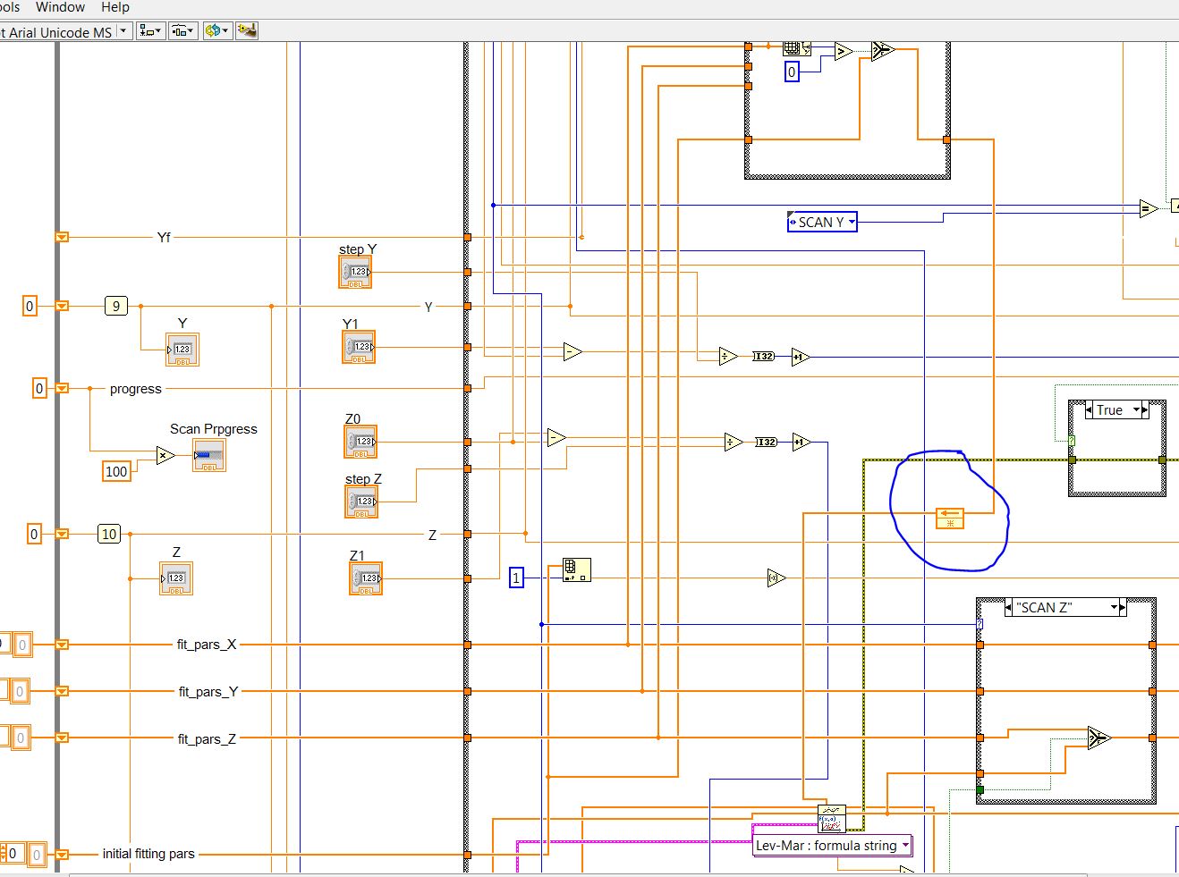
PS Code is huge, so I put just a fragment
-
Anyway to save the data in a loop without using shift register or feedback loop
Hi all
I've been thinking, is it possible to save data in a loop to the next iteration without the use of a shift register or a feedback loop?
I need the possibility to reload the data within a loop from a file of lvm, but I want to use the same data until I have load some new.
The reason why I don't want use the node registry or feedback shift is due to speed, although I don't know if the registry change
in fact moves all the data of one register to another, or if it is stopped until a change data occur.
I want to reuse data medium and large (6 measure of strength, pressure 2, 1 flow channels) of about 10 s data in each file with samplingsrate of 2 kHz...
In my testing program, I have several CPU demanding computations and 3D graphics, so I want just to minimize the CPU loading as much as I can for each part of the
software...
I am enclosing a small VI to explain what I mean.
I have now, I shouldn't use the express VI and I'll change that as well - it's just a proof of concept!
Hope you guys can help me better understand this shift register...
Thank you!
-Tommy
If the speed is the name of the game, go with the flow (data) and stick to a shift of registers or feedback node. No data is moved, their job is to do pretty much exactly what you describe. Any other solution, control/locals/globals will imply a copy of the data, and then you will have problems with speed.
-
Node FB: Initialize on first convocation
Hi all
Don't know why, but my Initialize on First Call option on some of my comments nodes is disabled. Can you tell me why? Thank you!
Yik
The feedback node can overall initiallized unless wire you a value to initialize the Terminal. When wire you the initial value of the other options are enabled.
Some help is a bit lacking but if you select nodes of comments property page is explained here
-
Hi all
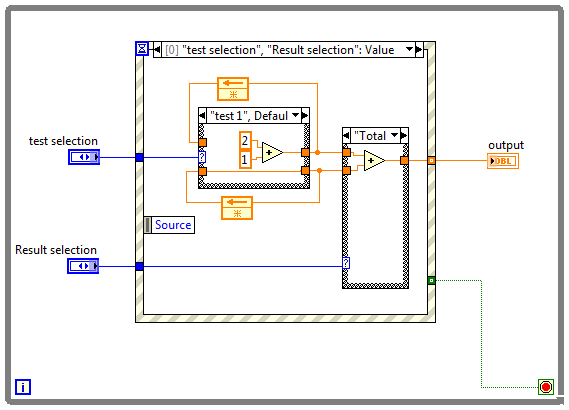
I have a question on how to account for multiple results. Here is my configuration:
- I have 2 test
- I would like to report the result of the test 1, test 2 and total of test1 + test2
Please see my attached VI
Thanks in advance,
That would be because you need to start training.
Introduction to LabVIEW for 3 hours
Introduction to LabVIEW for 6 hours
Paced self-study for students
Self Paced Training beginner to advanced, required SSP
LabVIEW training WikiThe fundamental problem is that there is no element of memory (Feedback node or shift register) to store the data of several [the course
If you select 'Test 1' default data for 'Test 2' (a ZERO) came out of the first structure of matter. Conversely if you select 'Test 2 '.
A pair of nodes of feedback wired through the structure of the case are required to "Remember" the last value of test.
Somethimg like this works much better
home in 2011
-
I have problems with of the Subvi after the use of customized device model
I used to start my machine personalized customized device model and I got success in the deployment until I started to do more complicated the Subvi. I am currently trying to convert low FPGA and high ticks to the duty cycle, but for some reason when I add it to the RT VI "Data read of HW" driver, it seems to cause a downtime... ideas? Is a circuit agree? I have added a time delay but I am still having problems. It is a device online, so I'm suspicious of it hogging resources, but am not sure.
Attached images are meant to be read like this:
1. the case of the RT pilot ReadDataFromHW
2. it's the Subvi calling ToDutyCycle SIMStimPWMSubVI
3 ShiftRegister.PNG is inside the Subvi.
As a robotician I celebrate early and often (usually by a failure or two...), but it seems that the answer was to transform fundamentally the While loop for a loop with a count of 1 and then remove the additional elements to ensure that each shift register has that one and then right click on the shift registers and convert at the Feedback node...
I was able to deploy to VeriStand as a custom device and it runs and calculates the factor of use with no problems. WOOHOO! Where - what is celebrate button! -
Retaining the last value without a while loop
Hello
I'm using LabVIEW 2013. My VI is attached. I'll send in a 'Curr. Random random numbers TestPlan Row"time. I'm eager to keep his last number, whenever this VI is not called and then reset the value to its new value whenever the VI is called again and a new number has been sent. Also attached is a screenshot at the VI.
Please note that I can't use a WHILE loop, so it must keep its value in a different way...
Thanks in advance for any help!
SM
Maybe a feedback node?
-
niHSDIO dynamic generation and Acquisition using LV configure Trigger VI
Hello!
My experience is limited within the environment of digital programming; Nevertheless, I have worked on this problem for a few days and would appreciate some comments if possible.
I am trying simply to generate and acquire a duty cycle of 50% of 8 MHz TTL pulse train on a PIN DIO of the PCI-6541 and acquire back from the signal on another axis of DIO. I have a connector corresponding to the embedded 6541 VHDCI connector which of course the generation and acquisition DIO welded pins to provide a loopback effect.
In short, I use the niHSDIO configure Trigger VI (instance--> start Trig: SW), niHSDIO send software Edge Trigger VI and write Named Waveform VI (instance--> data: 1 D U32) in the generation section. For the section of the acquisition, in short, I use the VI of waveform Fetch niHSDIO (instance--> single record: WDT).
I see results in the waveform acquired showing the generated and acquired digital TTL pulse on the respective DIO pins train, but I can't seem to get my 8 MHz frequency requirement. In addition, the lower part of the assignment of pin DIO, more frequency. Unfortunately, due to the configuration system required, I have confined myself to pin 12 DIO for the generation of digital pulses. Even with a 50 MHz clock frequency, I'm ~ 6 kHz of frequency acquired max. I looked at changing the parameters of the wave form VI named write, but it is not possible because the VI call a library function node. I also tried to generate a waveform of 8 MHz through a VI of generator of digital model, but I do not believe, you can trigger on generated waveforms? It seems that you must generate data using a simple loop to as a counter and sending the result to the waveform VI named write. Are there other ways I can simply generate and acquire a digital signal of TTL of 8 MHz (no external connection)?
In any case, any kind of feedback would be greatly appreciated.
Thanks in advance for your time.
Dan
Dan,
Sorry about the nomenclature. I usually use 0 x or 0 b for indication of radix, it is not necessarily a kind of standard, just what I used in my old days of the Assembly.
Looks like you have a knowledge about the data. Basically the material is just save in DRAM an array of words of 32 bits, with each bit corresponds to a data channel and each element being generated to the sampling clock rate you enter to your vi. Everything else is just easy data manipulation or usage. The interleaving method is just as I like to create a toggle model. You can easily do a loop with an inverter and feedback node or use on the construction in screws to signal generation. In addition, you can use the software digital waveform editor or control panel test to generate the county or toggle modes.
Give us an update when you enter the laboratory and let us know if you encounter any other disorder.

Maybe you are looking for
-
Since Firefox 36.0 shows grey exclamation on https connection
Hello before FF 36.0 everything worked well. Since FF 36.0 Firefox shows my connection with a grey exclamation point. IE, Chrome 40.0.2214.115 11 m also show good SSL/TLS connection. There are no images or anything else without charge https. It is a
-
Impossible to change the video quality YouTube app when using cellular data?
Basically, when I'm on my data (AT & T) and decided to watch a video automatically plays it at 1080 but it burns my fast data. I tried to change through the video, these three points there and says unavailable. I go into settings YouTube app and I do
-
I have always used Firefox. Today, it was impossible to connect. Restarted my computer AND the modem/router. Another computer on the network CAN focus on Firefox. I can devote himself to explore. When I try Firefox window comes up with "unable to con
-
Need help with an expiration date
I have as of today on my spreadsheet, need help to make a column of expiry date which will go to the Red 20 days before expiry. Not to find the formula, please help? Thank you.
-
Our client has a map of IO 6527 works through an SCB100 interface. One of the outputs is connected to a door lock solenoid. Following the instructions 3:3, HiZ Port / Port 3:3, LoZ in its sequence, we measure the voltage to the solenoid 0 and despite