calibrate the values of 12-bit ADC
I'd like to understand how to convert integer values of a 12-bit ADC in tensions. I use a box NI USB-6008 in differential input mode. It is 12 bits of resolution in differential mode. I use a simple VI to collect 100 samples of the differential analog input voltage 0 (AI0). When I connect AI0 + and -AI0, the tension between them must be zero. When I traced the number returned by the routine of the CQI data, I see-32768 values most of the time over a few jumps to + 32752. When to convert format I16 U16 format numbers. I see values ot + 32 768 for the most part, as well as a few jumps to + 32752.See attached shot of front block diagram of the display panel.
Looks like Labview add 4 zeros at the end of the right hand of the binary number 12 bit returned by CDA. Is there a simple way to make ADC return numbers like 0, + 1, -1, when the voltage is about zero? I could do the following:
1 convert the values returned by the ADC since I16 to U16.
2 divide by 16.
3 subtract 2048.
I teach students about the basics of analog digital conversion, and I don't want to have to explain this clumsy scheme, if I can avoid it.
Thank you.
Bill
Hi Bill,
Looks like you've discovered the complement representation two that LabVIEW uses to represent signed integers. Not adjusted data are drawn directly on the hardware registers and are represented as they are on the unit.
If you want to convert the values, you can convert as you have indicated. You can also take the opportunity to explain the complement to two of them if it's as part of your course, or you can just put the arithmetic in a VI if you want to hide.
If you look at the unsigned values, you could also explain to them that it is in the voltage range, the value is.
For example, 16-bit unsigned gives a range of 0-65535. If you have selected the voltage range is-10 to + 10 v. If you have 0V, so you should expect a reading around 32768.
Here's the wikipedia article on the complement of two for reference: http://en.wikipedia.org/wiki/Two's_complement
Tags: NI Software
Similar Questions
-
How Photoshop converts the RGB 16-bit values to 15-bit and 8-bit?
Can someone please help me understand what rounding of diet or another algorithm is used when Photoshop reduced a 16-bit color 8-bit?
For example, the two colors (was and B) are the colours of 16-bit swatch taken directly from a file of the ACO:
A16 = (61603, 60948, 58982)
B16 = (58326, 57015, 52428)
Photoshop displays the values of "16-bit" (acutally 15 bits) as well:
A15 = (30802, 30474, 29491)
B15 = (29163, 28508, 26214)
It seems that the 15-bit values are the result of the division by two and rounded to the nearest integer.
With 8-bit, it's another story although:
A8 = (240, 237, 229)
B8 = (222, 227, 204)
Now, if we divide the 16-bit value by 256, the following:
A8_float = (240.6, 238,1, 230,4)
B8_float = (227,8, 222,7, 204.8)
It's a similar story during the allocation of the 15 by 128 bit values. No system rounding or truncation will get the same answers as Photoshop for 8 bit I see. What I can't work, it's how Photoshop calculates these figures. It's the division of integers, floating point division with rounding or truncation? I'm puzzled. Help, please.
-> range 32768-65535: (32768 * x + 32767) / 65535
Not quite dividing by 2, otherwise you miss the white point.
32768-> 255 range: (255 * x + 16384) / 32768
With the exception of dithering, it is all simple mathematics.
-
I have some 24 and 32-bit PNG. On the bridge Panel, I don't see the value of bit depth.
I see the value of bit depth (8-16-32) for the PSD but when I generate a .png32 that this value does not appear on the Bridge Panel file properties; I check on Panel detail of Windows image viewer and it says 32 bit. Thanks for your help!
Hi iolnation,
No, Bridge does not show the depth of bits for PNG files. You may apply for a feature on the link below, telling them why it is important for you to see the depth of bit for PNG in Bridge. I'm all for anything that will affect better PNG.
-
DAQmx read - the values on the scale or not? Binary conversion.
Hey everybody,
I had a question regarding making the scale and the release of Renault. I use LabVIEW 2009 SP1, with a pilot DAQmx 9.0.2 and a X-Series card. I'm reading the data my DAQ and store it in a binary file.
How is the acquisition of data read samples, in General? that is if I select NSamp NChan I16 2D Analog on my DAQmx Read, what kind of values can I expect if I was at the exit of the probe data? (Suppose I have readings in mV values and my overall fork's 04:55 V.) When he wrote in the binary file, what happens, what can I expect to see in terms of values - or maybe just descriptively?
Overall, a little insight would be very helpful. I tried to troubleshoot asymmetric readings I received, so this will help me immensely.
Thank you.
Hi Matt87,
Reading data as I16 will return the result adjusted, not calibrated for 16-bit ADC.
If you want to write your own binaries, you'll want to include scaling of device - for series X, coefficients a 3rd order polynomial.
Here are two examples that show how write to a binary file and read the data back. In this example, scaling coefficients are stored in the file header:
Continuous gain and voltage drop (binary) chart
Graph of the acquired binary data
That said, I would recommend that you look in the record feature integrated TDMS introduced in DAQmx 9.0. The result is a file appropriate binary .tdms which is a standard format that can be opened in LabVIEW or in several other programs with the plugin. See the following examples for how to use the function:
Streaming data and log to the PDM file
Continuously to log in a PDM file data
The second example does not force you to read the data in the memory of LabVIEW and use the minimum CPU. The first example allows you to see the data that is acquired.
Best regards
-
Calibrate the compass of the iPhone?
I have a new iPhone OS (iOS 9.3). According to Google Maps, the streets of my neighborhood are perfectly North/South and East/West as close as my eye can detect, both within a few degrees maximum. But the compass in my iPhone shows them being about 15 degrees off the coast of true North or 30 degrees on the magnetic north. The magnetic declination at my location is about 15 degrees, it's consistent, but seems to be about 15 degrees off the coast.
Is it possible to calibrate the compass of the phone? Or a compass of this kind is simply not terribly accurate? Or Google Maps is from afar? (The latter seems unlikely.)
I found the web pages that talk about ball to do a bit of red to move around the screen, but I get only the ball. I tried to quit all applications, including the compass application and then launch the compass application, as suggested on one site, but I don't always get the red ball of calibration.
What I am doing wrong? Or this version of automatic calibration and a little off?
Thank you
Calibration of the compass requires that location Services on. The phone detects if it is calibrated or not and will display the calibration screen if it is not.
Rather than relying on Google Maps, get a real pathfinder compass and check the phone against it. Use the compass to draw a North-South line on the floor with chalk, away from any metal (including the iPhone), then check the iPhone against the line you drew.
-
Set/save the value of the local population of LabView development
Is it possible to set/save value of the inhabitants of Teststand of LabView in the update, so I do not write the value in the variable pane? I can do this to programmatically at runtime with SetProperty, but I want to define them in the update with a VI.
Thank you
I use LabViwe 2012 SP1 32 bit and Teststand 2012 SP1
You have to access the SequenceFile inhabitants and then save it to disk. I have attached a picture and my code.
Kind regards
-
leads the value change in the structure of the event
Hello
Please the the VI attached.
I would like to know what event triggers when the value true or false of the changes led?
In the case of structure above the structure of the event, the values of true or false of the led are changed.
From the change, the analog output for Acquisition Card changes. However, the change event of the value in the structure of the event never fires, I know that I run the Vi with the selected highlight enforcement tool.
Thank you
Venkat Rao
Changing the value in an event structure occurs only if one of the two following situations occurs.
1. the user who modifies the control on front panel. That may not happen since these LEDs are indicators and does not control.
2. the program writes a value of property of the Value indicator/control (signalling) node. Writing to the terminal of the indicator, or the local control variable / indicator not fire the event. Given that you do not use value property (signalling) nodes in your program from this moment, won't happen either.
Note that the value change event is a bit misnamed. The change event is triggered, even if you do not actually change the data. So if your LED is currently worth, and you write a True Boolean value for the Value property node (signalling), the event always fires even if you're not technically change the data.
-
Dear experts OR,.
I have a PCMCIA DAQ6062E card OR makes the ADC and DAC for the collection of data in my lab. However, I'm confused with the bits of resolution posted on the Web page or http://sine.ni.com/nips/cds/view/p/lang/en/nid/11918. On the description on the right of the 6062E map image, it says: "..., 16-bit analog input,..." However, if you click Open the book loads tab below, under the heading "Analog Input", it says: "resolution...". 12-bit". Even for specifications under the "Analog Output" section: 12 bit. Dear Sir or Madam, I think I'm confused. NOR-6062E DAQ has a 12 bit or 16 bit ADC?
Sincerely,
Fuh
Dear Seth,
I thank very you much for the clarification.
Sincerely,
Fuh
-
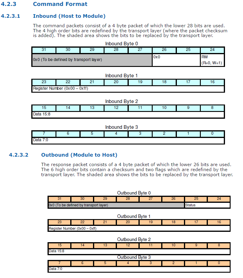
urgent request: how to read the value of a register using VISA read?
Hello world
This is a very urgent investigation. can someone help me please? Thank you very much!!
I wrote a few commands in several registers using VISA write. now, I want to read the value of a different register.
But the bytes returned are just the commands, I wrote before and a few other commands that I don't know what they are for.
This is the format of the command, and I enclose the sheet... I want to read the value of register (0 * 41)
.
Ravens, if you have something more than me, do not so much it at all =)
The command you have posted has several components:
The gray area of the transport layer uses for a checksum
several bits set to 0.
a single bit to define if it's a read/write operation
a byte to identify the register of interests.
two bytes for the data.
With what you have provided, there are only three things we need to worry:
(1) set the R/W bit to 0 to mean we're reading rather than write.
(2) set the second byte 0 x 41 to focus on the register of interests.
(3) with a reading, I can't imagine the last issue of two bytes. They probably ignored. The documentation you provided does nothing to explain this. The most logical thing I can think is that these two bits contain the data, you go to the registry if you set the R/W bit to 1.
There are two parts to this communication. The first part is an entry VISA to send this control unit. It is likely that you will need to complete the message. You will need to know how to do this.
The device must respond with the message that you mentioned in the original post. Crows is right. He's coming back as a string. You can use the subset of string to separate the components defined by the standard. You can use these components to determine if the data is legitimate and then do what you want with the data.
-
Change the values on the axis are in text
Hi all
I'm tracing a few weather data, I took a Web site. A detail that I extract from the Web site is rolling of wind. Extracting value is very good, and I find myself with a value between 0 and 360, which corresponds to a direction. I can trace it on a chart compared to the time I acquired data. One thing I would do is to create a second scale of y and change the numeric values for text labels to describe the meaning, so I N, NNE, DON'T, etc. as well as the value of the azimuth in degrees. I cannot find a way to add text to the second ladder, I missed something or it's a bit complicated to do? I have attached a picture to show what I mean.
If I missed a post on the forum about this, excuse me, please paste the link in a comment below.
Thank you very much
Joe
Pack them salvation.
I cannot find a way to add text to the second ladder, I missed something or it's a bit complicated to do?
No, you didn't miss anything. You cannot display text in the y-axis.
But you can hide the axis values there and place a string indicator in the place!
-
Send the name and the value of the control to Subvi
Hi all
I am trying to send the names and values of the controls to a Subvi.
I know that I can check out the name and the value of the control by using a property node, but I was looking for a way to make is easy for the programmer to use.
I think some sort of bundle function, it records the name and the value of the control, but I would like the programmer to be able to connect a random number
controls to the Subvi without having to specify the number of controls Anywhere.
I know there is stuff in labview configuration file, but it seems a bit more complex, so what I want to do.
Also, I know that I can use the OpenG toolkit, but I will not use additional LabVIEW modules, as this VI may run on several different computers.
I hope I made my problem clear enough!
Good day
Concerning
Tommy
What, creating an array of references to the command. On the hand, you will need to fill the table with control references that you want to send to the Subvi. In the Subvi, use a loop For with indexing to get every reference, and then use the nodes property to get the name and value.
-
store the value obtained in the while loop
Hello
I'm data acquisition (1,000 points every 0.1 s) in a while loop. I would like to calculate the average y of the first sample of 1000 points when I click on a Boolean 'calibrate', store that value somewhere (outside the while loop?) so that it can subtract from each new amplitude y. In the vi below, a new average value is calculated in each loop, although I would only use the first.
You don't need to store the value outside the while loop. Keep the offset of the value when calibrate button is pressed and subtract the value with earned value. I modified your find VI the VI attached.
-
a bug with the structure that contains bit fields?
using CVI 8.5. I tried to set up a structure that contains bit fields. Although the structure compiles, I encounter strange behavior when you access individual fields, while the value of the overall structure seems ok. Here is the structure:
typedef struct
{
Union
{
struct
{
unsigned int Flag1: 1;
unsigned int dummy: 3;
unsigned int Flag2: 4;
unsigned int Indicateur3: 4;
unsigned int dummy2: 4;
};
unsigned short;
} flags;
} flagset;When you set the Member 'all' to a value so that one or more indicators, but not all, are false, I still read the individual like real flags, until all flags are set to false.
I missed something? This definition is really legal?
Please find attached a file showing the problem.
The same issue is at stake with or without the ternary operator. It turns out the problem was not specifically with printf, but rather a bug in the compiler that is related to the evaluation of the members of anonymous internal structures. If several internal anonymous struct members are evaluated before the compiler actually do anything with the result - which is the case when passing arguments to a function-, so they will all be evaluates the value that was evaluated last.
A. Mert
National Instruments
-
How can I write the value of floats Unitronics vision230 PLC with modbus Ethernet
How can I write the value of type Float in unitronics PLC Vision230 modbus ethernet (Ethernet Master Query.vi MB) usinsg I read and write register 32 bits, for example, I want to write the value 23.45 2nd Add. MF. And registry MF is the 32-bit registry. I read and write register 32-bit.
Narendra.
Narendra,
Two characters can type cast into a uint16 you VI supports.
To summarize. Take one (4 bytes). Flatten it to a string (4-byte) divided this string into two parts of 2 bytes each. Cast in u16 (16 x 2 = 32-bit).
However, if you really want to follow the IEEE standards then you will need refer this KB. His is not that simple, but seems closer to what you are looking for.
Amit
-
How to calibrate the sensor of gravity on Z3?
My gravity sensor is a bit tilted, but I can't find anything to fix.
There used to be a possibility to do it on some old phones Xperia, but it seems that this feature has been fully subscribed.
Y at - it all posibliliy to calibrate the sensor of system level?
You may need to stop by your local care of Xperia, based on your previous posts
http://talk.sonymobile.com/T5/Xperia-Z3-compact/bounce-back-still-happening/m-p/936387#M7046
Maybe you are looking for
-
Why my Mac under 10.12 only sleeps for 2 seconds?
I installed Mac OS Sierra tonight. Whenever I put it to sleep under the Apple Menu, he sleeps for a second or two and then the screen wakes up again. My system has never done that before Sierra. How should I do?
-
Model of LabVIEW VeriStand 2013 IO question
During a project, that I'm working on, we decided to update our version of NI LabVIEW 2013 and 2013 VeriStand. For this project, we manage a combination of models, the .lvmodel and the .dll (compiled model Simulink). These models are deployed to an R
-
Dual monitor on HP Pavilion p6610f
I would use two monitors on my HP Pavilion p6610f desktop computer. I have two lcd monitors. I buy a vga adapter digital and connected a monitor to the VGA in the back of the computer and plugged the adapter connected to the other lcd screen in th
-
Hello I'm talking to s TDS3054 carried via ethernet and VISA. TCP/IP is configured correctly and the scope is displayed in the browser. However, when using MAX see it and to show the Panel VISA and he will answer to the sets and gets, but when I try
-
Vista installs updates over and over again
My PC keps install the same Microsoft updates over and over again whenever I stopped him?