Capture high speed encoder data
Hello
I have a motion control project where I would record the position data. High speed capture is limited with sampling frequency of 2 kHz. But I have to save a lot more than higher speed.
I read that there is another option that connects to the motion control card (I use a card PCI-7358) and the map of data acquisition using a RTSI cable and channels A and B of the routing of the data acquisition card encoder using the RTSI lines.
I have 6143 and 6280, 7358 PCI DAQ cards and a RTSI cable.
Q1. Which card is better to use? 6143 or 6280?
Q2. When I look at the examples, I have seen that its possible to phase has the traffic and signals of the phase B of an encoder for the RTSI line with Signal Select.vi. But I couldn't find an example on how to read of DAQ card.
Q3. How can I contact the encoder position phase has and band B pulses which is acquired from the DAQ cards?
Concerning
Hi serkanb,
The 6143 has no support for measures of encoder quadrature (although you can run a task of count of edge and use the B signal as a line up/down to get a similar effect). If you are interested, we'll find more information here (the 6143 uses the same SC I ASIC that make the E Series DAQ devices).
It doesn't really matter too much since you have a 6280 that supports quadrature encoder measures (he uses the STC II ASIC). To answer your direct questions:
Q1. The 6280 is better (see above)
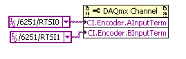
Q2. You need to use a channel DAQmx property node to choose what terminals to use for your task of encoder:
Q3. I would like to start with an example of the expedition:
Help > find examples... > input and output material > DAQmx > counter measures > Position > measurement Position.vi
You insert the property node before starting the task (but after the channel is created).
I hope this helps, if you have any questions do not hesitate to post back!
Best regards
Tags: NI Hardware
Similar Questions
-
By axis high speed capture using UMI-7774
Hello
I want to use capture high speed on each axis of my pci-7344 Controller.
I use UMI-7774 and evrything is correctly connected to the command of servo etc...
I read the manual of the umi-7774, but I see nothing on the capture trigger high-seed.
How do I use the signal high speed capture for axe1?
What are the necessary wiring to the umi-7774 to use this signal?
Page 3-25 in the Manual: "the UMI-7774/7772 has one 15-pin D - SUB connector you use to.
wiring output input trigger and breakpoint. This connector allows access
to trigger four inputs and four outputs of breakpoint. "
is that the breakpoint TRIGGER connector in the Global connectors of the UMI has this signals for each axis?
Thank you
MOR
Mor,
I don't think that it is possible to route multiple signals on the same line of the RTSI, because that would mean that even if a signal is high, other signals take on the same line in a low state. I think that you will use for OR external logic circuits indicates the breakpoint.
Jochen
-
High speed continuous measurement of encoder with sampling frequency of 1 kHz
I am able at all times the position of a linear encoder using a PCI-6602 counter card, and I need to know how to set up so that the counter rotating at high speed, but the data is inserted into the buffer at a frequency of 1 kHz. I am able suddenly to a hydraulic cylinder, and I am not concerned about the event recording to high frequency except to the extent where they throw off the number considerably if the equipment does not run fast enough to detect all the impulses of the encoder.
Now, I think is that the external sample clock signal control (routed internal pulse output counter) time rate whereby the equipment detects the impulses of the encoder and the rate at which it inserts data into the buffer. With a pulse 100 per inch encoder and a sampling frequency of 1 kHz, the extended final position of the cylinder is turned off by +/-0.15 inches, which is unacceptable.
I need calculate a speed of this information, so I prefer not to use software timed sampling to control this (it's more difficult programming for other reasons as well - several asynchronous measures). Any ideas on how to configure the hardware to count faster than the speed at which she inserts counties in the buffer?
OK, you're clearly on the right track here, so I will focus on some details.
1. How do you know that the +/-0.15 "differences are * measurement error rather than * error of movement? Why wouldn't be an accurate measure and a proposal which can vary slightly from the nominal value?
2. I wonder some all electric noise and defects that may produce false edges. The fact that the behavior was better by using a sampling rate limited (200 kHz) in the digital inputs may be that some of these flaws were so short that they were never captured.
I did a ton of work with the Commission to 6602 encoder and I can certainly confirm that count equipment is sensitive to the edges in a few tens of MHz. (I know its 80 MHz for edge counting, but I think I remember that it can be of the order of 20 to 40 MHz to accommodate the time of signal propagation extra of the quadrature decoding circuit).
A small point of clarification. You're talking about the speed at which the meter "works to. The value of count is a register whose value is changed completely by the circuit, * independent * of the sampling frequency. If you enjoy with material-clocked County in memory buffer or interrogation of software without buffer not a bit for circuits that increments / decrements the value of the counter register. (In other words, I am completely convinced that you would get commensurate with position end even if you took only 1 sample software-polled after the end of the move instead of sampling at 1 kHz all the way through.)
So, if the value of the counter is disabled, it is because the circuit detects producers of County of the edges that shouldn't be there. Something you can try is to set up digital debounce filter for input lines of the PFI corresponding to the encoder Source inputs and to the.
-Kevin P.
-
Capture of high speed using flex functions returns null vector
Hello
We have a controller 7350 and UMI-7774 drive a motor step by step through P70530 pilot. We use a single axis, axis 1, which is configured as a stepper motor with your comments and 10000 steps/rev. Our engine performs a profile displacement and during this move, you should read the position of the encoder with about 2000 Hz resolution. I can move the engine using MAX or flex functions, I can also read the encoder using the post MAX, but cannot perform high speed reading.
Issues related to the:
1. How can I configure read it for 2000 Hz at high speed?
Function flex_configure_buffer (boardID, bufferInEnc, axis, NIMC_HS_CAPTURE_READBACK, contMoveBufSize, totalPoints, NIMC_FALSE, requiredInterval, on actualInterval)
Returns the error-70078 (invalid parameter) when I pass a required interval less than 10ms.
2. How can I read data from buffer high speed?
Even when the buffers is configured with the interval of 10 ms, the flex_read_buffer_rtn (boardID, bufferInEnc, rear, out retVector) function returns no data (retVector = null).
Please find attached an example of solution of vs2008 demonstrating the problem.
Hello Stephen,
The problem is now solved, the problem was in the trigger condition.
It seems that the parameter requiredInterval in the function flex_configure_buffer() function call is ignored, because I get to any interval of 0.5 ms data even if the requiredInterval and the actualInterval are two 10ms.
Thanks for your help.
-
Hello
am very new to Labview. I used a data logger high-speed (labview 6i). Files are saved in the binary format. How can I convert files to ascii format or text for post-processing?
Thank you
Hi Valentine,.
I hope you had a good weekend.
I had a go at the conversion of the sample code down to LabVIEW 6, so you won't have problems to open it.
It will be useful.
Steve
-
What is the best way to read data series high speed?
My goal is to read 14 bytes of binary data of an instrument on the serial RS232 (460800 baud) to 2000 Hz. I didn't get a card series high speed again so I am currently using the standard serial port (115200 baud) and reading at 400 Hz I have configure the port series, empty the buffer, and then enter a while loop to read incoming data. I have a visa 14 bytes read by interation seconds 0.0025 (400 Hz). However it seems that the sensor is spewing data faster that labview can read because the bytes are accumilating in the port. After some time the buffer fills and the program fails.
Is there a better way to do it?
Would it not be better to read the larger quantities of data less often, for example as 1400 bytes every 0.25 seconds?
Thank you
Hello
I think it would be good to read several points in a loop, and keep the loop less than 1000 Hz. I found in the past, have something to run faster than about 10ms tends to fall down when windows loses interest in the process. So yes, choose the slower you can get away with reading samples - for example to read every 10ms and read 20 samples every time. You should be able to configure your serial port in order to buffer the samples that I guess.
Also and the issue of windows - if you use a loop "timed" instead of a while loop, so you can force it to an integer value including the ms. You can also assign a dedicated processor and set the priority to 100, which means that it is less likely to elapse and decide to scan your hard drive for viruses or consult your account e-mail or what he does when he's bored with your program. Also it "' tells you if the loop has taken longer that planned to run - you can use this to help iron out bugs etc. - report and/or to the user if you missed a few samples.
http://zone.NI.com/reference/en-XX/help/371361H-01/Glang/timed_loop/
JP
-
acquisition of data high-speed and simultaneous sampling
I'm quite familiar with the coding for NOR-DAQ boards in Labview. What worries me with labview, is that each tick is about milliseconds. I intend to retrieve the data simultaneously from 32 channels at 2 MS/s/chan using SMU 6368 s. Wouldn't not possible to enter data, on average 20 to 50 samples to get a unique value, perform simple algebraic manipulations on it and send it to the PC / software to approximately tens of kHz? We already have labview code to perform similar tasks, but it is quite slow and limiting the rate of experience. I said that Simulink is slightly better than Labview in this regard, but suffers a poor user interface and that if something C/C++ offers the ability to perform at high speeds with the same cards OR data acquisition. Could someone advise me please on this issue?
You can use your PC! You can use a PCI/PCI-e card as the interface to your computer and it should work perfectly. Take a look at these pages (http://sine.ni.com/nips/cds/view/p/lang/en/nid/10389) for more information.
-
How I choose the USB-6251 (full speed or high speed) data transfer rate?
Hi, this is bose, FAE Samsung in Korea.
I saw the USB-6251 specifications that it transfer data at high speed or full speed.
How can I select speed mode?
It depends on computer?
Thank you.
Fairly certain, it is totally dependent on the USB hub.
-
Treatment of LabVIEW data and high speed data acquisition C
Hi all
I am designing a data acquition VI high speed of 3 cards acquition of data at the maximum speed. Data cards are PCI 2517 Measurement Computing. The sampling frequency for each card is 1 M samples/second, if the total sample of M 3/second of three cards. Problem is the LabVIEW drivers and the screws provided by the provider works very well just for a single card at maximum speed, but does not support multiple cards at maximum speed. Their technical engineer advised me to write code in c#, C++ or VB.NET for this data acquition high speed. If I use C forever, I would like to use LabVIEW for processing of the acquired data to data acquisition. I came across a few examples that suggest the creation of dll C code and then calling it a LabVIEW. But those who have programs simple and none of them speak in C data acquisition. My questions are,
1. is it possible to call a C data acquisition program high speed of labview and not work in any kind of present of buffer overflow?
2 would it not simple best to use labwindows CVI?
3. is there another alternative solution that I'm missing?
I'll appreciate all the entries.
Thank you!
Nilesh-
It's pretty easy. Arguments for CINrun must match wiring. You can wire your CIN function block and say LabView to generate the C interface code to begin.
Here's my pairs for the ASIO audio project.
All the best,
Terry
-
If you use up your data at high speed can still download apps?
* O.T. > account Microsoft Family
If you use up your data at high speed can still download apps?
You can, just slower (whatever the speed your Internet company service provider provides).
-
LabVIEW 8.5
Hi all. I have never written LV or any other code to make streaming broadband but I have to now. I did a lot of 2 and 3-way low speed data acq but never down. I could use a little guidance as to how it works.
First of all - what I have to measure. I am able engine valve motion, in real time on a test apparatus part motor engine. I enjoy movement to a slow control RPM can accelerate to maximum speed while taking data. The scan will take 5 to 8 seconds.
2nd - I need to watch. I need to look at the position of the valve for 1 round, taken in 720 points, at low speed and compare it to track even the test RPM. I have to select test RPM after the data are obtained and overlay lo & Hi plots, a control and a test track at the same time. All the analyses to be performed after data collection, not in real time. Sampling of the range starts at around 12 k samples/s and a ramp at 66 k samples/s up to 8 seconds, which will generate up to 312 000 points by scanning.
3rd - I. High speed laser sensor position, more than adequate sampling rate. Rotary encoder, 720 cards data acq pulses/Rev. and chassis conditioner GIS with inputs / outputs. Boards are 6143-PCI and PXI - 6071e. 6143 Board is connected to the encoder and entered trigger. Output laser is 0 - 10v, so I have to use the jury 6071e for analog position signal.
Now, my questions. I know that I can stream to get a high rate, but for analysis, I need to bite these data into pieces of 720 points and they relate to a registered PLAN. It can be analysed by discrete steps, say about 50 or 100 rpm. How to handle a stream from a writing Board and "stamp" with RPM taken of an encoder on a second table? I'm looking for some basic procedure here that will give the data for me in a way that I can actually use rather than a dump of 312 000 point that would take days to analyze without a few things. I calibrate the data after the fact and analyze in a separate program, so I just need voltage data flow. But I need to start at the pulse of Z and take a reading every pulse.
Thoughts?
I had LV 2012 running when I responded to your post above.
I called LV 8.5 and put together this small VI. It generates random numbers to approximately 66000 per second and runs for about 8 seconds. It requires approximately 17 MB. The screen requires a copy (I think) which roughly doubles the size of the data in memory.
Reduce the wait to 1 ms and it runs in about 1 second. It takes a zero waiting ms 76 ms. Then save the data in a shift register or another form of memory will not be a bottleneck.
Lynn
-
Problems initializing digitizer card high speed
I recently built a new computer for data acquisition. I had all the questions according to a program for the acquisition of data for a digitizer high speed written in LabWindows 8.5 and it works successfully with LabWindows 9.0 on the new machine. The only problem I encountered was name the digitizer card high speed max the appropriate name of the resource planned by the data acquisition program. Everything went very well for 4 days. Today, I try to run the same program and cannot enforce. Debug code indicates that the device fails to initialize when niScope_init() is called.
In MAX passes card scanner that can call a test and I have test panels and see an input signal. I checked the name of the device to ensure that it matches the named resource that provides the program. I also reset the device to the MAX and then tried to run the program. None of these attempts succeeded.
I can't really find anything that changed between the last time I ran the program and today. Everybody to face this problem in the past, and is at - it solution or a proposed additional troubleshooting?
This problem has been resolved by reinstalling the drivers for our digitizer high speed. I have still no idea why after four days, something happened to the original driver installation.
-
NEITHER 9213 changing high resolution at high speed. Screenshots included.
Hello
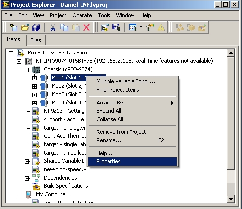
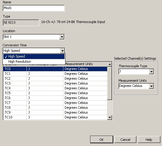
I have a card 9213 in a CRIO-9074. My sampling rate is exactly 1 s/s, which means that it is running in mode high resolution. However when I go in the project window and change it to high speed (as indicated below)...
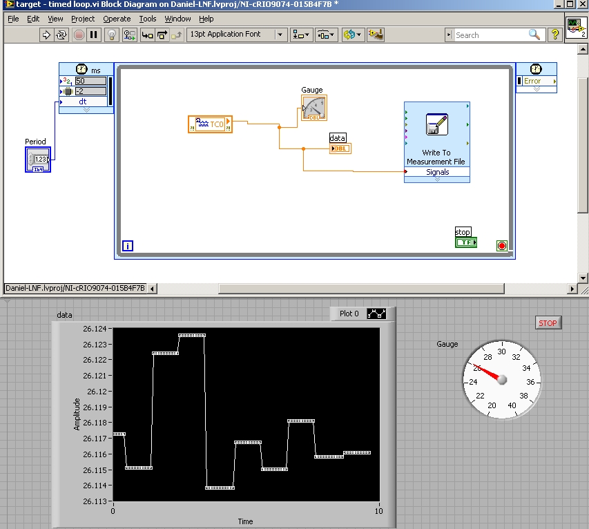
nothing happens. Remainders of 1 s sampling rate / s. below you can see my labview vi, which is a timed loop. The period can be changed in the loop is only how many samples I trace on the graph. And as you can see on the graph to 100ms graphic flatlines as the 9213 is not updated of its value.
Below you can see the record of the following data and it shows that the sample time is exactly 1 s/s.
So, how can I actually get my 9213 OR change of 1 s/s mode high resolution at the 75 s/s, that it is rated for mode high speed. For this initial Setup, I use only 1 thermocouple, but once I get the included sample rate I'll add more. It should also be noted that I rebooted the computer and the Committee for the acquisition of data several times.
Thank you.
I noticed that in your project beside the cRIO, he says "in time real features not available." According to another thread, I found, it was because the module time real wan not properly installed:
http://forums.NI.com/T5/FieldPoint-family/real-time-features-not-available/m-p/954231
Also, when I recreate your project settings, if I right click on the 9213 module I the ability to "Deploy" or "deploy all. Deployment is expected to update the settings.
-
Problems with mathematics at high speed on FPGA
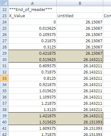
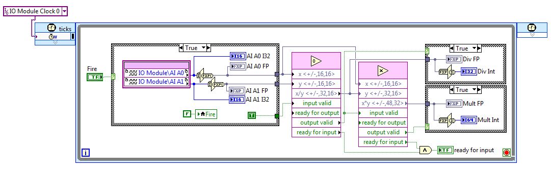
I'm new on fixed-point numbers and math at high speed on the FPGA. I use the 7962 with 5751 adaptation module. I am writing a few simple codes to convince me that I understand what I do before writing code more complex. I wrote a simple code to divide two numbers and then multiply the result with one of the original numbers. The block diagram is shown below.
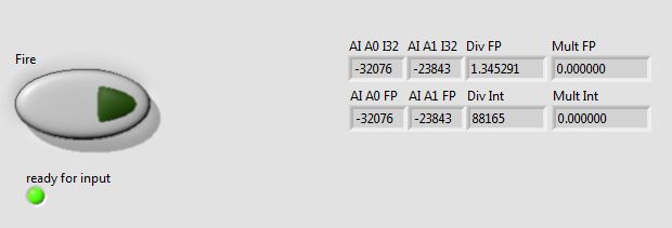
Looks like that the fracture is not working properly. But the multiplication always gives zero, and I can't understand why. A typical result of the façade is illustrated below.
If I remove the divide, the multiplication seems to work fine. Any idea on what I'm doing wrong would be greatly appreciated.
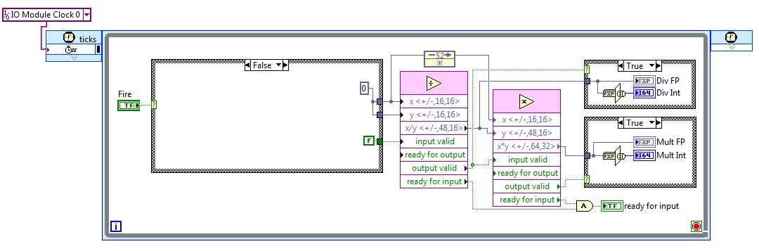
After more than a day of scratching my head, I realized that one of the entrances to the multiply function is always zero, because it is read 52 cycles later (i.e. when the structure case is false). To resolve this issue, I added a node back feed, so that the data is made in advance and are available to the function to multiply once the function of the line ends. I have attached a picture for those interested / with similar problems.
-
Working with USB high speed Interface Modul 2.7 in LabVIEW
Hello
is there an example works with a USB high speed Interface Modul 2.7 in LabVIEW?
The EGG is a "Cypress CY7C68013A-56PVXC»
Thank you
Best regards, patrick
Hi patrick,
I searched on google for the module. The manufacturer is Braintechnology.
If you need a LabVIEW driver ask them please, maybe it's that they can provide you with a.Braintechnology offers a DLL - USB. With a little work, you can include this dll in your LabVIEW project (call library function node).
The following documents explain how to:
Integration of external Code with the Shared Library Import Wizard (requires a corresponding header dll)
http://zone.NI.com/DevZone/CDA/tut/p/ID/2818Writing Win32 dynamic link (dll) libraries and qualifying of LabVIEW
http://zone.NI.com/DevZone/CDA/tut/p/ID/4877Example: Passing a variety of Data Types in the DLL for LabVIEW
http://zone.NI.com/DevZone/CDA/EPD/p/ID/1288Kind regards
N. Ralf
NIG.
Maybe you are looking for
-
How can I use - openURL remote without having to open a new tab?
I have a kiosk based on the web that I built very long time (before tabbed browsing) that uses periodic calls to: Firefox-remote "openURL (http://start.csail.mit.edu/mit-museum)' to reset the kiosk to the homepage (the function depends on the web fre
-
Suggestion for bookmarking easier
Now, you can make bookmarks in any by clicking Favorites - add a bookmark, then you will need to choose a location for the bookmark, or You can rightclick a bookmark (on the bar in the drop-down list or bookmarks bookmark) and select Add bookmark, af
-
I can access Windows Live from my macbook, but when I try to go in my hotmail Inbox I get a sorry, there is a problem with hotmail right now. I CAN access my hotmail to my IMac account. What is happening that I can't access my account hotmail to my
-
Is there anyway to change the Xp pro from Spanish language to English 100%?
Basically I have a Spanish version of Xp installed on my computer. I want to update so that everything is in English of the screen starting and all that comes after. Instead of say Bienvenido when it starts, I want to say welcome I want to say change
-
Impossible to change the screen resolution
The larger screen, to adapt to a game, but now I can't cancel it, because when I go to the screen resolution to make it hiighr, I can't scroll down to apply it, and there is nowhere on the screen I can reduce its size.