Capture the signal micro PC line
I am aware of LabVIEW Sound screws and I used them often. My question is that if I have a line in signal plugged into the microphone port, how can I capture. There is no mic involved, just a line of sinusoidal signal.
Thanks for the help,
You will use the same vi as if it were a microphone.
The limits will be in your sound card capabilities to scan the sinusoidal signal and not the limits of LabVIEW in itself.
Tags: NI Software
Similar Questions
-
Not able to capture the signal in the TDS 3032 B
I use the 3032B TDS oscilloscope. I am not able to capture the signal in the oscilloscope or the LabVIEW. I use the RS 232 communication between the oscilloscope and the system. Y at - it none of the oscilloscope settings. Please help me.
Kind regards
Renaux
I tried and got he was able to capture the wave and also display in the program.

-
How to capture the signals using the macro excel 2007 with lecroy activedso object
Hello everyone...
I hope you could help me.
SURVEY:
I have a macro code, but there is no output from the image displayed in the specified activedso object after successfully connected to the specified IP address.
I think that there is a problem by specifying the activedso object.
THE MACRO CODE:
Private Sub CommandButton1_Click()
Dim o As Object
As Boolean Dim successSet o = CreateObject ("LeCroy.ActiveDSOCtrl.1")
ipadd = ActiveSheet.Range ("B1"). Value ' in a specific cell ip address valueWith ActiveSheet.OLEObjects ("ActiveDSO1")
success = o.MakeConnection ("IP:" & ipadd) ' if the true value, capture the current image of the osci waveform digital lecroy and displayed in the object activedso
If (success = False) then
MsgBox "not found DSO! Address can be a problem... '& o.ErrorString '.
GoTo 999
End If
Ends with999 set o = Nothing
End Sub
If there are questions or disputes my inquiry please do not hesitate to answer.
Hello Jeff,.
It is also a pleasure to meet you!
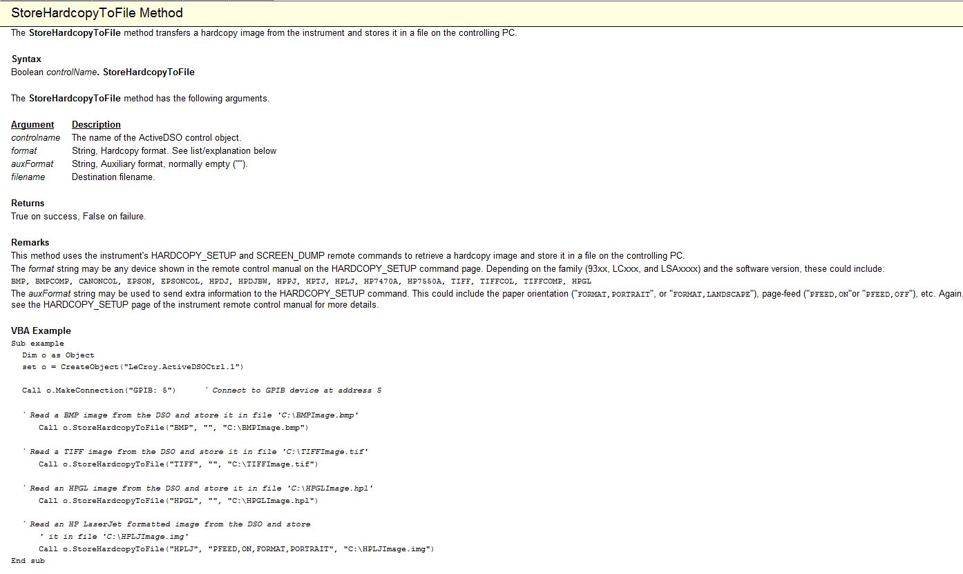
There is a method "StoreHardcopyToFile", that you can use to get a picture and save it on your PC.
Here is a picture from the help file ActiveDSO showing the method with a VBA example to use.
Let me know if you have any challenges.
Kind regards
Leonard Brown
Technical sales engineer
Teledyne LeCroy
1-800-553-2769 -
How to capture the event adding table line
Hello
I need to capture the event of the button Add new rank in the region of the table.
Because I need to make a treatment for this action.
How can I capture this event in processFormRequest()?
pointers?Use the following code
If (ADD_ROWS_EVENT.equals (pageContext.getParameter (EVENT_PARAM))) {}
custom code
}Prasanna-
-
How do I capture the output of voltage full bridge with Signal Express NI9219
Hello. I'm trying to do and calibrate a load cell with the installation of full-bridge strain gage. I use a NI9219 module with a cDAQ chassis. Is it possible to capture the actual output voltage? Signal Express gives me a value of strain, but I really need to know the output voltage. Where to look. I need only two channels for full-bridge. I think that could connect the wires to the two remaining channels and read the output voltage of the strain gauges which would be connected as a tension of the 9219 entry, but I think that Signal Express could give me the voltage and output voltage directly. Any input would be appreciated. Thank you! P.S. I only use this equipment on occasion and am not the more familiar with it, so keep things simple for me. Thanks again.
Hi jgh@AET,
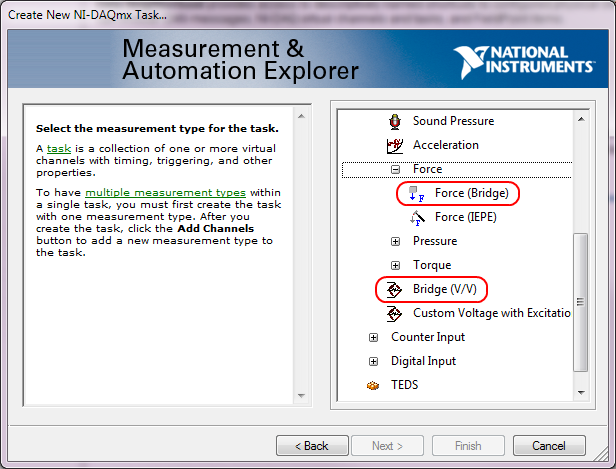
The NI 9219 measures the ratio of voltage full bridge in hardware sensors, allowing any variation of the voltage to cancel. You won't be able to measure the output voltage of the sensor regardless of the voltage without additional channels, but you can measure the ratio of raw tension using the type of Bridge (V/V) . You can also use the type of measure of Force (bridge) measurement of load cell with engineering units (N, lb, kgf, no strain).
This screenshot shows where the two Bridge (V/V) and Force (bridge) can be selected in the DAQ Assistant:
These types of measurement were added sometimes around DAQmx 9.1, so if you have an older version of NOR-DAQmx, your DAQ Assistant maybe not them. The latest version is currently 9.4 of NOR-DAQmx. Front of NOR-DAQmx 9.1, the approach to recommend to measure the load cells was to use the custom with Excitation voltage type and a custom scale. However, Tension Custom excitedly can't Bridge of calibration in the DAQ Assistant.
Brad
-
It is possible to capture the lines of delete with the CHECK feature operations?
10.2 using triggers I can connect the deleted lines, but is it possible to capture the lines of delete with the CHECK feature operations?
Thank you.You can find Fine grain auditing and capture strategy audit records (for example, access to a column), and also capture the SQL text.
But that still won't 'copy' on all lines accessed by the user who runs the verified order (for example a DELETION).
If you want to "save a copy" of the row that has been deleted by a user, you would still have to write your own trigger ON DELETE. -
Capture AbstractActionItem SIGNAL to slip into the menu drop-down
Hello
So I need to do anything when I press the ActionItem in slide it towards the bottom of the context menu on BB10.
I created the shot on the menu drop-down
    Menu *menu = Menu::create();
    Image infoIcon = Image(QUrl("asset:///images/info"));
    menu->addAction(ActionItem::create().title("Info").image(infoIcon));
    menu->setObjectName("infoItem");
Looked at the docs. AbstractActionItem
https://developer.BlackBerry.com/Cascades/reference/bb__cascades__abstractactionitem.html the action point emits a triggered() Signal.
Then ran info a bunch of question that did not help.
- Looked QTDocs
- Looked at the signals & Slots section of BB stunts Docs
in my App.hpp file I added
public:
   void debugText();
I tried to connect the menu by using the following code:
connect(menu->objectName(), SIGNAL(triggered()), this, SLOT(debugText()));
It does not work, and I spent 2 hours trying to figure why not.
How do you connect in fact these things?
Thank you!Hello
trigger signal is attached to ActionItem itself and not Menu object.
And don't forget the Q_SLOT macro.
class xxx : virtual QObject {
  Q_OBJECT

public:
  Q_SLOT void debugText(void);
};

Menu *menu = Menu::create();
Image infoIcon = Image(QUrl("asset:///images/info"));

ActionItem *mItem = ActionItem::create().title("Info").image(infoIcon)

menu->addAction(mItem);
menu->setObjectName("infoItem");

connect(mItem, SIGNAL(triggered()), this, SLOT(debugText()));
Nicklas
-
Have signal via Qosmio player, but failed to retrieve the signal on WMC
I have to be halfway there, but after connecting my NTL cable box to the Qosmio and who received advice to get my signal through the reader and the F2 key, I can't then the signal in Windows Media Center.
As I am only interested in recording TV shows, I really need find a signal through WMC. Please can someone help I think I ever recover calls promised from the technical support line. Oh, I followed all the instructions, but the analysis through Windows Media Center does not give any signal.
ADMISI,
Exactly how do you connect your NTL cable box to your Qosmio?
Willow
-
ConfigFree does not show the intensity of the signal
ConfigFree works properly - except that the Wifi strength is displayed at the highest level for all sources, regardless of how effective. (as it is deducted from the source location and the signal strength indicated by the utility windows)
I.e. all access points are on the inner ring.I am running Vista on a Portege M400 with Configfree version 7.0.0.24 and Intel 3945abg driver 11.1.0.86. I got the Intel proset utility loaded, but they would not show the signal strength at all. So I unloaded it.
I tried rolling back the drivers for the driver Wifi and Configfree with no change in behavior.
Any suggestions at all would be welcome.
Rod Laird Australia
Hello Rod
I use Vista on my Satellite last Vista designed ConfigFree utility, but I never noticed the signal WIFI is displayed there. Can you please explain exactly where this signal must be shown?
When connected to WIFI, you can see the small symbol in the task bar but this symbol belongs to Vista and the symbol of the strength of the signal is also visible in Vista network and sharing Center.
Sorry but I do not see this symbol in Configfree directly. When my laptop is connected to WIFI all I see in ConfigFree is connected (blue) status and the connection between PC icon and black (marked as G) WLAN. It is also interesting that the small blue animation moves along that black line.
All that s!
-
I have an SMU-5672 and capture the baseband on an oscilloscope. Can I do this?
I have a generator of signals Vectoriels SMU-5672 and to capture the baseband with a reach to compare synchronization with my receiver (HAD). I would like to connect a scope to the SMU-5442, but don't know if that problem. Of course, I am particularly concerned by damaging the material. This method would be the ideal way to check my timing of answer, but if you can't, I'm open to other suggestions.
Yes, you can do it. The device driver 5672 configures the 5442 for use is the direct path. Direct tension max is 1 Vpp into 50 Ohm, 2 Vpp scope in high impedance, so make sure that your scope is put in place for this.
Continue to use the 5672 as usual, but with your scope related to the CH 5442 0 output. Assuming that the scope leads his entry (should not), there is no concern damaging the 5610 or 5442 by doing this.
Unless split you the signal (not what I say), you won't get a signal off the 5610. It is not clear how you planned to compare the signal for synchronization with your DUT. No signal can be OK if you compare the time vs a trigger digital, may be exported from the 5442. Be aware, however, that IF IN addition to RF Out 5610 is about 1.2 US.
Also note that if you set NIRFSG_ATTR_COMPENSATE_FOR_FILTER_GROUP_DELAY to true, and a marker on sample output 0 event, event marker will be delayed to address delays in the processing of signal in the 5442 and delay analogue 5610, causing the marker event should be harmonized with the time "sample 0" appears on the RF Out 5610. This attribute was added after the original version and the default values to false to preserve backward compatibility.
If you are looking to compare calendar, setting the true Compensate for filter Group delay is actually what I would do rather than split the signal IF Out 5442. You can check how much are aligned by tuning the 5672 at a fairly low frequency for your bezel measure. 5610 late is dominated by the IF filter, which is independent of the RF frequency.
-
SMU-6556 - how to control the rise in digital lines (hsdio) time
Hello
Is it possible to control the rise in digital lines SMU-6556 time?
Even in a low frequency 10 kHz signal rise time is 2ns.
TKS,
Hello engfpe,
The SMU-6556 is a 50 Ohm system, which means that the output is source series finished to be 50 Ohms and all our cables and accessories are 50 Ohms. With this configuration, regardless of the flow of data, you should have a clean edge up or down, regardless of the data rate. The quality of the production (edge up or down) on your device is related to the adaptation of impedance of your cables.
The SMU-6556 cannot adjust the speed of scanning by itself. However, you can insert simple passive components to do it for you. I have attached below the images. The first is a diagram showing a way to slow down the edge. The second is the a waveform simulation showing the rate of original edge before it slows down and the edge of idle. This simulation is not the SMU-6556 but rather a generic digital output for concept. In the schema that R1 is set on 34 Ohms because U1.8 has the 16 additional Ohms on the inside. TL1 is the output of 50 ohms simulating the cable on the SMU-6556. R2, R3, and C1 are components, you can insert after the SMU-6556 twist before moving your device/cable. In this configuration from cable to your device is TL2 which is also 50 ohm, but it could be another impedance in which case you would change R3 to match.
You can see in the attached images, you can slow down significantly the edge with this configuration by altering the C1. I hope this helps.
-
Digitization and adaptation of impedance of the signal source entries
I'm trying to measure the voltage difference and the time between the two entrances of a USB-5132 digitizer. The switching interval that I try to capture is ~ 150uS and I intend to acquire ~ 25K samples (50MS/s for 500, although it is an overdose of sampling frequency). The digitizer is 1 M ohms entered and I wanted to use the 100 SMA 50 ohm cables to connect to the source of the signals which in addition to several kohm impedance. My knowledge of RF is low and I am concerned about the impedance matching between the digitizer inputs, impedance source and wiring. What kind of considerations to I need to avoid degrading the signal? The switching signal is pulse-like and is rich in harmonics and on a sample of 500K samples/s scope is represented accurately. Should what kind of considerations I do about the impedance?
Hi William,.
There will be some problems if you try to use a source that has an impedance of several kohms. You will probably get the reflections of signals. What is the source of your signal has several kohm impedance? I'd take a peek through the following article Developer area that describes some of the considerations when it comes from impedance matching. Specifically, I would check the last section corresponding resistive. This should give you a better idea of what to worry about your application.
http://zone.NI.com/DevZone/CDA/tut/p/ID/3475#toc4
Here are also a couple more developer area articles that you might be interested in what concerns your situation.
http://zone.NI.com/DevZone/CDA/tut/p/ID/5779
http://zone.NI.com/DevZone/CDA/tut/p/ID/2892
Chris W
-
filter the peaks on the signal from ECG pulse!, help!
Hello
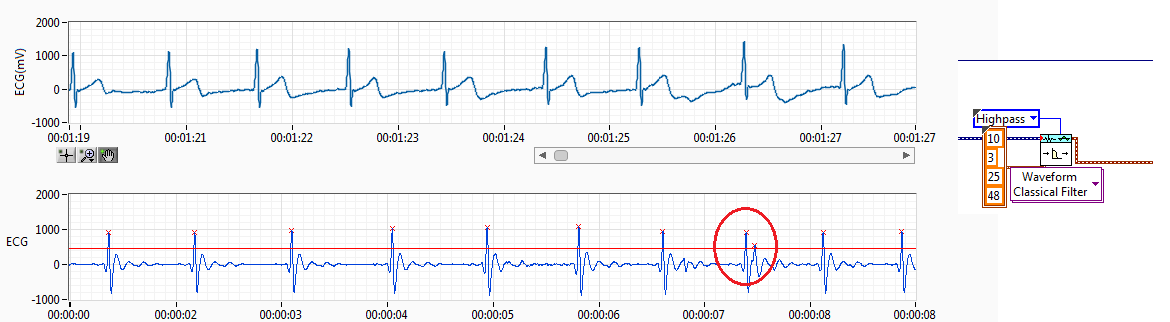
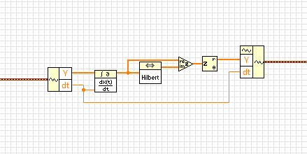
I have RCV of the ECG signal. I filtered the ECG signal and get the resource (interval between each pulse of ECG) records.
The source of the signal have noise I use a threshold but sometimes spikes of failure. Like the previous capture. Normally, if you get a pic of fault detected, I'll try to find this index to add to the left or right of the peak, normally I add to the lower value. This works if it has only a bad impulse between 2 good.
The problem come when I have more than a ridge between the two coupons.
Also, when the impulse of R a loss threshold I have trying to find the index and get 2 new reading making division 2 peak value.
I have attached the method I've used to adapt it. I only works if I have 1 Ridge added on real measures of R or pulse 1 loss R, when I have several pics no work.
I would like to hear an idea to make it work better. I don't like the idea of removing the value interval, I have 2 hours of reading and if I remove the values I have lower data outoput is why I tried to summarize or division of values to get the correct reading without losing any data.
Perhaps, there is any better filter for ECG of entry, so I have a R-own pulse and less noise between ECG pulses.
Any advice is welcome.
Best regards, Fred.
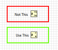
Almost. in the last step, you have extracted the real part of the complex waveform. Instead, you must retrieve the extent.
BTW, this idea isn't mine. I got from this article
http://www.ScienceDirect.com/science/article/PII/S0010482501000099
-
low Harmonic frequencies in the signal strength
Hi all
I try to know what are the causes of noise in my signal, whether it's a faulty hardware or my lack of knowledge.
The system that I'm actually consist of two engines not to not (parker HV232) that provide the uprising due to frost harmonic + pitch motion with phase shift of 90 degrees (a kind of movement of fish tail beat). I have a load cell 3 - axes attached to the shaft of the motor, pitch, and it measures up, drag and torque on a plateau which oscillates in the tunnel water (oscillation is provided by these two Steps). Tunnel to provide the incoming stream.
Signals of strength are captured through SG-23 + PXI-6221 daq card, I put the gain on the last of them to +/-200 mV for better resolution.
When the engines are turned off, the noise level on the static signal is the threshold of resolution, and nothing strange is not shown in the signal, and its ghosts.
The problems begin when I initialize the motion on the steppers, FFT of the watch signal of the low frequency spikes that are exact multiplies the frequency of oscillation, I have attached a PDF for example.
Disengage amplifier/filter which was suggested by manufacturing, and suspect I have observed could be due to this I'm not sure at 100%. The VI I use filter band-pass data in the 0.2 to 6 Hz, but somehow I can still see noise beyond 6 Hz.
I was wandering perhaps someone has experience with similar issues and can suggest a solution on how to get rid of these harmonics.
Thanks in advance
I'm not an expert in the dynamics of the tunnel, but from what you say, it looks like they can't be noise but components generated due to the rotation of a mechanical Assembly. Normally people refer to these harmonics in the form of 'order', which means that they are a multiple of the frequency of rotation.
So maybe it's the attacker
1. check by an expert (the one that includes the mechanical system that you are using) that to the point where you measure the force will not get the components of the order.
2. understand what exactly is the measurand. What exactly do you want to do with the measured signal (RMS, FFT etc..) Then you will be able to figureout if components of the order may affect your measurement.
Oleks wrote:
Disengage amplifier/filter which was suggested by manufacturing, and suspect I have observed could be due to this I'm not sure at 100%. The VI I use filter band-pass data in the 0.2 to 6 Hz, but somehow I can still see noise beyond 6 Hz.
During filtration, the attenuation in the band determines how fast the signals will be thinning of the hard shoulder.
-
Distortion of the signal caused by the channels # sampled and sampling frequency
I am using an acquisition of data USB-6211 (250 ksps / s) and looking at the sample channels 3s 80kS. (Labview 2012)
When I taste one channel, it looks fine (1 Channel_Sampled First_250kS), but when I add another channel to be sampled, the signal is driven down and that it depends on which channel is sampled (2 channels (Different) _Sampled First_40kS and 2 Channels_Sampled First_30kS). Addition of channel 3, it pulls down even more. I also noticed that the sampling rate also distorts the signal the higher the sampling rate, the more the signal is driven down.
The acquisition of data IS sampling of signals "correctly" when I run my Labview VI my external hardware begins to read in correctly based on the distortion of the signal.
What is the cause and is there a way to fix this?
I have attached the waveform above captures and can post some if necessary.
Thanks in advance,
WBrenneman
That's exactly what ghosts means. The measurement signals later is affected by other signals. It happens usually if you have a high impedance input signal. Adding pads like you can help solve this problem by making the signal to a lower impedance.
Ghosting would probably look worse to the frequency sampling rates higher, just as you said that you had problems, as it provides less time between samples of the amplifier set new voltage level when the multiplexer allows to switch between input signals.
Maybe you are looking for
-
What is the police & the key combination to get the male and female symbols?
-
laptop stuck at clear blue screen without a mouse
I have a laptop with Windows 8.1 17 envy and I tried to change the display settings after an application of the mouse and all the icons on the desktop disappeared trying to access the Task Manager, but the screen just switched to a light blue color w
-
How can I burn data on a CD - RW disc files?
I insert a CD - RW disc that is unused. The disk is not reformatted. How to format? If not, is there another way that I can put files of data on CD - RW drives?
-
Solid color behind the text of the desktop icons
Hello! Is it possible to have a solid color behind the text of the icons in Windows Vista/7/8/10 without using a third-party software? Thank you!
-
KB2952664 fails in windows update, error code 80242016
October 14, 2014 Windows updates had 15 recommended Important updates including KB2952664. WU appeared to run correctly, but when you restart found 14 updates installed successfully and KB2952664 failed with the error code 80242016 (usually means th