cDAQ inverted channels
When we test the material of MAX, output relay work correctly, but when we run the exe of LabVIEW, the relay outputs are swapped - write A, relay B relay lights.
We are moving (from CFP) to cDAQ with LabVIEW 2010. LabVIEW is on a desktop PC, target has not installed LabVIEW. The two machines running Windows 7.
Anyone seen this before?
What do you mean by "the exe of LabVIEW? Do you mean that you run LabVIEW in "development" mode, and within LabVIEW, run LabVIEW code? If so, please send the code. If this isn't the case, please provide details.
In my experience (limited), if I did in MAX, it has the same way in DAQmx/LabVIEW (unless I made a stupid mistake).
Bob Schor
Tags: NI Software
Similar Questions
-
Tektronix tds 3000 invert channel
I use the drivers to configure the oscilliscope between two experiences that I often change. I got wor except here n;' t seem to be a function to define a channel Invert on. There is a function matjh which claims to have some sort of invert but does not work. Any help?
It is a simple way to setup just read of the oscilliscope?
You can use the Write VISA function to send the
CH: reverse the order (where is the string you want to reverse. The MEASURE? query returns metrics. Consult the manual of the TDS3000 programmer. Ben64
-
How can I find a list of inner channel of a chassis or any other device using NOR-DAQmx?
Hello
I want to use the internal counter on my cDAQ-9178 channels. I know that I can use _ctro for my physical channel name when creating channel meter. Is there a way I can list all the internal channels available on a device. I use the function
DAQmxGetDevCIPhysicalChans
for a list of all channels of the device. But when it is used on the chassis, I do not get a list of internal channels. I found KB on how to do it with LABVIEW but cannot find a way to do it programmatically using NI DAQmx API C.
Best regards
Manisha
The MathWorks
Hi Manisha,
For the internal channels, you must hard-code them. You can find a list of the names of internal channels at the following link: http://zone.ni.com/reference/en-XX/help/370466V-01/mxdevconsid/internalchannels/
-
Suspension of a write operation to DAQmx
Hi all
I use a DAQmx with the cards NI9402 and 9264 to control current amplifiers for an MRI System. I intend to do using a waveform table raised on channel 3 of the NI9402 (high-speed digital input).
The difficult part is I need to pause the write operation once a given number of points was written until the digital signal is reset, how the rest of the buffer can be written.
I'm not satisfied with my current solution because it is ugly and is rather slow. There is a minimum of 70 ms between the operations of two scripts, which is not acceptable. I need a minimum waiting period of 10 ms.
I'm not familiar with Labview, but I think there may be a way to use the clock for this signal? Unless someone sees a better way to proceed?
All the best,
Lionel
Hey Lionel,.
I thought of a way to do this completely in hardware. You will need two counters embedded chassis cDAQ, 4 channels of your outdoor wiring 9402, and some (including a BNC T so that it works well). I briefly checked that this method works, but I have probably not thought through every possible corner cases. My code works as follows:
- Set up a finished counter of output to generate samples N, where N is the number of samples to produce after the initial rising edge of the trigger signal. Out of this train of pulses on channel 9402 0 (PFI 0). This task is to use the amount of 9402 channel 3 flank (PFI 3) as a starting signal.
- Set up a different output over counter to generate samples of M, where M is the number of samples to produce after the trigger signal goes low return (total of samples or less N). Out of this on the 9402 1 channel pulse train (PFI 1). This task should use the edge falling from 9402 channel 3 (PFI 3) as a starting signal.
- Using a BNC T, combine the PFI 0 and outputs 1 IFP then their thread 9402 channel 2 (PFI 2).
- For your analog output task, use a value over production task generate N + M samples with the clock set to PFI2 sample source.
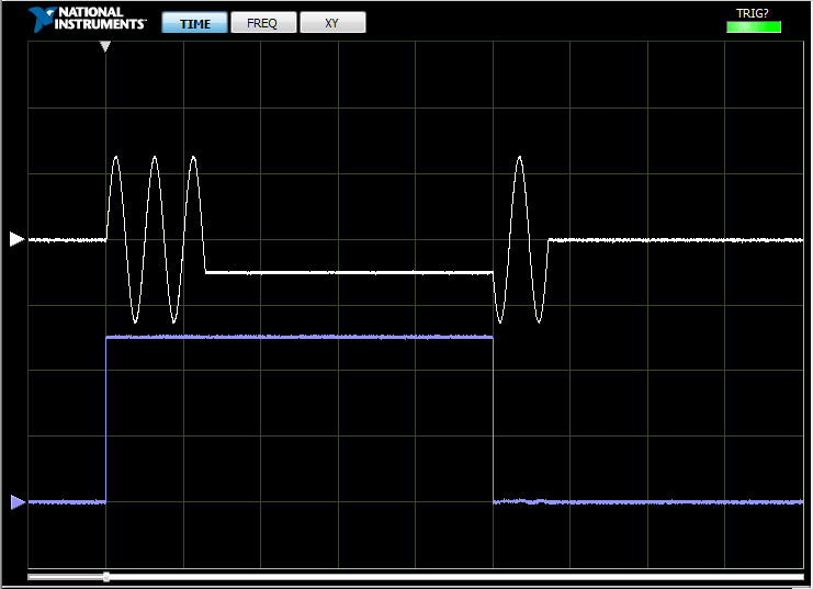
I tested it with an SMU-6363, assign a sinusoid point 4000 to 1 ms/s output. With N the 2567 value and the value of 1433 M, I got the following result. I can change the values of N and M, and it still works well.
I post my code, but honestly, I just did some quick changes to the over voltage output – over output and Counter – expedition of the examples (under DAQmx in the Finder of the example), so I don't know how much value he would add. Let me know if you have any questions well, or if this is not possible for some reason any.
-
Impossible to get more than 1 channel to read with DAQmx cDAQ-9172 under Windows 7
I have the cell load, voltage, and input thermocouple connected to a cDAQ-9172. My sensors entries have been scaled and verified in MAX, and all of them work. DASYLab 13, the driver is "dcDASY.dll" and the hardware configuration is "NI MAX.
When I add a task NEITHER-DAQmx Analog Input (that is, a set of scales) it appears correctly. If I add a second channel of the task and select it, I get this message:
'Channel of task name saved with the module is not available. DASYLab resets the module parameters for usable first channel name task. »
The name of the task remains the same for each new channel I have Add. If I change the name of the task by using the tab to the drop down menu, it says:
"You have configured several ways out for the module. If you modify the task, you lose the settings. You want to change the task? »
Both display the same data channels, and I can't work simultaneously several channels. It seems I missed something obvious, but I can't.The parameters are:
Measurement and Automation Explorer 4.6.1
NOR-DAQmx 9.0Material:-cDAQ-9172
Slot 1 - NOR 9215 (0-10 Vdc analog voltage)
Slot 2 - NEITHER 9211 (thermocouple)
slot 3 - NI 9481 (relay)
slot 4 - NI 9237 (entry deck w / excitement)
housing 5 - OR 9402 (DIO)
slot 6 - NI 9263 (0-10 Vdc output analog)Thank you
You can't perform different tasks (continuous) HERE on a single chassis. The first tasks that starts will be 'the resource booking '.
Combine the AIs of the various modules in a single task (see photo): start by creating the task of thermocouple. Then add AIs 9237 (e.g. Kraft) and 9215 (volts) using the button with the blue, symbol. Set the mode of synchronization of the task of "continue". Save the task, start DASYLab (second photo).
Change a task (adding channels, etc.) to the MAX while DASYLab works always, will result in unexpected behavior. To synchronize the configuration of MAX with DASYLab, you will need to close/restart DASYLab or use the 'sync' of the function (see photo 3 "syncmax.jpg"). You can set this function as a shortcut by right-clicking on one of the eight green or grey circle things.
You should think about an update of the MAX/DAqmx drivers. 9.x is a little outdated.
Updated at least DAQmx 9.9, better 14.x or 15. 0 (stay far 15 1.x).
-
Find channels and cDAQ modules
I have looked around the previous messages, but can't seem to find what I'm looking for.
In most of my experience, I've implemented some DAQ and once the modules and channels are all in place, which is where they stay forever.
Since I know things will not move, I create tasks in DAQmx.
I'm working currently on a new installation program, but the problem is that in things cDAQ will not be in the same place every time.
The application must read a number of strain gauges, which will be connected to the NI 9235 modules.
It will take place anywhere from 1 to 3 modules attached, and they can be in one of the 8 available cDAQ chassis slots 9172.
In addition, within a given module, anywhere from 1 to 8 channels will be connected.
So basically, I guess my questions are running:
(1) how many modules are connected and where?
(2) in each module, the number of channels is turned on and how much is empty.
From there on, I use DAQmx palette to take care of things.
Thank you!
So with every new start of the program, you will have a known device (your strain gauge device), but unknown channels. Here's how I attacked only a few years ago...
- DAQmx create a task to create a job.
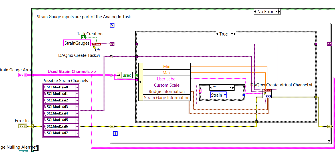
- Make a constant table of all known possible channels. Say that it is 8 cells and compare that to an array of channels USED, making false tracks off the chains 'Unused' and the names of real channel out of used ones. Under certain conditions to check which ones which is used to remove the appropriate channel and add the DAQmx virtual channels properly. The VI snapshot below goes into the details. I brought not only the channels, channels, such as min/max properties and bridge information. My VI also made bridge removal, under certain conditions, depending on sensor that the user wanted to null (that part is not shown.)
This code isn't super sleek, but I hope this gives you the ideas come from.
-
DAQ Assistant do not find channels of the cDAQ
We recently bought the Compact DAQ and two thermocouple modules 16 channels. I am trying to change a code to use a Pico USB logger for the cDAQ and I'm trying to follow the examples found on your Web site using the DAQ Assistant. Initializes the DAQ Assistant, and I choose analog input for the selection of Signal acquisition. When I select the option of Thermocouple temperature section, it says "reading of Lecture de Configuration Configuration of the system, please wait...". "but it never picks the cDAQ channels. I installed drivers and recoginizes of the USB port on the device (and the light indicates that it is in "ready" mode), but it has never been "Reading System Configuration."
Thank you for your time.
Solution has been found. It turns out that the data folder was corrupted files it contains. Once that I deleted it MAX started to work very well.
-
Sampling Multiple channels of unique cDAQ Module
Hi all
I am currently researching the use of cDAQ for a system of analysis of oil, especially the module OR 9201 for voltage GOT.
We have 6 entries SE located in the voltage/current ratings, although they all need different sampling frequencies. It is my understanding that the module is capable of 500 kHz, which will be split between entries.
The sampling frequency should divided equally? Or could I for example send a 250 kHz channel and split the rest between the other 5. Synchronous between devices is not necessary.
Many thanks in advance,
Peter
Peter,
See my replies to each ball:
- Am I correct in saying that I could taste each module to a different sample rate? Yes
- If I taste the 9201 to 500kHz/6ch, will I have an effective sampling frequency of ~ 83kHz on a given channel? Yes
-
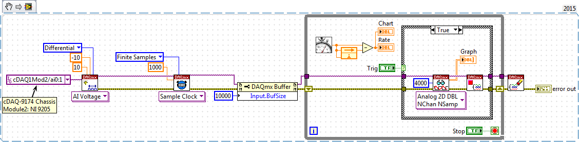
Not able to read 4000 samples the analog channels of cDAQ module (module NI 9205)
Please check the chart bloack (FALSE Structure box state a wait with 20ms function) and attached the code (saved in LabVIEW 2015).
On executing the code and using the button 'Trig', I can see only 1000 samples (for each channel) and not 4000 examples.
Please help me to understand what I am doing wrong?
Entry of son "4000" to "samples per channel" Schedule VI DAQmx. The default value when unwired is "1000".
-
inverted waveform channel values
Hello world
Anyone know how I can reverse the values of a tiara waveform channel? (practically activates the function of inverse matrix 1 d of Labview).
See you soon
Hi Saloutios,
So let's say your channel signals departure has waveform properties that define the X axis range from 0 up to 0.999 with a stage with 0.001, for a total of 1000 values. You ask how to redefine the properties of waveform so that the x-axis instead starts to 0.999 and goes down to 0 with-0,001 step width? If that's what you want, just redefine the properties of waveform like this:
Adjust the strings = Data.Root.ChannelGroups (1). Channels (3)

StartValue = Channel.Properties ("wf_start_offset"). Value

Increment = Channel.Properties ("wf_increment"). Value

Length = Channel.Properties ("length"). Value

EndValue = StartValue + (Length-1) * Increment

Channel.Properties ("wf_start_offset"). Value = EndValue

Channel.Properties ("wf_increment"). Value = - Increment
Brad Turpin
Tiara Product Support Engineer
National Instruments
-
I have a NI 9234 inside a cDAQ, and I was wondering:
Can I configure each channel individually, while measuring the two at the same time?
I want to have the excitement of 2mA enabled on a channel, but not the other I read / compares the two signals simultaneously.
So far, I have to choose Toggle both on a property node, and not what I need.
Thank you
Billy Murphy
I thought I'd share this email, I just returned from a very helpful employee at NOR :-)
-Billy
William,
You can of course! Please take a look at this article:
http://digital.NI.com/public.nsf/allkb/3AD6CCE935192B4086256F6B0079CB1F?OpenDocument
The last paragraph is the most relevant: If you want to have different settings on each channel used, the best thing to do is to create a channel DAQmx of different types of measurement for each of your different settings. These different channels DAQmx can always be used within a single task DAQmx. For example, if you have three starters of micro and single voltage, you can create a type of measurement microphone and a type of tension using the DAQmx create channel VI. The channel will be associated with three physical channels while channel voltage will be associated with one. Voltage channel can have different settings, factors, coupling, the fat and IEPE properties compared to the microphone channel.
Concerning
Katie Maddox
Technical sales engineer
National Instruments
-
How to initialize a cDAQ Ethernet (9188) to autostart?
Hello
I have a LabVIEW program that performs tasks DAQmx (pre-configured via NI MAX). The material is a cDAQ-9188, connected directly to the laptop via an Ethernet cable. Both machines have static IPS (same subnet).
Question
Whenever we turn on the machines, NI MAX notes that the cDAQ-9188 is reserved and running. However, the C Series modules are reported as Absent (error-88705 code: "the specified device is not present or is not active in the system.) The device cannot be installed on this system, may have been disconnected or may not be installed correctly")
As a result, the LabVIEW program generates an error, because the physical channels required by the DAQmx tasks are not.
Workaround
Each time we spend in the entire system, we're going to MAX OR -> my system-> devices and Interfaces-> devices network-> OR cDAQ-9188 and click "post."
The test always succeeds and seems to be a sort of boot behind the scenes. After this step, the LabVIEW program works without any problem.
Questions
- This behavior is expected? If this is not the case, what could cause this?
- Is there any way to automate this initialization, so that the user does not need to click on "Self test" after each cold start?
Hi JKSH,
You can the make a self-test program.
I wouldn't say that it is an expected behavior. What has helped here, was a repair DAQmx and LabVIEW. But before do you I'll make sure that you have the latest drivers.
-
cDAQ-9178 & NI 9401 - ASM: incremental Rotary encoder works is not beyond a certain frequency
I use a chassis with a NI 9401 DIO module 9178 cDAQ. I'm trying to convert the output of a rotary incremental encoder ASM (in radians) to rpm.
Sensing head (PMIS4-20-50-240kHz-TTL24V-Z0-2M-S)
Snap ring (PMIR7N-20-50-M-20)
The encoder outputs 2500 pulses per rev (output 5V TTL). The maximum speed which will see the encoder is 2800 rpm, which is equivalent to 2800 RPM * 2500ppr/60 = 116,667.67 Hz in terms of frequency.
Since the NI 9401 of the operations specifications:
Maximum of the input signal switching frequency by the number of input channels, by channel
8 input channels... 9 MHz
4 input channels... 16 MHz
2 input channels... 30 MHzI use only 1 channel, so I'm assuming that the 9401 should be more than capable of handling the 116kHz which the ASM encoder is spit.
Everything works fine until about 2100 RPM (~ 87, 500 Hz) but then I begin to see a drop in rpm, followed by a flattened behavior, then a slight increase. But never more than 2100 RPM. Our test unit is inspected for other reasons at the moment so I can't produce a plot of the behavior (I can reupload later). I think this must be a matter of aliasing with the meter or something of the sort. I have a digital filter set in place with a minimum of 4.0E pulse width - 6. It is two times smaller than the width of minimum pulse at a frequency of 116kHz (0.0000085714). I don't think this should have an impact on the calculation.
Any suggestions? This value of RPM is essential to our application.
Thanks in advance,
-MB
brown_ktr wrote:
I have a digital filter set in place with a minimum of 4.0E pulse width - 6. It is two times smaller than the width of minimum pulse at a frequency of 116kHz (0.0000085714). I don't think this should have an impact on the calculation.
A 116 kHz frequency, the period is ~8.57 us, but the pulse width half duty cycle of 50%. Ascent/descent time factor, and it is quite possible that 4 US is too long for your encoder signal.
The shape of this graph supports this theory, if we consider that there is variation in the exact pulse of each encoder pulse width. The shortest pulse is ignored when the filter starts to kick in, and the speed of ROTATION increases pulses longer and longer are ignored then as well.
Try to decrease the minimum pulse of digital filter (US 2 or even 1 US) width and see how it goes.
Best regards
-
Many signals with ditch (NI 9229 and NI 9205) devices multi 9188 cDAQ chassis
I use a chassis equipped with 9188 OR cDAQ with 6 x NI 9229 (6 x 4 HAVE simultaneous chnls sampled with aliasing filter) and a NI 9205 (32/16 HAVE chnls single/premium multiplexecd chnls). I created a simple mind task the DAQ Assistant to acquire 12 chnls with the module NOR 9229 modues and 4 with the NI 9205 module. A generator is used to produce a sine wave with a frequency of 10 Hz and an amplitude of 500 mVpp as input to all channels. The same generator also produce a square wave (synchron to sine) which is used as input trigger (PFI 0 - BNC connector on the chassis). The acquisition is expected to have samples end up a flow of 2 kHz and a datalength of 4000 samples (this means a time of acquisition of 2 seconds) controlled by a digital reference triggered with the cADQn/PFI0 as a source of relaxation.
My problem is the time difference between signals acquired with the NI 9229 module and those acquired with the module NI 9205 (see the attachment). The time difference is not constant and change when the frequency of the input signal varies. I guess the difference is due to aliasing filters used in the NI 9229 module and I'm looking for how to resolve the situation. Any help will be appreciated...
Philippe
By the research and reading, OR knowledge base I solve the problem by making a dummy read on the NI 9229 channels before reading from the device OR 9205.
According to the specifications of the NI 9229 module, there is a delay of filter (digital filter) of more or less 40 samples that are present only in the case of a digital triggering.
Reason and solution of this problem are explained here: http://digital.ni.com/public.nsf/allkb/F989B25FF6CA55C386256CD20056E27D.
I have applied the solution presented in this paper and this is excellent work.
Now, this problem is solved.
What about a whole, Philippe
-
How to connect the chassis cDAQ for strain gage
Hi, when I read the guide of the extensometer of wiring on a chassis cDAQ (http://www.ni.com/white-paper/7130/en) I found confusing fig 10 .
What are the things between the chassis and the extensometer?
The three wires go only one channel of the cDAQ chassis? (in Fig 10, on channel 0?)
Why there are four terminals (CH + EX + QTR EX-) on the strain gauge, but there are only two wires coming out of my extensometer? What should I do?
PS. I have a USB-4431 cDAQ and a Vishay extensometer (http://www.vishaypg.com/docs/11297/250lw.pdf)
Thank you very much!
Elly
ZSH2010,
The 9219 will work. You will need to use a measure of Bridge 2 son resistance measure quarter vs. For more information about how to use the 9219 for 2wire resistance measurements, take a look at the 11 and 15 of the document specifications page
http://www.NI.com/PDF/manuals/372407a.PDF
It will be slightly less accurate than the quarter for the 9237 bridge accessory, but still needs to do the job.
Kind regards
Maybe you are looking for
-
Deskjet 710/720/810/820/1000 Series printers - Patch for 64 bit Vista and Windows 7
There is a problem with the 64-bit, Vista, Windows 7 and Windows 8 or 8.1 drivers which causes the spooler crash with the following HP Deskjet printers: DeskJet 710 DeskJet 712 DeskJet 720 DeskJet 722 DeskJet 810 DeskJet 812 Deskjet 820 DeskJet 822 D
-
"Stop" Windows function does not work correctly
My windows stop does not. I can only close by manually pressing the power button or by Log off-change user-windows stop - stop. Pls help.
-
Need for a disk recovery for Equium A100-549
Hello Recently, I tried to restore my laptop to its factory settings. However, the recovery cd stopped working after it has begun to wipe my hard drive and does not complete the task. I don't think that the cd will work more. My computer now with no
-
Double the number of one-digit display figure
Hi all I was wondering if there is a quick way of numbers of showing a number between 0 and 9 as 00-09. Best, Kutal.
-
Is there a specific order for the way the slideshow takes your photos from your phone? I have never installed a slide show, and whenever I have to dock my phone to load, a slide show starts. I'm just curious as to how he takes pictures to display. Ce