Choose and place using labview and or vision acquisition
Hello world
I'm doing a project studying on Vision guided pick and place of a robot (abb) industrial. I would like to know the steps involved in the creation of the block.
I locate the object, move his webcam cooordinates. Then made a pattern match, and would send the cooordinates to the microcontroller. then from microcontroller for control of robot... then the industrial robot should choose the object and place it in a predefined area...
I would be extremely grateful if you guys can help me because I am new to LabView.
Thank you
Pradeep.M
What you describe is quite complex, but here are a few tips. The key is to establish a correlation between the coordinate system of the robot to the coordinate system of the camera. I guess that the camera is statically located above the pick-up area? I move the robot at each corner of the frame to its choice position vertically and note the position of the robot at these locations. These 4 points in space will be correlated to X, coordinates of pixels in the camera image. Basically, you need to write a sub - VI with entries being pixel X and is coordinated and coordinates output being the robot.
Writing a test application saying the robot to get pixel location to any X, Y in the framework to test your Subvi. If this does not work, then you need to set up a correspondence to the model. You probably want to do a geometric pattern match. Take a look at this example: http://zone.ni.com/devzone/cda/epd/p/id/5555
You will need your pattern match algorithm to return both the coordinates for your robot, and the orientation of the tool needed for good pick up the object (if the pick-and-place robot tool requires to be in a specific direction). If it's basically up to you will convert the object X, Y and rotation angle in the framework that you receive correspondence from model to any coordinate system, the robot uses.
The placement algorithm could be simply an adjustment of orientation to the object being investment and then investment positions could be an array of coordinates of robot which you browse after each pick.
Be sure to implement security mechanisms in your algorithms so that the robot can never go somewhere outside of a safe range of coordinates.
Tags: NI Hardware
Similar Questions
-
How to randomly choose excellent data using labview.
A very good day to all. I am currently working on a system that will be selecting whole number of together generated at random in number. If this is not possible, I would like to the system to be able to select the number of the set of numbers that have already been generated randomly from excel. kindly help me with the solution. To get clear, assuming I put numbers 1 to 10, I want a labview setup that will recover these numbers one after the other or with replacement without excel or auto generated. I know it's possible in matlab, but would prefer if possible labview. Thank you
More, otherwise all of the languages that I ran across were a rand() function returns a random number between 0 and 1. Get some other range belongs to the programmer. The usual method is to multiply by the beach, you need and add an offset to adjust the average. For example, if you need a random number between 200 and 300, the formula can present themselves as "rand () * 100 + 200". " If you need an integer, you can use the round function (who, it will remain as a float with no decimal pportion) or conversion (all). All this is feasible and direct in LabVIEW. Take a look: http://digital.ni.com/public.nsf/allkb/FCCDCD678EEF3A9186256D7B008054F5
If you feel more comfortable using a file, try this: http://digital.ni.com/public.nsf/allkb/C944B961B59516208625755A005955F2
-
Of image processing and machine vision do not appear in the function Palette
Hello
I have the problem and I can't solve
Of image processing and machine vision do not appear in the function Palette, although I have implemented NEITHER imaq and NI Vision Acquisition why?
Can someone help me?
Vision Development module is the package that contains the entire library of Vision.
-
Orders using choose and @inlines together
I am looking for help on how to structure choose them by using @inlines. I can get @inlines to work with, IF statements and me can get CHOOSE / WHEN working on it has, but I have a few places where I need to use the combination to CHOOSE and set INLINES. I tried several options but can't seem to find the magic combination.
Thanks for any help
MatternThis example would help?
No number of
Thank you!
-
I want to send data using labVIEW to arduino using write visa and the process and to take action using arduino. After that, I want to arduino to send out necessary via a serial port to labVIEW which should be read using visa read and store in a chain. While I am able to write or read both individually, I can't do it consecutively. I used advanced read and write vi for checking my code, but nothing is helping. The wrong bed 'time delay before execution. " Please let me know where I can go wrong. Also is it possible to write code for hx711 using labVIEW
1. you need not "\n" on your orders println(). This command adds an end of line character already in the message.
2. you get the error because you have a loop around your reading. After the first reading (well technically, the second because of you add an extra line end character), there is nothing left in the port. As a result, you will get the timeout.
3. you should really consider using a Structure of the event. This way you just don't write and read when you press the Write button and you can also use the structure of the event to make the loop to stop. I also go up to close the port inside the stop-> value Change event.

-
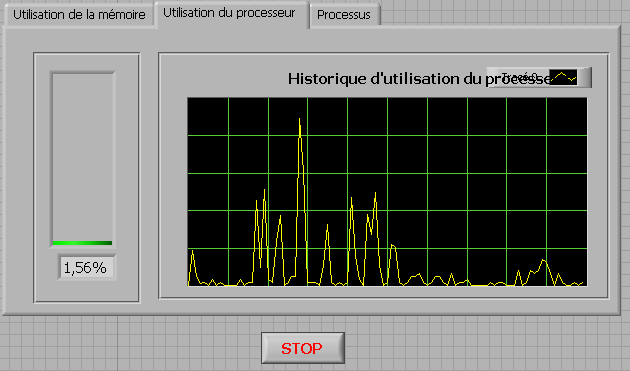
How to check the CPU usage and paging using LabVIEW
Hi guys,.
I build an application that is used to check the CPU usage and paging using LabVIEW. How can I do?
any help, suggestions or advice will be greatly appreciated...
Kind regards
Prashant
Hello
If you plan to build your app for Windows, you can use .NET classes. (System.PerformanceCounter), there is a simple example with LabVIEW:
C:\Program NIUninstaller Instruments\LabVIEW 2010\examples\comm\dotnet\SimpleTaskMonitor.llb
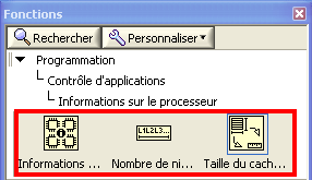
Also, you have several screws that you can use to verify information about the processor.
Kind regards
-
Time real ADC/DAC for SMPS by using Labview and USB
Hi all
I asked the Sales Department of this same question, so here's a two-pronged approach:
I am reserching a control algorithm for power switching, and so far, its performance simulations seem to be good. Now, the goal is to implement the circuit from the experimental data.
I've seen several NI USB DAQ boxes that seem to have the performance, I'm looking for (for example, the box USB-6211 a sampling rate and resolution I need).
The control algorithm uses the following mathematical functions: add/sub/mult/div/exhibitor and derivative/integral.
My question is this: is "strong enough" Labview take four-channel data 250Ksps, crunches the numbers in an equation and spits out the answer to an analogue on the channel, while time REAL? I'm looking for a rate of analog output of ~ 100 kHz.
Thank you for any suggestions you have!
-Rick
Hey,.
So if you were trying just to perform an input or output, then the box USB-6211 would certainly be able to treat it as the machine clock could manage the inputs/outputs, no software. However, what you are wanting to do, basically a feedback system, he will have to avoid (at least to a USB device) because you need to be able to specify Active which is the output. So, for this reason alone and the fact that you want out of 100 kHz, this device and the USB devices in general will be not an option any what software you use, LabVIEW or otherwise. On another note, you want to make sounds more like live update, not in real time, which is more on the jitter. Bottom line, for these kinds of requirements, you might need to move to an FPGA card, something like the NI PCIe-7841R would work. It's more expensive, but for your needs, FPGA will be the only option and it comes down to the latency of the bus, but also the response time of software. With FPGA, as shown in the first scheme of the following document, you basically close your software through hardware loop.
Basics of FPGA
http://www.NI.com/white-paper/6983/en
-Ryan S.
-
Deal with failure when using LabVIEW 2011 and DSC MODBUS communication
I'm currently reading from operating records a PLC with MODBUS/TCP. I confirmed that the PLC will update the values and in response to a MODBUS communication correctly by using a third-party program called Modbus Poll. However, when I try to query the PLC using the LabVIEW shared variable engine, I am unable to read the values of the same addresses that I consult with Modbus Poll.
My installation is simply to a PC directly connected to the controller via Ethernet without a router between the two. I'm using LabVIEW 2011 SP1 with the DSC module.
I opened the Manager of distributed systems OR to display the State of all variables in the Modbus Library that I created, and I noticed that the ILO CommFail permanently the value 'true '. All other variables with a 'read' access mode signal "failure of process". I tried to restart the process and stop and start the local variable engine without success. I also restarted my computer several times to see if any services did not exist, but this does not appear to have solved the problem.
Finally, I resorted to listening to communications on the network card I have the PLC connected via Ethernet using Wireshark and found that while Modbus Poll communicates with PLC, number of MODBUS and TCP packet is sent and received. However, when using only LabVIEW or the DSM OR communicate with the controller, there don't seem to be any communication on the network card.
Something that may be interesting to note is that I could communicate with the PLC and to read values with the DSM just once, when I understood everything first what address I should be reading of. All of this has stopped working shortly after. Prior to this, 'CommFail' was not generally set to 'true' with my current setup. Thinking it was my firewall, I have since disabled my firewall, but this seems to have had no effect on the problem either.
Any help on this would be appreciated.
So, I thought about it. It turns out that the IP address of the server i/o MODBUS must be set to the address of the MODBUS slave, not the local computer. The address of the i/o MODBUS server is defined by the navigation in the Explorer window projects, expanding the variable engine shared library for MODBUS and right click on the server MODBUS (for example Modbus1) item and select Properties.
In addition, the addresses seem to be shifted by + 1.
Thanks for the tip so.
-
Complete equipment of simulation using LabView, Multisim, and MAX (easy answer accepted!)
Hello, all!
Sorry, I'm new, but I checked around for a definitive answer on this, but I'm not 100% sure. I learn LabView for a physics of upper-division course. We use hardware (DAQ - MX) and a mixture of laboratory equipment - mainly stuff such as voltmeters, oscilloscopes and test setup with simple components. I also work with NIM instrumentation, but that's secondary to my needs here. So, when I'm away from the school, is it possible to make a complete simulation of my classroom work using LabView, Multisim (for my model) and the measurement and Automation Explorer (for the acquisition of data-MX)? I know I can create a circuit and drop it in Labview, but I'm not sure on the acquisition of data. I hope for what is a "seamless" reconstruction of what I do in class. I can't take a simple 'yes' or ""; as long as I know it's possible, I can find the solution.
Thanks for the help!
I wrote 'sim' screws in many situations where I need to work away from the hardware store. I think that MAX has a few features, but you may be limited in the types of signals, you can simulate.
For my sim screw, I make a copy of the original VI with ".sim" added file name. I also change the icon in a characteristic way to identify the version of the sim card on the BD. In this way the two VI have the same connector pane and are interchangeable on the BD structure. disable the diagram can be your friend here. Inside of the VI of sim, I generate the signal in any form I want. You can also add additional if necessary controls.
Lynn
-
I am new to the ethernet communication using labview. I don't have any material. I have two laptop, I need to send and receive data through these 2 portable by using labview. Kindly help me on this.
Dennis has already said: for a direct PC - PC connection, you need a cross over cable. If you connect through a router or a switch, you use a standard cable.
-
my button is not the top of my list of contacts - when I start typing a name, a list does not appear, for me to choose and my spell checker does not work
Hi Lynn,
What mail client do you use?Using Windows Live Mail or Outlook?
For Windows Live Mail:
The best place to ask your question of Windows Live is inside Windows Live help forums. The experts he specialize in all things, Windows Live and I would be happy to help you with your questions! Please choose a product below to be redirected to the appropriate community:
Looking for a different product to Windows Live? Visit the home page Windows Live Help for the complete list of Windows Live forums at www.windowslivehelp.com.
For Outlook:
If you are not using one of the people then please let us know what you use so that we can help you further. -
Vision and motion-Vision of the problems of public services
Hello, everyone
I wrote a program to LabVIEW 2009 SP1 (Professional Development System), also I have the Vision Acquisition software (November 2009).
I developed this code under windows XP, I test before you deploy and it was OK.
After I deployed it, I install on touch Panel PC (with Windows XP Embedded), after I installed, it ask me vision acquisition software license, I activate over the Internet, and he succeeded.
When I run the program, I'm dealing with these messages:
Error-1074396157 was held at IMAQ Cast Image
Unauthorized copy of Vision OR
Possible reasons:
IMAQ Vision: Unauthorized copying (Hex 0xBFF60403) of Vision OR
When I delete the vi IMAQ Cast of my code, deploy the code and install it again, my program worked fine as I want. but I need to use tools, (I have a tray also with resampling of Image, but also error)
Commercial vision and movement-Vision-Image Manipulation - resampling
could you tell me what is the problem?.
Thank you
Hi Al-Zahrani,
You have the Vision Development Module on your development computer as LabVIEW and Vision Acquisition software? Also, could you confirm that the screws are work and does not?
IMAQ SetImageSize IMAQ GetImageSize and IMAQ create work without error?
IMAQ Cast Image and IMAQ resample do not work and the license error is produced?
If this is the case, I believe that it is due to the fact that these screws are included in the Vision Development Module (see screws that are installed with OR-IMAQ and Acquisition of Vision Software). In order to use them on a remote computer, you must have a license for the execution of Vision engine.
Lynn
-
Problems with typedef uInt32 and NI Vision
Hello
I'm having a small problem my request against the headers provided by NI Vision acquisition 15.0 and CVI 2012SP1 of construction. The problem seems to be contradictory typedefs in the files of headers associated with the types of 'SESSION_ID' and 'uInt32 '. In NIIMAQdx.h, it is the following:
#ifndef _NI_uInt32_DEFINED_
#define _NI_uInt32_DEFINED_
#if defined (_MSC_VER)
typedef unsigned long uInt32;
#else
typedef unsigned int uInt32;
#endif
#endifNow, _MSC_VER is not defined, so we get defined as an unsigned int uInt32. In niimaq.h there is:
#ifndef _NI_uInt32_DEFINED_
#define _NI_uInt32_DEFINED_
#if defined (_MSC_VER)
typedef unsigned long uInt32;
#elif __GNUC__
#if __x86_64__
typedef unsigned int uInt32;
#else
typedef unsigned long uInt32;
#endif
#endif
#endifWhich neither _MSC_VER or __GNUC__ being defined, does nothing except set _NI_uInt32_DEFINED_ who prevernts to be set by another heading. niimaq.h also has this in it:
typedef uInt32 id_interface;
typedef uInt32 SESSION_ID;
typedef uInt32 EVENT_ID.
typedef uInt32 PULSE_ID;
typedef uInt32 BUFLIST_ID;
typedef Int32 IMG_ERR;
typedef uInt16 IMG_SYNC;
typedef uInt32 GUIHNDL;This means that, by itself, a module which includes niimaq.h build because uInt32 never gets defined. You can include NIIMAQdx.h in front of her then she cand defrine uInt32 (as an unsigned int), that works, except that nivision.h has this line int he:
typedef unsigned long SESSION_ID;
Yet once they do compile due to the conflicting types (unsigned int versus long unsigned). It seems that there is no way to include niimaq.h, nivision.h and NIIMAQdx.h in the same .c file, regardless of the order, without certain types of conflicts or unknown. Comparison of return to an older version (3.9.1), I see in NIMAQdx.h,
#ifndef _NI_uInt32_DEFINED_
#define _NI_uInt32_DEFINED_
typedef unsigned long uInt32;
#endifWhich is nice and simple. niimaq.h also has the same code in it too much OR-IMAQ 4.6.1. Does this mean that I can "fix" it by defining _MSC_VER, indeed put
#define _MSC_VER 1300
At the top of my .c file gets in effect of things to build, but I'm wary to do this because I know there are other things that seem out of it.
Any ideas or is the solution to restore an older version of the Acquisition of the Vision? Thank you.
Hi Tanner!, thanks for the reply. I use the Debug, not 32-bit mode. The code example you provided does not build in my configuration. The problem is this code in niimaq.h
typedef uInt32 id_interface;
typedef uInt32 SESSION_ID;
typedef uInt32 EVENT_ID.
typedef uInt32 PULSE_ID;
typedef uInt32 BUFLIST_ID;
typedef Int32 IMG_ERR;
typedef uInt16 IMG_SYNC;
typedef uInt32 GUIHNDL;And the reason is that an Int32 and uInt32 are not defined (although uInt16 is defined). On another PC with NI Vision 2009 installed it relies very well, but it does not work on this PC with IMAQ 15.0.
Play with it, I think the problem is that CVI 2012 SP1 isn't definition _MSC_VER or __GNUC__, whereas CVI 2013SP1 __GNUC__ defined as 4 (and indefinite _MSC_VER leaves). As __GNUC__ is defined, then in niimaq.h, uInt32 is defined as unsigned long (for 32 bit), and all is happy with CVI 2013, so the problem seems to be related to the combination of the ICB 2012 and versions more recent the IMAQ.
-
Overview: choose where place such as a circle or a text
I used to be able to select the tool for editing (for example, the circle or the text), and then click in the PDF where I wanted it to go (according to official instructions: Select the text tool, and then click in your document where you want to place a text box.) You can then type text in the text box).
Now, as soon as I click on an editing tool, it immediately and automatically be put in the center of the PDF without my power to choose the place; I then drag to where I want to.
How to return to the normal preview behavior? TX
Unfortunately, I don't think you can. I agree that the old way of doing it is much better. I can do more than send comments polite to Apple and let them down we would like that the old functionality back. http://www.Apple.com/feedback
-
waveform, with an average of results using labview to O-scope
Hello fellow engineers! I'm a first-yeargraduatestudent in CHEE at the University of Houston. Basically, I know nothing about labview. I am trying to program an application that looks like this - I collect a waveform of the signal of O-scope. This waveform does not change its characteristic shape. I need to find the wave form average of waveforms of N (100 for example). Thus, the slight changes (or noise) in the feature of form during the period mustbeaveraged out and I need to have a resultant waveform that represents the average waveform over a period. So, basically, I'm collecting the wave several times (for example 100) on a single period. The O-scope that I use now is Tektronix TDS 2024 B. It communicates with the computer via USB. The version of labview is 8.5. For now, I am able to communicate with the computer using our o-scope through labview. I already downloaded the driver of instruments of your Web site. It turns out that the program can give me only the average result I can get directly from o-scope manually. I need to have more say on average (100) using labview. I wrote a program that relies on the instrument driver that is downloaded on your website (for loop part is average, the waveform). The program that I modified and an instrument driver are attached. The program cannot be fully open, if the driver is not put in the right place in the labview (under lib inst.) When I run the program, the average waveform does not appear on the front panal and signal waveform file is not saved correctly. Is there someone can find where I did wrong and it develop for me? Because I barely know Labview, it will be even better if you can add an image or program that you have changed. I'm waiting for your creative ideas.
With the best regards,.
--
Weiye
Maybe you are looking for
-
Having to hold R to select a portion of a clip
Since the last update to iMovie, I discovered that you must hold the 'R' to select a portion of a clip. It is VERY annoying, does anyone know a way to put back in place to click and drag to select a part of the clip? Or I'll just have to put somethi
-
After the upgrade to win7 and sometimes having a blue screen when you start the following happened. After blue screen once more, laptop is not starting at all. The only thing that happens is that I see the upstartscreen (in touch with tomorrow TOSHIB
-
Why can't unlock my computer with the password
I can't get my computer unlocked the password and when I put my password I get this message. the user profile Service service has no log that user profile cannot be loaded... ideals why?
-
I lost my files in my outlook express Inbox. How can I get back them?
I lost my files in my outlook express Inbox. How can I get back them?
-
Question: what is a yellow circle near the batttery indication means?
Hello! I bought a 8 GB Sansa Clip today from Wal-Mart. It has the latest firmware 2.01.16 and was fully charged out of the box. A small yellow circle appears immediately to the left of the battery icon - on the top line of the screen. I couldn't find