cluster different rowid
Hi, I have two tables t01 and t02 both of them have the id column that the cluster column. But some same IDs have different rowid (data block address) why? What is a reason could explain you?
Select a.id, b.id, a.rowid rowid01, b.rowid rowid02 t01, t02-b where a.id = b.id order by a.id
ID ID ROWID01 ROWID02
---------- ---------- ------------------ ------------------
1 1 AAAXFMAAGAAAADjAAA AAAXFMAAGAAAADjAAA
2 2 AAAXFMAAGAAAADjAAB AAAXFMAAGAAAADjAAB
3 3 AAAXFMAAGAAAADjAAC AAAXFMAAGAAAADjAAC
4 4 AAAXFMAAGAAAADjAAD AAAXFMAAGAAAADjAAD
5 5 AAAXFMAAGAAAADjAAE AAAXFMAAGAAAADjAAE
6 6 AAAXFMAAGAAAADjAAF AAAXFMAAGAAAADjAAF
7 7 AAAXFMAAGAAAADjAAG AAAXFMAAGAAAADjAAG
8 8 AAAXFMAAGAAAADjAAH AAAXFMAAGAAAADjAAH
9 9 AAAXFMAAGAAAADjAAI AAAXFMAAGAAAADjAAK
10 10 AAAXFMAAGAAAADjAAJ AAAXFMAAGAAAADjAAJ
11 11 AAAXFMAAGAAAADjAAK AAAXFMAAGAAAADjAAI
11 selected lines.
The rowid is a method to treat a row in a table. Internal components must be hidden, you shouldn't care about them.
To understand this, just assume the rowid is something like the physical address of the database. It seems that t02 stores its rows in order physics 1,2,3,4,5,6,7,8,11,10,9. Which would explain the difference, you have observed?
Tags: Database
Similar Questions
-
Hello
I have the following problem.
I have a PC and a laptop, both with the same Installation and configuration.
On the laptop, the visualization of a cluster differs to the PC. It is bigger and not everthing is visible (e.g. scroll bar).
Also the lines are not on the same level.
At abnybody any idea why this is the case?
Take a look at the photos attached.
THX.
The computer of the latter parameter has large fonts in display properties.
/Y
-
A point of view composer for 2 HA/DRS-Cluster or 2 data centers?
Hey,.
I have a question of design, on a separate installed View Composer.
Is it possible to use a view of the Horizon with a vCenter and a View Composer environment, so that I can create view in desktop computers
(a) two different ESXi Cluster in the same data center?
(b) two ESXi-Cluster different, who are in their own dedicated data center?
It would be nice to get a useful response.
Best regards
André
Hello Andrew
It is possible to deploy desktop computers view in two different groups in the same ms as well as two different groups under different domain controllers. However, where are deployed clones full and linked clone depends on where the image of the mother or the model is present. If the view desktop computers that are in the same pool will be deployed where the master image is present.
-
vMotion is a failure for virtual machines
I'm trying to migrate virtual machines to one ESXi to another in the same cluster, it fails in the first stage. Storage and networking are shared and other same cluster different host machines have been migrated successfully. One could suggest?
Are you a specific error when migrating?
It's a failure at the end of specific percentage?
Have you checked reverse migration between different host and no host work?
Check if the nucleus of vMotion port is accessible from both ESXi hosts.
If vMotion IP is not the ping requests, check if the IP configuration is correctly performed according to the standard.
If the IP configuration is done correctly, try unchecking and rechecking vMotion core port of two hosts, it should work.
Also check that vMotion does not work on dVS and Standard with different IP configuration.
-
Difficulties in the identification of duplicates when inserting new records
I am inserting new contacts through Web Services... Use: Fname Lname, as WorkPhone, HomePhone, ExternalId and IntegrationId.
Everything looks ok... contact is created.
The problem is that if I submit the same soap, the same rendering message again (with a different rowid is created). And once again... a 3rd.one.
I checked the documentation for the main user definitions, and I think I properly but OD does not identify the double insert.
Pls. no clue on how to fix this?
TXS.
AntonioHello Antonio,.
There is no check duplicate for either through the UI or through WS Contact records. CRM On Demand imposes no constraints of uniqueness on any of the fields individually or in combination, you indicated in your message. There are constraints of oneness through import (for online help):
Contact
* Surname, name, work phone # and EmailOR
* External ID (created by another software system)OR
* Online ID (Oracle CRM On demand ID)NOTE: Oracle CRM On Demand does not check for duplicate records when the contacts are created through the user interface.
Thank you
Sean -
Parameters of different Cluster OR XNET (Hex 0xBFF6309A)
I've updated OR XNET on my system and the goal of rt and now I get this error:
Pible reason (s):
NOR-XNET: (Hex 0xBFF6309A) interface has already been opened with different cluster settings as those specified for the current session. Solution: Make sure the settings of the cluster of agreement for the interface, or use a different interface.
MPCC,
Can you click the CAN Port in the system definition and make sure that the Cluster settings have been kept? I saw this option to reset before.
-
I have a chart single 2D out a conditional of a loop indexing output such that over the rows of the table are not the same size. -Basically, they have different starting and ending points and sizes. -Not so concerned by the endpoints, because as soon as I get correctly starting points, everything shows fall in place.
The challenge is that when I try to have the variable t0 (start time) for each line, the wave of construction vi form would always keep each line at the same starting point.
I used the approach bundled with success (the cluster approach ensures that each waveform starts at different times according to the guidelines of my t0 defined for each line) but then I'm not able to get in the channel names I could make using the graphical approach (wave generation) waveform.
In essence what I get here, I'm losing here.
Because I don't want one of my mentors, Bob and Altenbach have fed up with me I have attached a vi this time

Attached VI shows a combination of the two attempts (first with the waveform graph) and then with the graph of cluster
1. with the first (graphical waveform), I get my channel names as you wish, but the alignment of the wave is not correct.
2. with the second (graphical cluster), the alignment is good, but I can't do the names of channel in the chart, even if they are present in the cluster.
I read some reviews that mentions that attributes can be displayed with waveform and data Dynamics (not clsuters) so I guess that's why.
I saw another report indicating the start time for a waveform 1 d will always remain the same for the rest lines defined for the first line even if changed for the following lines in a loop.
So I guess my question is: what is the way around questions like that?
First of all, let me be the first to the congratulate and thank you for finally posting a code! I'm not 100% certain I understand your question or your code, but I have an idea, perhaps, of what you want to do, so I wrote a little VI who made something simple that could be relevant.
You mention waveforms of different lengths and beginning at different times. You also want everyone to have a unique attribute (although I'm not sure what you want to do with the attribute). So, I did the following:
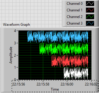
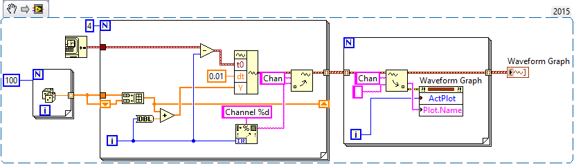
- Generated an array of 100-sample random to represent one second of a waveform.
- Created 4 waveforms on this 100-sample basis. The first waveform (channel 0) is just these 100 points. The second, 1 channel, is the concatenation of string 0 with the base of 100 samples, or a waveform "double". Channel 2 is 1 string concatenated with the base, and channel 3 is 2 string concatenated with the base.
- In order to trace the four channels that they rest 'on' the other, the waveform has the number of the channel added to it. Channel 3 is 3 + (4 copies of the basis of 100 points), a waveform 400-point random centered around a shift of 3.
- All channels have dt value 0.01 (but I guess I could have varied, as well).
- To make the channels start at different times, I started channel N N seconds before channel 0 (by subtracting the index of the loop, I, T0).
- For each channel, I created an attribute called "Chan" equal to "Channel N" (where N = 0, 1, 2 or 3, as the case may be).
This is the plot that results. Scale X is the absolute time value (no Date) using the 24-hour HH: mm
 S format. You can see that the plots are 1, 2, 3 and 4 seconds of time, and are offset from each other by a second. I used the trace attributes to change the name to the respective attribute.
The code to do this is very simple - I almost don't need to show it, because I think it is completely described by the text above, but this is here:
Now, it was not that much faster that some of your previous posts, when you refused to your postcode, "guess us" what you wanted (but not to not correctly guess), you tried to "push" us in the right direction (still refuses to post code), and no one seemed very happy?
Bob Schor
-
How to convert an array of string elements to a cluster with elements named different data types?
I'm looking for more help with the conversion of an array of elements of the chain in a cluster containing elements named different data types.
I am importing data from an Excel worksheet. He is coming in LabVIEW as separate (channels) 3 tables: 1) Variable name, (2) three possibilities Int, double, String) data type and the value 3), with the clues in each table corresponding to a separate variable (I have about 180 variables to import). My ultimate goal is to convert the string array of 'Value' in a cluster. But I want the correct data type in the cluster and I also the elements of the cluster name to match with the string 'Variable name' table so that I can use the Unbundle based on the name in my main VI.
Please see attachment a Subvi for more details. I did the size of the new items of tables 5 for simplicity. I realize that labels property cannot be changed during execution and I don't think I need to do. I just want to use the production cluster (mainly the unbundle by name) to help design my main VI. I will need to 'read' and 'write for' the cluster during execution, but I won't need to change the names of the items.
I was also wondering if there is a better way to import data from Excel? Is it possible to import directly into a cluster immediately rather than put everything as strings? I have attached a Subvi showing how I currently bring in data (found on the forum somewhere). It comes as table 2D, which I divided into 3 separate tables that I mention above.
I am open to any suggestion. Thank you very much.
-Mike
Instead of trying to create a cluster, I think I would use only variant attributes.

-
Initialize the cluster with data types different (lots of data)
Hello
I have data, which are composed of different data types. First of all, I have initialize cluster with these types of data and then "print" to light (photo). In case of photo data carries 8 characters than ja 4 floats. It was easy to initialize, but here's the question: How can I do this even if I have data that look like this (interpreter):
floating point number
name char [32]
Short value [16]
What I create loooong cluster which have a fleet of 32 characters, 16 short films? Or I can create these 'paintings' in a different way?
THX once again
-Aa-
I suggest using the table-cluster and configuration of the cluster size to match the size of your berries, then package these groups together. In terms of storage of LabVIEW, there is no difference between a group of
floating point number
Name1 tank
name2 tank
...
short value1
short value2
...
and a bunch of
floating point number
-> cluster shipped from
Name1 tank
name2 tank
...
-> cluster shipped from
short value1
short value2
So you can use the cluster table to get the right sizes rather than individually create all these values in a single giant cluster.
-
Constant error cluster appears different in two places on a block diagram
I am a newbie to LabVIEW. I took Core 1 and 2 and Vision and I did not com on this before.
The right image is of course a constant of cluster of error used in the block diagram to create a cluster of error and it lead to an error on the terminal. As far as I can tell the left image is the same thing, but why is it different? The causes of different appearance raises a concern that there is a difference in behavior that I don't understand. LabVIEW help season both are constants for error. When I create a new constant of error, it always appear as the image on the right above. I was not able to create something similar to the image on the left.
Could someone please confirm what the image on the left on a blck diagram?
Thank you
Bill
The left image is a mistake of cluster control. He has a presence on front panel and can be set via the front panel or by a property node or a local variable. The image on the right is a cluster of error constant. It is a static value.
-
Different databases with the same name in 1 cluster?
Hello classmates of dba,.
I wish to discuss with you the following situation:
We have a 4 RAC Cluster node.
Databases node 1 and 2 contain the 11.2.0.3 (Enterprise Edition)
Databases node 3 and 4 contain 11.2.0.4 (Standard edition)
12.1 GI on all nodes and all are part of the 1 cluster.
OS: Oracle Linux 6.5 (with + ASM)
Our company wants to migrate databases EE 1 and 2 to 3 and 4 nodes node:
-Downgrade of EA to itself
-Upgrade 11.2.0.3 to 11.2.0.4
Normally I do this by creating databases with DBCA under a new name and migrate data using Data Pump.
The problem is that the company wants to have the same name of database on all nodes.
Is it possible to have the same name of database on all 4 nodes simultaneously (from 2 houses of Oracle RDBMS different with different versions while all 4 nodes share 1GI?
It is a method of support?
Let's see if I can describe it more in detail.
You have a database named ORCL in your RAC environment. Create a new blank database named SLAVE_PORT_NUM. Perform a dump of export of ORCL and import in SLAVE_PORT_NUM. At this point, you have the data in the new database. The original database to stop now:
srvctl stop database orcl immediate o d
ORCL is no longer running on all nodes. We just need to allow users to connect to this database with a service name. But before I can do, I need to remove the Cluster registry ORCL:
srvctl remove the d orcl database
Now create a service named ORCL that connects to SLAVE_PORT_NUM
srvctl add service d slave_port_num s orcl r - newdb1, newdb2, newdb3, newdb4
Your application always tries to connect to "orcl" on this same group. They don't know the PB has changed its name.
When you change only the name of the service for the new database. I guess that the path of the ASM will have different name right?
It cares ASM. ASM paths come into play when you create the new db.
HTH,
Brian
-
Different response time for each virtual server in the cluster, weblogic 11g
Hello everyone
currently I set up a server with the following characteristics.
O.S. AIX 7
RAM 32 G
WebLogic 11 g
Cluster 4 Server (4 GB each).
My Web the application is deployed on the 4 using servers the management console on another physical server.
J’ai responsible for tests on each server get different time as follows:
Server 1: HostApp: 7090 -> 13 8 seconds
Server 2: HostApp: 7090 -13 > 5 seconds
Server 3: HostApp: 7090 -10 > 4 seconds
Server 4: HostApp: 7090 -> 8 seconds
distribution the load is material.
Why This behavior?
expected be around the same value or not?Thank you
Please see my comments below:
1. what made the request? It goes to the database? He calls a web service? Provide details
2. how to access the application, you have a web server or a load balancer? Provide details.
2 - is a web application? Is possible to test the application from a browser in the same area where the weblogic?
I would try that because in this way we can isolate the problem to understand if this is a network problem or a matter of WebLogic Server.
Best regards
Luz
-
MSSQL server VM cluster should be in the same host or different hosts with RDM
Could someone me on how to place the code SQL cluster s VM with RDMs in ESXi hosts for advice.
What is the best practice to place the SQL VM s in ESXi hosts.
Affinity or an anti-affinite...?
Appreciated your valuable answers.
Depends entirely on the use case.
- 2 MS SQL nodes on the same host to see the availability of the software
- 2 nodes on different hosts to see the availability of the equipment
I'd say MS Clusters on the same host (at the time of HA and vSMP FT) are redundant VMware features and represent an increase in management fees. The MS cluster on hosts provide something in addition to what VMware vSphere alone can provide!
-
Mix the virtual switch different type in a Cluster and a data center.
Can I mix standard virtual switch and a virtual switch distributed in different hosts to a Cluster/DataCenter? Can I vMotion virtual machine to a host of switch distributed to a host of standard switch and vice versa? Let's assume that the hosts have the same port group name (but have virtual swaitch different type), in the same data center, and have the same subnet IP vMotion.
You can mix standard switches and distributed, that's what we call hybrid architecture... but to be able to migrate virtual machines between virtual switches, you must the vSphere 6 and again there are some limitations, like not be able to migrate from VDS vs.
Have a look here for more details on the cross switch vMotion: http://www.vladan.fr/vmotion-enhancements-vsphere-6-0/
-
Nodes of Cluster ESXi 5.5 with different MTU
Is a good idea for an ESXi cluster 5.5U2 to have nodes at different units MTU on their vSwitch? No. VM or VMKernel interfaces are the MTU = 9000 value, only the single vSwitch (vSwitch0) is set to MTU = 9000
We are currently adding new nodes to an existing cluster 5.5U2 ESXi and set the vSwitch MTU = 9000 to allow frames extended on new nodes, but the existing nodes have MTU = 1500 (default). The objective is long-term, all nodes vSwitch0 value MTU = 9000, but before this can happen there vMotion all the virtual machines on the existing nodes of ESXi in making the adjustment.
Yes, it's ok.
If you use the standard, turn on to do manually on all nodes and if you use distributed switch then you can substitute the single point through the command line or GUI.

Maybe you are looking for
-
Hello, how can I access my iMac that is locked and the keyboard will not match (new batteries and LED is blinckin). The Magic Mouse works OK. What should I do?
-
How to send a video that I made with my iPad email?
How to send a video that I fool with my iPad to email? When I try to get an answer that I connect to wifi, which I'm connected to..?
-
Fox is compatible with a Blackberry Torch?
I can't Firfox on my ATT relatively new Blackberry Torch?
-
Podcast appearing is not on iPhone
Our podcast is not appear on my iPhone, and it's the only one I agree with does not work. This has been a recurring problem. I'll you unregister and register again, and it will appear for a few weeks, then stop again. The show is NBA A to Z.
-
I'm trying to change the serial port of the Alias names in Explorer solutions measure and when I try it says that the name is currently used on the port that does not exist. I would like to erase all the aliases and start over. Any ideas?