connect 6008 gnd to ac neutral?
Hello
I want to control an actuator that has a 3-wire interface: 24 V AC for power, 0-5 V DC for control and common.
For this, I have a voltage of 230 V to 24 V AC transformer and case NI USB-6008.
Now, first of all I'm not sure if I can simply connect the gnd 6008 (and other gnds DC of the system) to the neutral AC?
Second, it must be delivered to a customer, so I can't be sure if they connect the neutral AC and the correct line to 100%. What happens if they are reversed - and y at - it a way to protect the circuit, perhaps so that the system is not running if not connected properly?
Thank you, Jan
Jan,
The information provided is very useful.
The reason for my questions on the actuator is that I feared that the power to make the maneuver could result in some sort of interference on the side of the control. This can sometimes happen with important relays and contactors for example. It shouldn't be a problem with your device.
On the third page of the transformer specification is a diagram that shows no link between primary and secondary windings. That's what I called isolation. An "isolation transformer" defined charactersitics about insulation between primary and secondary resistance and capacitive often additional shielding to minimize the coupling between the windings. This degree of isolation is not necessary here. With the transformer, you have 24V circuit is not connected to the power circuit.
I would say just a connection between the USB-6008 ground and connection to the Earth. Tensions on the measurement system which will prevent from becoming dangerous. Using only a single connection to the Earth, without current loops carriers are created. If the power supply for laptop has a grounded outlet, check if it is connected to the USB mass. If so, that's the connection. If not add a ground wire.
Lynn
Tags: NI Hardware
Similar Questions
-
2515 PXI to wired, and correct connection to GND
Hi all
I am interfacing Board (DIB) test of switching pxi-2515. The switch will connect PXI-4130 EMS & PXI - 6552 to ESA to characterize several tests.
I'll use the connector VHDCI 68 pin on my Board to connect to via a NI SCH68-C68-D4 cable 2515. I will not use all channels of the ESA. Based on the schema of pine http://zone.ni.com/reference/en-XX/help/375472A-01/switch/2515_independent/#MakingAConnection ; How can I connect right connection GND pins to my connector on the Board?
I'm a little confused, should I connect all pins of MASS to the land of my Board? Or can I choose some GND pins to connect to the land of my Board of Directors (since I will not use all channels of OTC in the 2515 - i.e.do some GND pins have chandres with some pins had?)?
The left plug in 2515 is connected to pin right connector (which connects to the DUT) PXI-6552 DI/O. would be GND be referenced to GND via left connector (through the land of 6552 system)? Or should I always connect everything to my land of the system HAD?
I would appreciate any clarification!
Thank you
Saami
Hi Sami,
The PXI-2515 will share the land line between the DUT and the card HSDIO when you use the GND lines. All GND pins share the same physical terrain, so it shouldn't matter what PIN you use for each channel. Just make sure you have each HAD the ground connected to the GND PIN. There are usually several distributed through the connector simply GND pins for easy access on the ground of several channels without having to connect multiple threads in an earth pin.
Which is better?
Hope this helps.
Chris G
-
How to connect my potentiometer (3 connections: wine, Vout & amp; common) to USB-6008
Hi looking for help connect my knobs to my DAQ USB-6008. Essentially got some linear and chain of pots that will be connected to the fitting of the parts to give a linear movement of DC output voltage. Got DAQ USB-6008 DC output read and display in LABview.
The pots have 3 electrical connections:
1 input voltage
2. output voltage
3 common
Entry and common connections are connected to my power supply DC leaving a single output voltage wire.
1 should I connect DAQ in premium or CSR mode?
2. as I have only a single output connection (as input and common are atttached to food) what can I connect to GND mode CSR (or the terminal for the differential mode - ve)? Can he remain unconnected?
3. do I need to connect anything to the output of data acquisition channels? or data acquisition will read my entries and display them in LABVIEW?
Excellent. Thanks for your reply. Think about it, as I have many pots to connect up to this unique DAQ so if I use the DAQ outputs to power pots, then I would be limited to two pots on the DAQ specification?
If I use the other method and hang the pot common and input for external power supply-/ + terminal and the hook to the top of the pot then you suggest also, I need to pin 1 ground output to the AI1 on data acquisition. What is all the Earth? What do you suggest as a land? If I go down this road then allow me up to 8 pots on this data acquisition? (And I guess each other the GNDs would also need to be connected to each other input used?)
-
Hello
I want to use a module NI9881 MAY require an additional power supply (Vsup PINS of the DB9).
Moreover, I CAN feed the cable with a positive and a negative pole, in addition to the DB9.
This positive and negative terminal pins to the power supply, or what I directly plug the Vsup are?
Thank you!
If you have a cable power OR like this: POUVEZ cables with power terminal
Then the + terminal on the cable is connected to Pin 9 and Vsup.
-Terminal will be connected to GND.
-
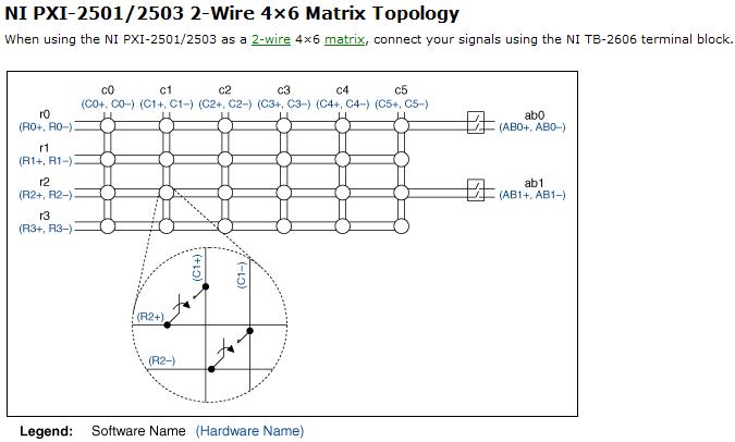
Resistance measurement using PXI2503
Hi, I am looking to understand how PXI-2503 measure resistance of 2-wire matrix 4 * 6.
and I tried several different configuration on my board but I couldn't receive the correct value of the resistance.
Software:
I use the example of LabView8.5 (niSwitch DMM Scanning.vi synchronous switching)
My scan list of entry (c0-> r0) under the switch
between 10000 and resolution 100 m under the DMM
Material:
I tried several set upward,
1. I put a resistor between C0 + AB0 + and r0 + AB0 -; and - c0, r0 - connect to GND, (this configuration gave me some graphics but no resistance)
2. I set the resistance between c0 +, r0 + and AB0 + (they connect) and c0,-r0, AB0 - (but it gives nothing.
my setup is bad? why I could not receive any resistance...
Thanks for any help
Hi Newer104,
The problem may be that the analog bus relay is not closed. Please refer to the following image and note that the ab0 relays must be closed to create a path between the rows/columns and the analog bus.
If I understand correctly, then I recommend placing the resistance between c0 + and c0 - and create the entry list of scan to the following address:
R0-> c0 & r0-> ab0;
Let me know if this solves your problem. Best regards!
Chad Erickson
Switch Product Support Engineer
NOR - USA
-
How to make your own Board BNC connector for 37 pins PCI-6010?
This is first time I am doing data acquisition and the BNC-2110 present can be connected to PCI-6010. How to make a Board for it?
I'm not sure what you mean by "some"; The BNC-2120 exposes all channels HAVE and AO on connector 0 of a standard feature of E, M or X series.
- Eight BNC connectors are for eight differential channels of I. For example, for the BNC connector labeled 'I 0', the Center connects to the 'I 0' pine and the outside connects to pin 'HAVE 8'. (The BNC-2120 probably would not be a good choice for someone who wanted to use the channels in unbalanced mode).
- Other two is for the analog output; the centres are ' AO 0' and 'AO 1' and transmissions are related to "AO GND".
- There is another connector BNC for PFI 0; all other PFI (with the exception of the 10, 11 and 15) are broken down as screw terminals.
- Other BNC connectors connect what either directly (the unit is powered by the + 5V line but otherwise works autonomously, and the "user defined signals' are connected to terminals to adjacent screws).
It seems like it wouldn't be difficult to have a cable that was going on a PCI-6010 the 37 pins on the connector 68 pins on the BNC-2120. I'm a little curious as to why we do not have one. Possible reasons off the top of my head which may explain why not:
- cards PFI/description would be a mistake (for example, on a series of E/M/X ' CTR 0 SRC "PFI 8; on the 6010 is PFI 0.)
- No digital lines (E/M/x series P0.0 P0.7 via are independent; on the P0.0 6010 P0.5 and P1.0 by P1.3 are shared with PFI lines)
- Confusion about being able to connect to other devices that we sell with connector d - SUB 37 pin, but who do not use a compatible pinout (for example, the PCI-6239, PCI-6510 or the NI 9237). Here again, a PCI-6703 also uses a 68 connector pins, but has a completely incompatible pinout as well.
But it seems that those who would be pretty easy to deal with, because it is useful to be able to connect to the BNC-2010. Maybe it's an idea for the Exchange of ideas information Acquisition?
Anyway, if you want to have pushed BNC for everything on your Board of homebrew will need you:
- 8 or 16 BNC connectors to HAVE, depending on whether you want single-ended or differential. For differential, the centres are GOT by AI 7 0, and transmissions are AI by AI 15 8. For asymmetric, the centres are HAVE 0 through 15 AI and transmissions should all connect to GND AI.
- HAVE a sense (I think that you only need this if you use channels Nonreferenced Single - Ended (NRSE). See also: noise considerations for analog signals and field wiring.)
- Two for AO (centers are AO 0 and 1 AO, outers times connect to AO GND).
- Ten for PFI/digital lines. Outers will connect to GND D.
Up to a maximum of 29. You want maybe less, depending on your application.
-
Cannot detect the limits of reverse front/market
I have problems with the switches front and rear for my stepper motor system. When I created a NI Softmotion axis in Labview, no matter how to set limit switches, either appear as assets or both inactive, regardless of the position of the platform. I use for my end of race, photointerrupters. When I don't have the equipment under voltage, the photointerrupters works as expected and give a signal of 0 V when the platform is not the limit and V 5 beeps when the platform is at the limit. But when I try to use the Labview interactive panel (or in a VI elsewhere too) the limits are not detected and behave differently as well. I got a voltmeter connected to see how the tension behaved and pressure readings are odd. In a case when I tested the 'active' signal of each switch, was one of the limit switches to 6.7 V and the other was at 3.7 V, even if they had the same exact wiring and configuration. I'm completely stumped on how to connect these in the system so that they work or how to configure Labview to properly recognize these limits (meaning sourcing vs shipwreck and active State power). I searched the forums and manuals, but I can't seem to find a solution. Here are more details on the system:
The engine is now a platform back and stepper motor is powered by a Kollmorgen P70530 stepper drive. To communicate between the command of stepper motors and the computer, I use a cRIO 9076 with a NI 9512 in the chassis. To connect the end of race in the system, I used the NI 9512 connection block 37 pins. Switch in the photo that I use is a strong GP1A05 CIPO Photointerrupter with connector. For this photointerrupter, there 3 pinout: a Vcc input (voltage source), a GND input and output Vout. The SCR is supposed to be connected to a source of 5V and GND to the mass (obviously) with resistance to pull-up between Vcc and Vout (I use a k 10 Ohm resistor as who has what has worked for me in the past with this specific photointerrupter). Vout is supposed to give a signal 5V, then the limit would be active and 0V when it is not active. How I had connected the photointerrupter to the connection block 37 pin was as follows: to the limit before, I had the VCC to pin 9 (+ 5V OUT), GND was on pin 3 (COM) and Vout was on pin 1 (before the deadline). For the inverse limit, I had the VCC to pin 9 (+ 5V OUT) GND was pine 24 (COM) and Vout was on pin 20 (inverse limit). I also tried to connect terminals GND the switch of the photo to the GND (shield) pin on the plate at terminals without success either. In regards to Labview, I am running Labview 2011 SP1 on my computer.
If you have any ideas, I would greatly appreciate it if you would share that I am really confused with something that seems on the surface to be quite banal.
Thank you
Steve
Steve:
I am puzzled too-
Manaual I looked:
http://www.NI.com/PDF/manuals/372153d.PDF
Your PIN seems correct.
I assume you have a power supply connect to Vsup and COM.
Research on page 3-10 for sourcing of the shows without pullup resistance, have you tried remove the 10Kohm?
But watching page A-3 for levels of limits, it shows<5V for="" low="" and="" 11-30v="" for="">
I'm confused-pg 3-10 looks like the 9512 provides its own pullup still pg A-3 show the necessary voltages for entries.
I hope someone can clarify this.
-AK2DM
-
Ground and the USB-8451-> it should reference?
I use a usb-8451 attached to a PCB card which has its own means with separate analog and digital designs. When I join the 8451 grounded strange results of power supply occur. Is it allowed to leave separate and unconnected?
Devices USB usually get their power supply (+ 5V and GND) of the device, they are connected. There is no need of additional connections to GND. These additional connections can lead to "mass loops" that can pick up noise and cause errors. -The 'front end' of a device properly designed USB is isolated from the power supply. If you connect anything to the input of the USB device, use the GND or NOT the entrance terminal, of reference and NEVER the Terminal GND of the Board that powers the USB device.
-
How to use HX85BA sensors with NI DAQ system?
Hello
I'm trying to connect two sensors of Omega HX85BA moisture to my NI DAQ system. The sensors detect moisture, barometric pressure, and temperature, using three 0 to 10 VDC positive outputs @ 10 mA or less, with a common thread of output. I have a SCXI-1000 chassis with two modules SCXI-1100 cards, 1102 b and a single 1102. Map of 1102 uses a block to connect SCXI-1303, while the other three cards use some 1300 years. The system will mainly use thermocouples for temperature measurements, but there will be other types of sensors, such as the two HX85BAs.
The manual of the product for the HX85BAs is not very clear on how to connect the sensor to the system. Terminal blocks each have 32 channels with the positive and the negative screw terminals, it doesn't connect three positive sensor outputs to individual channels, with the municipality of output connected to each channel? It will work installation with SCXI cards I have, or I will have to purchase different cards? The system will be expanded to include at least 4 cards in a separate chassis SCXI 1000 more, is not a problem for the purchase of different components to adapt to the HX85BAs.
Thanks in advance!
Hi BBalmforth,
You can connect the sensor to the SCXI-1100 1300 TB. Connect the positive output of CH + and CH - CHSGND. Common output wire must be connected to GND.
-
SMU 6341 and SCB-68: problem with several entries... * URGENT *.
Hello
I have an urgent problem, I would really appreciate help with.
I have a terminal block (SCB-68) connected to a multifunction data acquisition (6341). There are 4 entries in the Terminal:
1 sensor laser displacement, coming from a controller as a signal of analog voltage output ("1V" and "0V" on the controller). Connected to AI 0 and GND.
2. The accelerometer (PKI, coming from a then the voltage signal conditioner) connected to GND AI and AI 10.
3 load cells (PKI, coming from a then the voltage signal conditioner) connected to AI 11, 12, 13 and 14, each connected to the GND PIN is close.
Problem:
By MAX, if I read in 6 channels above my data acquisition (6341), my displacement sensor (#1) and the accelerometer (#2) behave very well. However, among the channels (AI 11 and AI 12) load cell switch in tension, as if they follow the movement sensor voltage (#1). For example, there is usually a mV - 800 in AI 11 voltage change.
This problem disappears when I'm not reading travel (HAVE 0, #1) laser. that is as soon as I remove this channel of my task, the readings of cell and accelerometer support back to normal (base voltage ~ 0V). Yet once if I ask again the laser channel, I see a vertical movement in the readings of load cell 2 (displacement varies with the current tension HAVE 0).
Attempts of fixation:
-tried to change the differential using AI laser sensor 0 and AI 9
-tried to delete the field of laser 120V Power
Any ideas at all would be greatly appreciated!
SCB-68:
http://sine.NI.com/NIPs/CDs/view/p/lang/en/NID/1180
SMU-6341:
http://sine.NI.com/NIPs/CDs/view/p/lang/en/NID/207415
This is the general idea. If you must use high impedance sources and that you have enough channels available, placing a channel of the grounding of entry between each other usually helps. You must analyze these chains grounded. Just grounded isn't them enough.
Example: Sensor has = AI0, ground = AI1, sensor B = AI2, ground = AI3, sensor C = AI4, AI5 = ground. Read AI0:5.
Lynn
-
If the pins GND and the VCC of the LS7411D and the LS7411N show connected to GND net and net SCR respectively?
When I go into properties, pins for these two items, those pins are not connected to any net.
Compare this to the 7404N, that displays automatically connected to VCC and GND nets. All 3 are on the enclosed drawing.
Hello
You must put a symbol of VCC and GND on the work area and it will automatically connect to the IC. In this example, the U1 and U2 are connected to the digital earth and VCC.
-
Question of the digital input USB-6009
Hello
I use USB-6009. I have problem in Input.I digital did not connect anything on all channels. But all of the DI/O channels generate 5 volts. And I tested the DI/operating system in the Test Panel also. All digital inputs are high. How I use it? Please suggest me the solution.
You're the one who said it was generating 5V. And I said that a fine should be detected as a logic one. Connect a gnd input.
When it starts, all of the default value of I/O at the entrances.
-
OR DAQ6009 with sensor and LabVIEW
I use the DAQ6009 OR and I try to attach a sensor sensitive resistant four to him. I placed a resistor in the circuit so the voltage divider rule is applied, but I'm not sure what channels to use? At the moment I have the 5Volts on the digital side connected to the probe and the resistance. I have the MASS of the digital connected to GND on the analog side channel and the other end of the wire fixed to Ai0 sensor resistance is this correct?
Help, please
Thank you
I'm afraid that I don't see your picture, I do not know if it attached correctly. However, I think that the reason why you don't see specific measures is that you make a measurement resistance with the DAQ assistant, but you should do a measurement of voltage.
The task you mention is not too difficult, just compare your signal to your threshold values by using the range of comparison (functions > programming > comparison of the block diagram) and then use the result of this causes a pop-up dialogue box (maybe using a case structure).
To draw the lines of two thresholds on your graph, you might just have another signal that is constant at the value of your threshold and output for the chart as an additional channel, you can have multiple signals on the same chart using the function of merging of signals.
Good luck
Kind regards
-
Premium vs potentiometer only finished reading
Hello
I want to read a potentiometer supplied with voltage the + 5V and GND signals from the DAQ card. I thought to connect output GND directly on the potentiometer and use single ended mode. Is there any point in using the differential mode in this case. If so, do I I just connect GND output directly to the entrance HAVE?
Thank you.
Simple nerve should work fine.
-AK2DM
-
reversal feeling engine movement MyDAQ
Hi, I need help with the following:
Detection time and the weft: sensor of the LDR (photocell) should be able to detect whether it is day and night (light or dark). During the day, if the Sun is so bright, special curtains should automatically shadow through the engine temperature sensors. During the night, curtains must be retrieved automatically. Note that the user has the ability to override decisions could make about deployment or recovering curtains.
I did a job on the vi program. However I don't know how to reverse the direction of the engine through labview. I'm controlling the speed of the motor using function (1 sample of Charron 1) freq counter DAQmx writing a command button. So I can't specify a negative cycle. Any suggestions?
My labview code is attached.
Use a relay of two bipolar directions connected to your daq dig out and the pilot and reverse the connection via the relay...
a real on the dig out will reverse the polarity
Note: realized that I had connected Daq GND to motor and... DO NOT CONNECT because of the reflex of induction coil of the motor, LSN has built in "flyback diode" for induction of relay coil.
Maybe you are looking for
-
PowerEdge R720 remove individual event
Hi everyone, our monitoring system (pulls that openmanage info) has a critical event on it, that I know is very well, she is treated. Now, I know I could erase the whole journal using the iDrac omconfig or, but I would rather just delete this unique
-
New C4580 to connect to the internet.
Hello I just bought and installed an HP C4580 on my mac. Anyone know of any way to be able to surf the net during printing? While on the web page that I want to print, I have to change my Internet networked printers. Any ideas would be popular. Thank
-
XPS 14 - Factory Reset - win 8
Hello I have a ultrabook of Windows 8 XPS 14 (L421X) - who doesn't have a CD/DVD optical drive. I have the restore disc (CD/DVD) that accompanies it. F2 / F12 does not give me an option of repair (only of the bios, diagnostics etc.). I want the syste
-
Question: Can I determine if my project is running in the SWF or HTML5?
HelloI created a project as the SWF and HTML5 to run on different computers based Office Windows.In the project, I want to identify if the project is running in SWF or HTML.I looked at the system variables and can see that he has cpInfoIsStandalone t
-
AeRender - "no model of rendering parameters were found.
Hello, iam using after effects CC as a network solution. IAM trying to make my project via the console and he already give back me my beautiful projects! But if I try to set a specific model of my project (RStemplate, OMtemplate), it won't work.aeren