Connecting channels with the PXI-2530 b
Tags: NI Products
Similar Questions
-
Variation of thermal EMF of the PXI-2530 modules
This message/question is a companion of my the most recent message in another thread.
In addition to watching some resistance higher than expected that affected current measurements using modules PXI-2530 multiplexer 4W topology, I saw systematic variation in track-to-track blood pressure measurements. Tensions would increase gradually through the 16 channels in a configuration by measuring the voltage at the terminals a resistor 1.5 kOhm with 0.5 au crossing (75 uV). I've identified that the thermal EMF of the reed in the PXI2530 module switches is on the same order of magnitude of these measures and set out to quantify the differences EMF thermal track-to-track between my three modules.
Test method: I have a TB-50 which is configured to mux the signals of tension for a DMM. I connected each of the four DB-50 one cable of 176 pins to this block and collected with a PXI-4071 pressure readings set to 7.5 digits precision in the range of 100 mV and > 10 GOhm impedance. For most channels, it took several minutes for the voltage stabilize - or at least appear that it was to stabilize.
I enclose three graphs. Note that the vertical scale is the same on each.
Data that triggered this survey was collected with MUX1, via connector P2 to voltage. The magnitude was not quite the same-probably related to the phenomenon of stabilization time, but obviously the worst group of channels three multiplexer modules.
The three modules were all bought at the same time (about 2 years ago), but had only limited its use in the first year or more. The three now have various 'mileage' based on my use. But MUX1 clearly behaves differently two other modules. The
I changed my test conditions to spend 0.5 au via a higher resistance to thermal EMF less important. The PXI-2530 sheets indicate that thermal EMF must be less than 50 uV. In most of my measurements, it is. But not for MUX1!
Any thoughts?
Thank you
Jeff
Hi Jeff,
You can check that all the three modules are PXI-2530, not PXI-2530 b (while, as the PXI-2530 b parts slightly higher thermal emf)?
Specification of emf thermal 50uV of the PXI-2530 is a typical value, is not a guarantee of spec. See a few channels higher than the spec is not a cause for alarm, but it shows that we must take account of this in our measurement error. Note that the industry standard for the technical measure thermal emf is to close the relay, wait a few minutes and then take a measure of tension. For example, if you scan through a switch faster than a relay per minute or so, the thermal emf will be less predictable and stable. A single module performs worse at these low voltages is not indicative that this module is a failure, etc. the module is fine. Unfortunately, the reed relays have more emf thermal relay of the armature, mainly because of the many layers of metal in a Reed compared to a frame (each metal junction is a source of emf if these metals are not the same).
Thermal EMF is proportional to the temperature, it may be interesting to note the position of the chassis of the less powerful module. Placing hottest modules (scanners, Ara, RF, etc.) will reduce the thermal emf.
-
Acquire more than 2047 samples with the PXI-4461 instaled in SMU-1073
Hi all, I would ask you for help with the buffer limit.
I intend to buy digitizer PXI-4461 and he instal in SMU-1073 chassis, namely control via MXI Express of Labview installed on a separate computer.
What I need:
-to acquire data of a single channel of AI, but at least a sequence of 20 kS by a acquire task, in some situations until 200kS by a task to acquire.
The question:
- I can gain more than 2047 samples in a single sequence, like 200kS, with the PXI-4461 installed in SMU-1073?
Internal buffer of the PXI-4461 is reserved to 2047 samples. So I'm not sure if Labview can download remotely via MXI Express the data in the buffer of the PXI-4461 via MXI Express fast enough without any affection of the sampling program.
-in the case, this PXI-4461 with SMU-1073 isn't the right combination, what chassis and a controller can do?
Thanks much for the reply
Jan
It will work for you.
The on-board buffer 2047-sample is used only as a backup if the flow of data to the PC host (via MXI Express in this case) is not fast enough... that it will be (explained below). DAQmx transfers data from the buffer of the device to the host PC as fast as he can and, in ideal conditions, should not save the buffer 2047 much at all.
Let's just say you get 110 MB/s (randomly from a MXI data sheet) flow on your MXI connection. The 4461 has 2 analog inputs, which will be at 24 bits, we just round 32-bit in case it transfers the data in this way.
4 bytes/sample (32 bit) x 200,000 s/s x 2 (channels) = 1.6 MB/s, which is well below the 110 MB/s, which will make the MXI link.
clear as mud?
Germano-
-
What do I have to remove the battery from my PC when I connect it with the cable?
So that the battery do not damaged.
What do I have to remove the battery from my PC when I connect it with the cable?
Tell me what I need to do for that battery not damagedHi mate,
Don t worry, just use your machine and leave your battery in your machine, because an electronic load look at your battery, so no damage will be caused.You know, technology is in fact at a good level and I think it s ok to operate your machine with cables and battery SET. :
Greetings
-
OR DC Soft Front Panel, minorbug, small bug with the PXI-4110
Hello
The NI DC Soft Front Panel V14.0, with the PXI-4110, scrolling to negative tension, works as expected to-10V, but then returns to 0. If we change from - 1V procedure, it goes...-8-9,-10, -1, -2... instead of-8-9,-10, -11, -12...
Everything about her, a simple thing that I miss is a switch for all three voltages.
(Also, IMO, it would be logical for negative tensions with the arrow pointing down, not more).
My 2 c
Hello Janaf,
I completely agree with two of your statements, I tabled a report of corrective measures that you can monitor in the next versions of DCPower to see if this is fixed with the FPS. CAR number: 512257
I've added notes that only manual insertion of numbers - less than 10 works and that it was not logical to use arrow increment or upward arrow to reduce the output voltage.
-
Pulse modulated CW with the PXI-5650 and PXI-6653
Hello
I'm trying to generate a signal CW of pulse modulated with the PXI-5650 as source RF and the PXI-6653 as the modulation signal. Basically, I'm trying to generate a simple radar waveform. It seems that it would be possible to use the synchronization Module (6653) to transform the RF output on / off on the signal generator (5650), but I do not know how to route the signals from one to another using LabView.
Has anyone tried this or something like this before? Can anyone please offer some advice?
Thank you!
-John
Hi John,.
Reading your post, it seems you want to use your calendar and map of synchronization to the RF output power, in other words, on Off Keying. OOK modulation is a feature built into the 5650. For more information, you can navigate through the NI RF Signal generators Help for devices-RF signal generators > NOR -> NOR 5650/5651/5652 overview-> Modes of Modulation and simply click on the Modulation Modes.
An example of this is found in the example Finder OR by navigating to the help-> find the examples in LabVIEW and then navigate in the Finder to example NOR material input and output-> Modular Instruments-> NI - RFSG-> signals-> RFSG 565 x Digital Modulation.vi.
Kind regards
Jason L.
-
Impossible to read 4 channels with the or 9234
Hey, I'm tasting 4 simultaneous channels to 51.2 kech / s rate for each channel with the NI 9234 module.
I use a callback function to read from the buffer.
I am accept to get to playback 4 channels of 51.2 k * 4 = 204.8 k s/s.
and I still recive data 51.2 kech / s.Need help, I don't know what's wrong with my code.
I enclose my hope of code it will help...
Thank you!

My installation information:
Material: NEITHER 9234
Version of Windows: XP
Language: Qt (C++)Hey simon27,
When you have installed DAQmx, did you also install text code support? There are several examples that should have installed with DAQmx which is very helpful in getting you started. "" "" "They can be found by going to your Start menu, then all programs" National Instruments "NOR-DAQ" NOR-DAQ "support textual Code ' ANSI C examples.
In case you do not installed the supported text based code, I have attached two examples which I think would be more useful to you. Try to run these examples and see if you get the same errors.
-Nathan H
-
connection Bluetooth with the mobile phone cannot be established
HP pavilion laptop g6 with windows 7.
connection Bluetooth with the mobile phone cannot be established, all drivers were dated until, when it is associated with my phone samsung smart, driver downloads and everything is ready for use.but when click the smart phone
It shows offline and it said no device ID is given,
What to do, please help
my portable BT device is defective? or some other problem, has also tried to connect other phones too, but same problem.
Rgds,
Hello
I just want if sure that you have the right driver installed from this first link provided in the answer from the Support Engineer. If you click this link, then clikc the first option 'Use the device in Windows 7 Troubleshoot utility' need you a paragraph with a link to the appropriate driver.I will link here just to make sure.It's the right driver you need. Please verify that this is the one that you have installed and do we know the results. -
Windows media center analysis drops channels with the call sign not in the guide
I'm trying to find the right place to report this problem.
When library scanned for channels recently that he hasn't found a bunch of DTT hd (clearqam) who are present and unencrypted.
Scanning with the help of the application of the tv tuner has revealed that the channel was present and unencrypted.
He showed that the channels have call signs which were not present in the digital guide. that is a call sign was "KPHO HD" when the digital guide for the channel list KPHODT
I had checked in the list of all channels that find the Media Center and the numbers were not present in media center.
This seems to be a bug because the channel should be found even if no digital guide for the channel is found.
The solution is to locate the actual channels by another application.
Add channels with the guides Add missing channels
Change the channel to have the correct list and the channel number.
Check out these links
TV on your computer: understanding and TV tuners TV signals:
http://windowshelp.Microsoft.com/Windows/en-us/help/aa79e7b4-E423-4459-ad22-1c240a8ffcd51033.mspxTV signals that are supported by Windows Media Center:
http://windowshelp.Microsoft.com/Windows/en-us/help/ef5b8360-958c-425B-9529-2922167e78631033.mspxThe transition to digital TV and Windows:
http://windowshelp.Microsoft.com/Windows/en-us/help/4d88063d-8842-42d2-B699-0fdce8249e531033.mspxSet up a TV signal in Windows Media Center:
http://windowshelp.Microsoft.com/Windows/en-us/help/589879da-b5a9-4E8F-b43c-c5eb99290e8d1033.mspx -
Extract and save all the channels of the PXI-5105 with 4 M of edge detection... Help!
Dear collegaues!
Please help me to improve my request, exhibit attached and sorry for my English.
So my task is to extract and save all the channels (eight) of the PXI-5105 with 4 M of detection of peaks and sample rate 4 M with loop 1 sec...
Entered all my channels are wiring detectors NaI with 0, 5... 1 microsec pulse (really) width and 0 kHz at not more than 40 kHz freq.
Why I chose the registration of 4 M and the sampling frequency of 4 M namely? Answer is that I tested previously PXI-5105 40 kHz generator and pulse width 0.5 microsec. It works great and detection of peaks indicate 40000 pulses/s for me. If I set lower than 4M record and sample rate of 4 M, it is without work. In my honest opinion record 4 M and the frequency of sampling of 4 M are parameters very min.
In the detection of peaks time present only 6 working channels... When I connected to diagram more 6 "detector.vi peak" - I see the error "...". out of memory... ».
Advise me please, what needs to be done to it, it's all working well.
-
What pins to use to receive the data from the PDS ELITE RS485 with the PXI-8431/2?
Hello!
I use the PXI-8431/2 to read data from the flow meter PDS ELITE (Modbus RTU). Receiving data, the RS485 protocol request to terminals 4 and 5, but this configuration does not seem to work. When I connect the RS-485 converter USB of Microflex I get the data correctly, so somehow between the PIN lay and PXI this problem there.
Can someone help me?
See you soon,.
Steven
Hello Steven,
I think that what was Hossein trying to send you is the following:
How to connect and configure a device with RS-485 2-wire
Can you also tell me a little more what you use to read the data? What environment. You have 2-wire or 4-wire Modbus RTU?
Kind regards
-
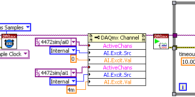
Configuration of the individual channels on the PXI-4472 b
Hi, I use the card PXI-4472 b to acquire data of vibration using sensors with different frequency ranges. The problem I have is that some of the transducers require being fed by the jury (via IEPE) and some don't and I can't find a way to turn the excitement on and off for individual channels, only each other.
I am using LabVIEW 8.6 and that you have configured all channels using the nodes property to activate the excitement and specify the current, but not all channels require that.
It says clearly in the data sheet of the map of 4472 channels are individually configurable for the IEPE, can someone please tell me how to proceed?
Thanks in advance,
Darren.
Howdy Darren,
Please see the following screenshot that illustrates how to set different values for different channels of IEPE all in a single task using DAQmx. The key point here is the property of ActiveChans. Otherwise, as you know, 3GEF55NQ knowledge base: How can I activate IEPE excitement on my DSA in DAQmx device? would do the trick.
I hope this helps!
-
Trip trying to rearm with the pxi-5122 times
Hi all!
This is my first discussion in this forum so I'm not sure this is the right place to post, because I'm using LabView, but maybe it's a hardware problem.Then... I have a problem to calculate the tripping time rearm to pxi 5122.
Compared to data sheets, I read that it should be about 3 us with the CDT to the large or 12 US if on.
But I need a precise measurement of the time out after each record measured so I decided to find it by myself...
With the help of an acquisition program that I have previous written in LabView, I started only acquisitions of 10000 records and each record is composed of 128 samples; as signal I've used waves square with different frequencies, 10 volts peak-to-peak (my trigger was set on the first channel of 5122 with 1 volt in value of edge).First acquisition: wave of 50 kHz. Theoretically, I s 0,2 need to capture 10000 records without losing all the square wave signals. Choose a time of acquisition for a single record of 15.3 us, I found that the time required is 0.199998 , very similar to the one expected.
Then by choosing a time of acquisition for a single record of 15.4 us, I found approximately 0.4 s.
I can guess that this latter one each tops of two waves will lost so I held twice the capture of 10000 records time.Because the wave is 20 us I calculated a timeout of 20-15, 3 = 4.7 us.
It wasn't like the 3 described us for the 5122 but I was not impressed and I went with my essay.Second wave: 20 kHz. I need 0.5 s to capture 10000 records without losing the square wave signals.
What I found was that in this case, choose us an acquisition time for one record of 39.6 required 0.5 s to capture all vertices, then with 39.7 us I held about 1 second, once again, twice by the time.
The previous example, I calculated the dead time: 50-39, 6 is 10.4 us.Very strange... idle time I'm supposed to be the trigger for rearmament (and thus fixed) did not differ in 2 cases.
Tried with other wavelengths, the values are always different.This also the frequency of the square wave of fixing and changing the number of samples per record.
For example, with 128 samples per files as I told before, I needed a measurement time of 15.3 US to collect all the consecutive summits, while 64 samples I need 12.8 us and so forth.So it seems to be a dependency between the dead after a record time (the trigger reset? now I'm not sure if I can call it that) and the sampling frequency of the pxi 5122.
But I don't know why, the acquisition of data behave in this way.Is this good? Rearm time should be set, shouldn't it?
I know it took some time to read my problem but I tried to be more precise, I could.
Thank you in advance.Giacomo
Yes that's correct. However, I do not think that its acceptable rate of the nearest synchronization that is chosen. I really think he goes to rate lowest according to acceptable timetable. So, if a synchronization rate is 2 and another is 5, and you want a 4.9uS rate, the synchronization will be 2, while 5 is the closest. (Or maybe it's the other way around) That's why you see the double period during the change of rates by just a fraction.
-
Problem with the PXI-6534 elimination change detection task
I ran into the following problem. I use a PXI-6534 and PXI-6602 with vb.net for detection with a timestamp of changes. My code works fine and I get data exactly as I want, the problem comes when I try to call the task.dispose function.
When I call him has, she throws an exception with error-200088 code, task does not exist. But the task is still stopped and I can run my code again and everything works fine. If I do not call the task.dispose, I get an error when I try to run my code again. The material seems to have left in an unknown state, and I have to restart my computer to get it back. (the MAX NOR even reset the 6602, he says only that the Council does not exist).
Interesting also is the exception thrown does not seem to be caught by the Try Catch method. The code traverses the Try Catch without any problem (step by step in the code anyway), but with the exception, the message box appears, either immediately or when coming out of the subroutine.
Also, I use TestStand 4.2 to call these functions, if that makes a difference.
Any help would be greatly appreciated! Its very frustrating that everything works and I get my data perfectly, but I can't run the code without exception popping up, and I can't seem to catch the exception.
Here is the code I use:
    Public Sub StartChangeDetect_UUT1()
        If myCDrunningTaskA Is Nothing Then
            Try
                ' Create the task
                uut1ChangeDetectTask = New Task()

                '************************ Create the digital input virtual channel alias
                'Assign ports to digital virtual channel
                uut1ChangeDetectTask.DIChannels.CreateChannel("Dev1/port0:3", "ChangeDetectUUT1", ChannelLineGrouping.OneChannelForAllLines)
                'uut1ChangeDetectTask.DIChannels.All.DigitalFilterEnable = True
                'uut1ChangeDetectTask.DIChannels.All.DigitalFilterMinimumPulseWidth = 0.000001
                uut1ChangeDetectTask.DIChannels.All.InvertLines = True
                uut1ChangeDetectTask.DIChannels.All.DataTransferMechanism = DIDataTransferMechanism.Dma

                'Assign ports to monitor for change detection, both rising and falling edges
                Dim rising As String
                Dim falling As String

                rising = "Dev1/port0:3"
                falling = "Dev1/port0:3"
                uut1ChangeDetectTask.Timing.ConfigureChangeDetection(rising, falling, SampleQuantityMode.ContinuousSamples, 4000000)

                'export change detect event to PXI backplane so we can get timestamps from timer.
                uut1ChangeDetectTask.ExportSignals.ChangeDetectionEventOutputTerminal = "/Dev1/PXI_Trig0"
                uut1ChangeDetectTask.ExportSignals.ChangeDetectionEventPulsePolarity = ChangeDetectionEventPulsePolarity.ActiveHigh

                'uut1ChangeDetectTask.Stream.Timeout = 20000

                ' Verify the Task
                uut1ChangeDetectTask.Control(TaskAction.Verify)

                ' Set up the data table
                Initializeuut1DataTable()

                ' Create the readers for the DI and the CI
                uut1ChangeDetectReader = New DigitalSingleChannelReader(uut1ChangeDetectTask.Stream)

                uut1CDCallback = New AsyncCallback(AddressOf uut1ChangeDetectCallback)
                uut1ChangeDetectReader.SynchronizeCallbacks = False
                ' Set up our first callback

                uut1ChangeDetectReader.BeginReadMultiSamplePortUInt32(-1, uut1CDCallback, uut1ChangeDetectTask)
                myCDrunningTaskA = uut1ChangeDetectTask

                'Set up Timer for time stamp

                uut1TimeStampTask = New Task()
                '****************set up PXI-6602 timer to get buffered change events.  ie capture timer output on  the PXI_Trig0
                'we can then correlate this timer capture buffer to the change detect buffer to get the time stamps

                uut1TimeStampTask.CIChannels.CreatePeriodChannel("Dev5/ctr0", "TimeStamp1", 0.0000001, 0.02, CIPeriodStartingEdge.Rising _
                             , CIPeriodMeasurementMethod.LowFrequencyOneCounter, 4, 4, CIPeriodUnits.Seconds)
                uut1TimeStampTask.CIChannels.All.CounterTimebaseRate = 20000000.0

                'Use exported change detect from 6534 board to take counter sample
                uut1TimeStampTask.Timing.ConfigureImplicit(SampleQuantityMode.ContinuousSamples)
                uut1TimeStampTask.CIChannels.All.PeriodTerminal = "/Dev5/PXI_trig0"
                'uut1TimeStampTask.CIChannels.All.DuplicateCountPrevention = False
                uut1TimeStampTask.CIChannels.All.DataTransferMechanism = CIDataTransferMechanism.Dma

                ' Set timeout
                'uut1TimeStampTask.Stream.Timeout = 20000
                ' Verify the Task
                uut1TimeStampTask.Control(TaskAction.Verify)
                uut1TimeStampReader = New CounterReader(uut1TimeStampTask.Stream)
                uut1TSCallback = New AsyncCallback(AddressOf uut1TimeStampCallback)

                uut1TimeStampReader.SynchronizeCallbacks = False
                uut1TimeStampReader.BeginReadMultiSampleDouble(-1, uut1TSCallback, uut1TimeStampTask)
                myTSrunningTaskA = uut1TimeStampTask

            Catch exception As DaqException
                ' Display Errors
                MessageBox.Show(exception.Message)
                uut1StopChangeDetection("C:\PT3771\TestResults\")
            End Try
        End If
    End Sub

    Private Sub uut1ChangeDetectCallback(ByVal result As IAsyncResult)
        Try
            'If runningTask Is ar.AsyncState Then
            If myCDrunningTaskA Is uut1ChangeDetectTask Then
                ' Read the available data from the channels
                Dim data As UInt32() = uut1ChangeDetectReader.EndReadMultiSamplePortUInt32(result)

                Dim b As UInt32
                For Each b In data
                    ' in TestData waveform Y axix is data, x axis is time

                    uut1TestData.SetY(uut1ChangeDataIndex, b)
                    uut1ChangeDataIndex += 1

                Next b

                '' Set up a new callback
                uut1ChangeDetectReader.BeginReadMultiSamplePortUInt32(-1, uut1CDCallback, uut1ChangeDetectTask)
            End If
        Catch exception As DaqException
            ' Display Errors
            MessageBox.Show(exception.Message)
            uut1StopChangeDetection("C:\PT3771\TestResults\")
        End Try
    End Sub 'DigitalCallback

    Private Sub uut1TimeStampCallback(ByVal result As IAsyncResult)
        Try
            'If runningTask Is ar.AsyncState Then
            If myTSrunningTaskA Is uut1TimeStampTask Then
                ' Read the available data from the channels
                Dim data2 As Double() = uut1TimeStampReader.EndReadMultiSampleDouble(result)

                ' in TestData waveform Y axix is data, x axis is time
                Dim b As Double
                For Each b In data2
                    uut1TimeSum = uut1TimeSum + b
                    uut1TestData.SetX(uut1TimeStampIndex, uut1TimeSum)
                    uut1TimeStampIndex += 1
                Next b

                ' Set up a new callback
                uut1TimeStampReader.BeginReadMultiSampleDouble(-1, uut1TSCallback, uut1TimeStampReader)

            End If
        Catch exception As DaqException
            ' Display Errors
            MessageBox.Show(exception.Message)
            uut1StopChangeDetection("C:\PT3771\TestResults\")
        End Try
    End Sub 'CounterCallback

    Public Sub uut1StopChangeDetection(ByVal location As String)

        Try
            If Not (myTSrunningTaskA Is Nothing) Then
                uut1TimeStampTask.Dispose()
                myTSrunningTaskA = Nothing

            End If

            If Not (myCDrunningTaskA Is Nothing) Then
                uut1ChangeDetectTask.Dispose()
                myCDrunningTaskA = Nothing

            End If
        Catch ex As Exception
            MessageBox.Show(ex.Message)
        End Try

        uut1TestData.UpdatePointCount()
        uut1TestData.SaveToDisk("C:\PT3771\TestResults\uut1TestWaveFile.csv")
        uut1TestData.SaveToDiskBinary("C:\PT3771\TestResults\uut1TestWaveFile")
    End Sub 'StopTask
Joe,
Last updated. It seems that when the task.dispose is run, recalls seem to have called one last time. I took the call to the stopUUT1ChangeDetect in the two recalls (so eliminate it would not enforce a second time), and no exception was thrown.
Thanks for your help! Although if you'd still answer my question on the PXI-6534 Digital input filtering, I'd appreciate it.
Thanks again.
Thad
-
PXI-8115 controller incompatible with the PXI-1050 chassis?
I replaced two XP based PXI controllers with two controllers, PXI-8115 with WIN7 installed on them. System #1 has combined PXI-1010 chassis and System #2 has a combo chassis PXI-1050 chassis. The two 8115 controllers work correctly when it is installed in the #1 system (chassis 1010) do not produce but no video output when it is installed in the #2 system (chassis 1050). I use the same monitor on both systems, as well as the same adapter DisplayPort to VGA supplied with controllers. This suggests some kind of incompatibility between the 8115 and the 1050, but I can't believe I'm the first to connect a 8115 a 1050. Everyone knows about this problem? Y at - it solution or workaround? Is there something I forgot?
Thank you
PMAC
OK, I found a solution but I still don't know why it is the solution.
Each controller had a "Bizlink" adapter DisplayPort to VGA bundled with it. Of course, I tried two adapters with the same results on both systems. I tried a "Startech" DP to VGA that is used elsewhere in the installation and the system worked well. Why a brand different adapter works is quite confusing.
For anyone else having this problem try Startech manufacturer DP2VGA.
PMAC
Maybe you are looking for
-
What happened two or three times before each update others. The problem seems to correct itself on the next update.
-
I have a 2010 iMac that runs on OS X Lion 10.7.5. Can I pass safely lion in El Capitan?
-
Links on safari and some apps couldn't be turned on after I have updated to iOS 9.3 3 on my iPhone 6 s.
-
Strange message appears when searching for the search bar
This happens whenever I search from the search bar... I type a few words into the search bar and press ENTER. Then a small dialog box (subtitled "Application Javascript") appears, displaying a short message: shows "research #2", as the attached pictu
-
OfficeJet Pro 8600 N911a: How can I determine which cartridge needs to be replaced?
I installed an update to Windows Pro 10. Now, I can't say what ink cartridges need to be replaced. What happened to the apps that gave me the ink level?