Construction of a simulation - Labview Robotics
My main points:
1. is it possible to generate an XML (like the one used for robotics simulation environments) using labview?
2. If so, it would be possible to then update this map dynamically with the data from the sensor (so if we find a wall we add it to the simulation where we believe it is)?
3. in the case, is there a low-no budget program that could create a card with the data that is also compatible with labview. (little a long ball, I realize)
I have alternatives, but this seems to be the most visually impressive. I would be grateful of any shed light on the subject.
Hello
LabVIEW Robotics module simplifies many things with regard to the implementation of your environments and projects designed by owner. To create an XML file from your own custom Setup program, you can use the LabVIEW Project Assistant start-up as described in Chapter 5 of this paper:http://www.ni.com/white-paper/14133/en/
You can update the environment dynamically without needing to edit XMLs as dedicated property nodes have received almost all the necessary options for the majority of applications. If you do not need to modify the XML code, it is possible to do either with the XMLSchema direct string manipulation toolkit (as xml files are simple markup text files). That being said, the manifest file is usually loaded before the main loop in the simulations of Robotics that did not trigger a dynamic update on the environment.
Tags: NI Software
Similar Questions
-
I recently started work on DaNI 1.0 Act LabView Robotics Hands-it is available in the Robotics 101 Resource Kit.
I'm stuck at step 11 of exercise 2: Introduction to the LabView environment development.
It says select Bitfile and navigate to this path. Can I'm lost and I was wondering how to get there.
Any help would be greatly appreciated.
Hi Ali,
I'm sorry for the No.
My problem is: I can't find the bitfile in my as project file.
After a lot of research (I did a complete search of the C:\ drive), I found an identical to the bitfile bitfile said in the tutorial.
I find the bitfile in this way:
Discovering Instruments > LabVIEW2010 > examples > Robotics > Starter Kit > Starter Kit roaming > FPGA Bitfiles > StarterKitRoamin_FPGATarget_StarterKitFPGAVI_E8A41200.lvbitx.
I'm using LabVIEW Robotics 2011 Module.
-
Multisim co-simulation / LabVIEW
Is it possible to add contacts from two States to Multisim and control of Boolean way to LabVIEW?
the attached example schema
-
Hello, I write because I can't launch the ecg Simulator that I downloaded from http://zone.ni.com/devzone/cda/epd/p/id/6189#0requirements
When I try to use it, it pops up a dialog box that says "find the VI named 'Configuration series Port.vi'. I tried to open the VISA set up series Port.vi, but I think that this number and the type of the entry and exit of it, does not match the expected by the program.
I would be grateful if you could send me the help.
Thanks in advance
I have a simulator for ECG. It is not made by me, but NEITHER
How to install
(1) leave Labview
(2) unzip to folder ...\National Instruments\LabVIEW 8.6\user.lib\_express (find you it in the folder program files)
3) started with Labview
(4) Se the image for help on how to find it
-
'Multiplication' of the Labview Robotics Starter Kit?
Hello! Im working on the odometry for my Starter Kit (model 4 wheels) based on the book "where I am? -You can download the book for free here: http://www-personal.umich.edu/~johannb/position.htm page 20 this theory says that the factor which translates as the number of pulses to linear distance is: Cm = D: PI * D /(n*Ce) diameter of the wheel (mm) = 4 "= 0,1016 mm n = gear ratio =? This linear encoder resolution (PPR) = 400 PPR so = distance = Cm * N_pulses Im not sure how I could calculate the gear ratio of the LR Starter Kit, taking into account that there are 4 speeds interconected for each pair of wheels. I found in a document from the COMPENSATION Commission that the ratio of the Starter Kit is 83:1, but if I try n = 83 distances Don t make any sense! -UNIC course laboratory 2 (PDF, 1 page assignment): "" "gear ratio: it's the amount of turns, it takes the engine to fill per 1 rotation of the wheel.» The ratio of the daNI robotic platform is about 83:1. (This value takes the engine reduction account) "" "" If anyone has the gear ratio calculated beforehand, or can give me some guidance on how to calculate it (or tell me if Im doing anything worng with units!), could you help me, please?
Mosadioluwa,
I do not know whence the value of 83:1, but I can tell you that the wheels of Starter Kit 1.0 have a gear ratio of exactly 2 Motors per wheel turn. The engine is mounted on a wheel of 40 teeth, which meshes with the 80 teeth gears that are mounted on wheels. This means that the ratio is 2:1. Note that the Starter Kit 2.0 has a 1:1 ratio.
Chris M
-
I installed the Labview Robotics module for evaluation, but when I start now Labview I meet the following start screen:
How to bring back the Labview standard splash screen?
Terje,
When LabVIEW Robotics is installed, it replaces the file LabVIEW get a window on the way. You can return to the standard window began to to repairing the installation of LabVIEW:
- Go to add/remove programs from the control panel.
- National Instruments -click and select Change/Remove.
- Choosing to fix LabVIEW.
- Insert the LabVIEW Setup disk if you have an or navigate to the network location that you used to install LabVIEW.
- After you have repaired LabVIEW, you should be able to restart with the default value getting started window restored.
-
The USRP CSD requires the LabVIEW Communications?
I recently installed LabVIEW 2013 on my machine, as well as a whole bunch of toolboxes:
LabVIEW English 2013
VI Package Manager
Module LabVIEW Control Design and Simulation 2013
2013 LabVIEW Datalogging and Supervisory Control Module
2013 LabVIEW MathScript RT Module
NI LabVIEW 2013 LEGO (R) MINDSTORMS (R) NXT Module (in English)
Module OR Vision Development 2013
Module LabVIEW FPGA of 2013 (English)
Xilinx toolchain 14.4
Module time real LabVIEW 2013 (English)
2013 LabVIEW Touch Panel module
2013 LabVIEW Robotics module
Software OR SignalExpress 2013
LabVIEW Sound and Vibration Measurement Suite 2013
Module LabVIEW Statechart of the 2013
LabVIEW 2013 for myRIO Module
Toolkit OR run real time Trace 2013
2013 LabVIEW System Identification Toolkit
LabVIEW Toolkit 2013 Digital Filter Design
4.3.4 for LabVIEW Modulation Toolkit
2013 LabVIEW VI Analyzer Toolkit
2013 LabVIEW Database Connectivity Toolkit
2013 LabVIEW Report Generation Toolkit for Microsoft Office
LabVIEW Spectral Measurements Toolkit 2.6.4
2013 LabVIEW Advanced signal processing Toolkit
LabVIEW 2013 PID and Fuzzy Logic Toolkit
Kit filter LabVIEW Adaptive, 2013
Toolkit LabVIEW DataFinder of the 2013
2013 LabVIEW Desktop Execution Trace Toolkit
LabVIEW 2013 Multicore analysis and matrices hollow Toolkit
LabVIEW 2013 power electric Suite
Toolkit LabVIEW 2013 GPU analysis
Biomedical Toolkit LabVIEW 2013
Module LabVIEW 2013 OR SoftMotion
NEITHER Motion Assistant 2013
NEITHER Vision Builder for Automated Inspection 2012 SP1
OR DIAdem Professional 2012 SP1 (English)
LabWindows/CVI 2013 development system
Module time real LabWindows/CVI 2013
LabWindows/CVI Spectral Measurements Toolkit 2.6.4
Spectral measures of LabWindows/CVI DURATION 2.6.4
LabWindows/CVI SQL Toolkit 2.2
Toolkit for processing Signal of LabWindows/CVI 7.0.2
LabWindows/CVI PID Control Toolkit 2.1
Execution of LabWindows/CVI Profiler 1.0
Measurement Studio Enterprise Edition for Visual Studio 2012 2013
General safety NI Patch 2nd quarter of 2013
NEITHER TestStand 2013
NEITHER ELVISmx 4.5
NOR-DAQmx 9.7.5
Xilinx 10.1 Compilation tools (requires the build tools additional Xilinx DVD)
Device drivers or - February 2013I tried to follow this tutorial with the USRP 2932, coming soon, but I found out later that I have seem to have none of the LabVIEW Communications. No not those who prevent me from using the USRP radio? If not, then is there any restrictions on what I can do with the radio without communication?
Hi BreadLB,
The link to the tutorial you posted is based on LabVIEW Communications System Design Suite, a new software environment designed to accelerate the prototyping of the algorithm and stable air. It is a completely separate and independent of LabVIEW environment. See my post here for more details. You can also download a free 30 day trial copy here. Your hardware is supported with LabVIEW and LabVIEW Communications.
The 2932 NOR is a network based USRP, and there a small on-board FPGA. For this reason, the FPGA on that specific product is not a target of LabVIEW FPGA. The NI 294 x / 5 x family has a large Kintex 7 FPGA and can be programmed using LabVIEW FPGA and LabVIEW Communications, as in the tutorial you posted. The 2932 OR can be used with your host PC and LabVIEW for a variety of applications. Unfortunately the tutorial that you have linked to your post requires the NI 294 x / 5 x hardware and Communications of LabVIEW. If you have questions about a specific application for your 2932, please post more details and we would be happy to help you.
-
Trace of the end effector of a manipulator Robot in Simulator 3D display
Hi all
I am currently working on a project to control robot on LabVIEW Robotics Module 2013.
In project, I need to show 3D track of the Effector(or an arbitrary point of the last link) in the display of the Simulator.
So so we can easily see the error of monitoring (the diffrerance between the desired trajectory and actual path) on the façade of the Simulator.
I also added a picture of my primitive system to clarify what I needed.
Thank you.
Your photo, it seems that you already have a 3D scene called Simulator display. Is this VI an example that was provided to you? Or have you written this VI?
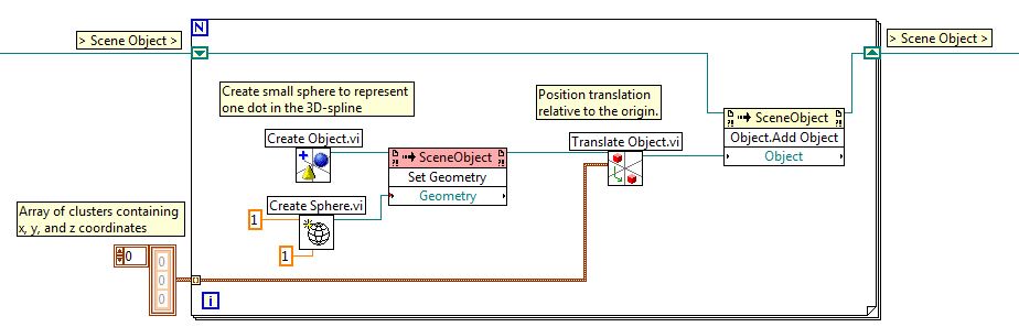
This isn't something I've done before, but assuming that the item titled display Simulator is a 3D scene or a 3D image, you could follow the path of the Effector keeping the Effector 3D locations in a wide range of groups, each with an x, y and z location. 3D scenes/images are used to represent physical objects in a virtual environment, so each location to which you want to trace would become an object. Below is an excerpt where I created a for loop that will create small spheres for each point that is stored in an array of clusters. These spheres are created, moved to the right and then added to the existing 3D scene location.
Your application may be different from what I proposed, but you should start by looking at the example of solar system set out below. This example shows how objects are created, added to scenes and interacts with.
Community: solar system with 3D picture control
-
Hi all
I allowed for students to install the version of LABVIEW. I'm new to the LabVIEW.
I installed license Toolkit LabVIEW Digital Filter Design in my laptop. But I can't find the options of digital filter in treatment of the signal from the controls palette. Its not there despite the installation. I checked in the license OR Manager he said toolkit Digital filter design has been enabled for this computer.
Can someone please help locate specific digital filter of this Toolbox options? How can I check the functions in the range control to the Toolbox, I installed?Thank you
IHAVE license fot the following content:
LabVIEW Student development environment
LabVIEW Toolkit for LEGO MINDSTORMS NXT
(Installed) LabVIEW Control Design and Simulation Module
LabVIEW MathScript RT module
LabVIEW System Identification Toolkit
Toolkit LabVIEW Digital Filter Design (installed)
LabVIEW Modulation Toolkit
LabVIEW SignalExpress
Module OR Vision Development
NEITHER Vision Acquisition Software
OR DIAdem Student Edition (installed)
(Installed) NI LabVIEW Real-time module
OR LabVIEW FPGA Module (installed)
LabVIEW database and control Module
LabVIEW Mobile module
LabVIEW PID and Fuzzy Logic Toolkit
LabVIEW Robotics module
LabvIEW Simulation Interface Toolkit
LabVIEW SoftMotion
LabVIEW Statechart Module
Motion Control and Motion AssistantHello
LabVIEW 2014 32-bit, he will find-> design of digital filters signal processing.
In Labview 2014 64-bit, I can find it or the other. I know that some tools are not supported in LV 64-bit. I couldn't find documentation on the system requirements for this toolkit so I could not say it, maybe you can change at LV 32 bits?
Good luck
Danielle
-
Unable to connect to starter kit 2.0 Robotics
Hi all
I know this question has been askedmultiple times, and I read trough forum messages, but cannot find a solution.
When I try to run a robotics project on DaNI, 2.0 Starter kit, I get a message of conflict resolution, saying "unable to connect to the target. --> See image rasthaus
I installed the latest version of labview, robotics, FPGA modules and in real time as well as pilots of RIO.
Once I disabled my firewall, I was able to detect the robot with MAX, but I was not even able to connect using labview.
Thanks for any help,
MortZxD
Hello
I had the same IP address as illustrated by MAX in my library of projects, but I could not always connect.
I reset the IP address of the robot to start in safe mode and changing an address IP static, dynamic and who did the tour!

Thnks
-
Hello
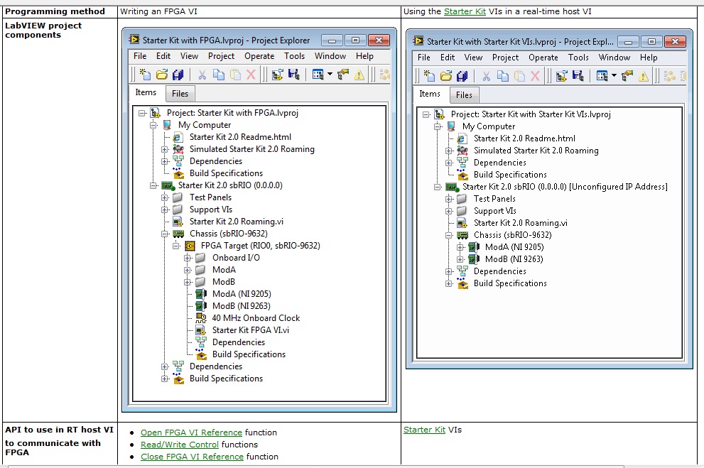
I have Robotics starter kit 1.0 and Labview 2012. I would use custimizing FPGA, which does not directly use the starter kit of screws. I haven´t have been able to find an example of this for the starter kit 1.0 and I don't ' want to start from scratch.
To clarify my question, I would like to work in an environment similar to the one on the left, instead of one that is indicated on the right but for the starter kit 1.0
So my question is, where can find an example of the itinerant program for the starter kit 1.0, with an FPGA vi?
Thank you
Juan
Certainly, as it is said "jordankuehn", what you see on the left of the image is a project, which added a FPGA target (right-click on the chassis > New > target FPGA), which allows to work in FPGA environment and not mode SCAN Engine (illustration right). Now unfortunately the 2012 version of LabVIEW and LabVIEW Robotics Module 2012 does NOT include an example to customize the work with the Starter Kit 1.0, unlike an example of work with the Starter Kit 2.0.
You could do the following: the version of LabVIEW 2010, if it had an example in order to customize the features of the Starter Kit 1.0, then you can install the 2010 version of LabVIEW and LabVIEW Robotics and get this example. Or you can see the attachment that is an example, I used to work with the Starter Kit 1.0 in 2012 of LabVIEW.
-
Robotics module vs «Tools for code import existing C/c++»
Hello
The descritption of LabVIEW Robotics Module has this line:
"Tools for importing existing code in C/C++ and VHDL.
Is this something new in the Toolbox, or is - this referring to the standard function available in the basic package?
I wasn't able to find special functions in the Robotics module. I missed something?
http://sine.NI.com/NIPs/CDs/view/p/lang/en/NID/209856#productlisting
Hello Andy,
As you said, import of existing C/C++ code is originally from LabVIEW, while VHDL is enabled via the LabVIEW FPGA module.
I checked with a few colleagues and it seems that this statement in the overview is just there to remind that the integration of the text based code should be simple and intuitive with our framework. I don't think there are new features in the Robotics module that will expand the capabilities.
-Daniel
-
How to integrate model of custom device controller
Hello
I now live a labview including 18 sub controller model, and I am trying to run this controller on RTOS VxWorks, through customized device model.
1. when I tried to run a model simple controller (ex, a controller with 3 ~ 4 void / screw) on RTOS VxWorks, I just put simple controller in
RT Driver.vi model, and then the build and deployment succeeded. 2. then, I did it with my model of labview in the same way above controller, but I couldn't even build my model controller labview. I don't know why, but the build process stops at the initialization stage. I think that this problem will appear when there are more than 3 ~ 4 sub vis are added under the custom device project.
Any ways to use a model of controller labview instead of just put a model in
RT Driver.vi? Now, I managed to build my model labivew, I saw the light of the compactRIO blinked, which measn the connection is ok by CAN - Bus.
But it's still weird and not possible to build my model at a time. In addition, cannot again build the custom devcie just before successfully built after the addition of two functions simply.
In any case, the solution to my problem is as below.
For example, my cruise controller written in labview consists of 3 simulation systems arrive.
Each system to arrive includes several subsystems.
First, create the model after adding one of 3 major subsystems. (In this case, I never had errors in the construction of models of labview)
Secondly, if the first step is ok, add one of the other 2 systems come in the custom device and then build again.
Thirdly, add the remaining subsystem in the custom device and establish the entire model and deploy it to the target.
With three steps above, I can still build devices customized successfully.
-
3D photo restores do not properly since the upgrade
I developed an application in labview 2012 and have recently updated until 2014.
Since this upgrade, I have a problem with my 3d image rendered incorrectly.
I am attaching the images as it is difficult to describe the problem. There should be 4 of robot arm placed on the corners of a gray box that is placed slightly above the ground. The image with the removed soil that shows the best, but it is obviously incorrect. Remove objects and textures can give better results in some respects, but the question is always present whenever I changed something.
It seems that parts of models are not rendered or sections are not rendered in the correct order, but I'm not aware of all the properties change this.
I tried to change the clip plain but documentation is very limited and I doubt that's the problem anyway as the middle of the image which is incorrect, the floor and the ends of the robots never seem to cut.
I am running Labview Robotics 2014 and using the Robotics Toolbox to generate arms on Windows 7 64 bit with nvidea GeForce GTX 760 graphics card.
Any help is appreciated.
Thank you
Nick
I experienced similar problems with the rendering window. I feel quite informal and subjective, it is that the render window is something that NEITHER is not updated with the latest improvements in graphics cards, and having developers use real 3D image controls instead.
I experimentally tested the 3D picture control and I can't see any advantage of the render window of performance compared to the 3D so image my, yet unofficial, impression is that image 3D controls are hardware accelerated now but it is not clearly stated in the documentation for LabVIEW.
You can put a window on a façade of VI 3D and select in the context menu 'Fit control component' and create a window similar to the rendering window. It requires a little more programming, but you get a lot more flexibility for your application.
If you are interested, join the Group Vision 3D!
-
Using NI 9870 with drivers of the robotic Module
Hi all
I am using quite a few sensors that are supported by the LabVIEW Robotics module (GPS, MIO, compass and probably a LIDAR soon.) However, I would really like to be able to use the module series OR 9870 RS - 232 in a CompactRIO to interface with these devices (currently they are connected directly to a PC.) Unfortunately, I do not know if there is a way to do it without having to rewrite the drivers for the FPGA. Someone has encountered this before or maybe knows a way I can do this without reinventing the wheel? Thank you!
Brandon
BrandonGT,
Worked on a similar problem. Take a look at this example . Note how the service contact numbers is used to add an identifier to the data before it is put into a common FIFO.
Maybe you are looking for
-
Qosmio X 300 - 14U - can't find not all USB devices
My Qosmio X 300 - 14U can't find my USB Kingstone Datatraveller, Storejet. Any help please.
-
I need to access my computer without the Administive password?
I want to what I can do to get into my computer if I don't have the password, administrative.
-
Recover the use of memory (WCF function)
Hoped one of the officiando on this forum could enlighten me on what I could possibly hurt. I created a WCF dashboard that shows a VMs CPU and memory Avg and Max using for the last 30 days. Data vFogkight in the dash of my review of the virtual machi
-
missing metric collections officer for the duration of downtime
Hello We had to stop the FMS, and after we grew up, we discovered that metric collections officer for the duration of the downtime was missing and not populated dashboard FMS, We have a hypothesis, that when FMS is down or not accessible by FGLAM on
-
Plans photography CC said I have 3 days before it stops working
I have a photograph CC Plan supported by Amazon. I just started my second year. When I start the PS, it gives me the warning about the imminent loss of the PS due to a problem with the payment to the account. The warning give me a link to manage my a