Multisim co-simulation / LabVIEW
Is it possible to add contacts from two States to Multisim and control of Boolean way to LabVIEW?
the attached example schema
Tags: NI Software
Similar Questions
-
NI Elvis and Multisim interactive without labview
If a circuit is implemented and tested with the help of Elvis, the results of an output displayed in Multisim and Labview? If I want to change my Multisim simulation to match the output of the circuit set up as Elvis, is possible in real time? I know that TINA can do with their hardware/software. Thank you
jweaver-
You can display the measurements in Multisim and LabVIEW. With NI ELVIS, you can use 12 instruments of autonomous software by installing the driver (FGEN, Noculars, DMM, ect). The instruments are built using LabVIEW. You can access these same instruments in Multisim environment and compare the Multisim circuit simulation commensurate with live material in real time. I included a tutorial describing how to do it using equipment OR myDAQ. The steps are the same for NI ELVIS.
If you want to create a custom beyond the 12 instruments application, you can program the instruments in the LabVIEW programming environment.
" Use myDAQ with NI Multisim Circuit Design software
-
Parallel FPGA in LabVIEW/Multisim co-simulation
Hi guys, it is possible to put 3 or 4 FPGA modules in a model of LabVIEW and then simulate jointly with Multisim runs 1 model plant? I want to simulate a converter of solar by using multiple parallel FPGA (this part on LabVIEW) cores conducted multiple interacting with the grid inverter bridges (this part is the Multisim factory model).
Hey hacmachdien,
This should be possible. If you have the Control Design and Simulation toolkit, you can use the control and the Simulation loop to simulate jointly with Multisim after you have installed the co-simulation plugin that comes with Multisim. See here for more information.
If you encapsulate your LabVIEW FPGA logic inside a Subvi, you should be able to use these subVIs in control and the loop simulation. There are a few caveats with this. First of all, the rate for the LabVIEW FPGA SubVIs must be configured depending on how they will run in the actual hardware. For example if the Subvi is inside a timed Cycle simple loop that is configured for a 40 MHz clock, you will need to configure the delay for the Subvi 25 ns. You can set up the period right-click on a Subvi in control and Simulation loop, then go to the Subvi node installation. In this menu, you can set the type of operation to be discreet and then configure the discreet calendar. Another restriction is certain things will not be supported as I/O. You can usually work around this by leaving your IO on the next level of your app and just by passing the values in the Subvi through controls and indicators. Let us know if you have any other questions!
-
Construction of a simulation - Labview Robotics
My main points:
1. is it possible to generate an XML (like the one used for robotics simulation environments) using labview?
2. If so, it would be possible to then update this map dynamically with the data from the sensor (so if we find a wall we add it to the simulation where we believe it is)?
3. in the case, is there a low-no budget program that could create a card with the data that is also compatible with labview. (little a long ball, I realize)
I have alternatives, but this seems to be the most visually impressive. I would be grateful of any shed light on the subject.
Hello
LabVIEW Robotics module simplifies many things with regard to the implementation of your environments and projects designed by owner. To create an XML file from your own custom Setup program, you can use the LabVIEW Project Assistant start-up as described in Chapter 5 of this paper:http://www.ni.com/white-paper/14133/en/
You can update the environment dynamically without needing to edit XMLs as dedicated property nodes have received almost all the necessary options for the majority of applications. If you do not need to modify the XML code, it is possible to do either with the XMLSchema direct string manipulation toolkit (as xml files are simple markup text files). That being said, the manifest file is usually loaded before the main loop in the simulations of Robotics that did not trigger a dynamic update on the environment.
-
Hello, I write because I can't launch the ecg Simulator that I downloaded from http://zone.ni.com/devzone/cda/epd/p/id/6189#0requirements
When I try to use it, it pops up a dialog box that says "find the VI named 'Configuration series Port.vi'. I tried to open the VISA set up series Port.vi, but I think that this number and the type of the entry and exit of it, does not match the expected by the program.
I would be grateful if you could send me the help.
Thanks in advance
I have a simulator for ECG. It is not made by me, but NEITHER
How to install
(1) leave Labview
(2) unzip to folder ...\National Instruments\LabVIEW 8.6\user.lib\_express (find you it in the folder program files)
3) started with Labview
(4) Se the image for help on how to find it
-
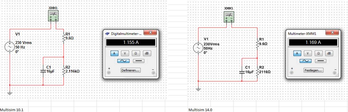
difference of simulation between multisim 10.1 and 14.0
I've been using Multisim 10.1 for check and create examples for students and want to spend 14 Multisim. Simulating a small ac-circuit I got different using multisim 10.1 and 14 results.
The result of multisim 10.1 is identical with the manual solution.
No idea, what could be the problem?
concerning
blanne
Hi Blanne:
The default setting of simulation in Multisim is letting his engine to automatically determine the TMAX, the maximum allowed timestep. In version 13, we have modified this code in such a way that it will leave the slower to simulate faster real-time frequency circuits, we did this in order to accelerate simulations as requested by users. Most of the time, this change has worked as expected, but your circuit is a clear example of a negative effect of this change. Its accuracy is affected by larger time.
In your evaluation of Multisim 14, you can quickly change that. Click on the Interactive analysis button in the toolbar to open the properties of the analysis and in the analysis of Simulation Interactive > look tab crawl settings for the checkbox control labeled step of maximum (TMAX), place a check and let it set to 1e-005. Make your simulation again and you will now see the 1.155 a result in the multimeter.
(Version 14 has been automatically calculate the TMAX as 1.25e - 003)
I'll file a defect report so we review how automatically determine us TMAX so he will not state as in this example. I hope my explanation helps you advance your evaluation of the software.
Kind regards
-
Digital electronics FPGA Board Hardware Driver for Windows 10
My son just made me aware that his school has a dozen of National Instruments Digital Electronics FPGA boards, but they have never been able to get them to work or actually use them in the curriculum. It seems that he has left his instructor know that I worked with FPGA Xilinx for more than 10 years and now everyone counting on me to get these maps work. The issue seems to be the USB driver. According to the manual, I tried DEFB2012_5_2.exe which simply refused to run on this machine Win 10 x 64. DEFB_4_3.exe ran, but complained that LabView components have not been installed and that it would not continue. Could someone tell me please how to install USB driver ONLY so that we can download files of bits with IMPACT? In terms of a school budget, the investment they have in these maps is not negligible. Thank you.
Hello Dave and TGregor,
I hope I can clear some things here. I'm sorry that you run in so many questions with your boards OF FPGA.
First of all, direct responses:
The LabVIEW FPGA 2015 driver should install the components needed to use the Board with Xilinx tools on WINDOWS 7, it will not work on any system more recent that the pilot has been developed before the release of Windows 8 and 10.
http://www.NI.com/download/NI-Digital-Electronics-FPGA-Board-driver-software-2015/5857/en/
My recommendation for Windows 8 or 10 is rather install Xilinx ISE you find on Xilinx website or on the downloads page OR:
https://www.Xilinx.com/products/design-tools/ISE-design-suite.html
http://www.NI.com/download/LabVIEW-FPGA-Module-2016/6231/en/
The difficulty that you face here is that tool Xilinx ISE is officially supported only on Windows 7 and below. So even though I think it will work (and it will move to the difference in the link of the above driver OF FPGA) for Windows 8 and 10, you can continue to deal with certain issues.
Now you are all looking to program the FPGA using an HDL, Multisim and LabVIEW? If you just use an HDL, you should be all set to go and in the dev environment, you had planned using the program. Circuit design of Multisim 'S simulation tool which includes a complete library of graphic digital components. A digital circuit can be built using the graphical logic gates in Multisim then downloaded directly on the FPGA without first having to learn VHDL or Verilog. It is quite popular among the logical classes digital introduction and we can help you by establishes that as well if you are interested.
For anyone else who might stumble upon this page, I want to make sure you are all aware that, while the Board of Directors OF FPGA is still supported and sold, it has been developed a number of years and has recently been replaced by the Council for development of the digital system (DSDB)that uses a 7020 architecting and has much periphrials more to the program than the FPGA OF. So I know that it is not useful for the current issue, but anyone looking for if they would like to buy more OF FPGA boards, I recommend watching the DSDB instead.
Thank you!
-
I'm using LabVIEW-Multisim co-simulation for ordering a buck converter circuit. When I run the VI which controls the converter circuit in Multisim, I get an error code-2367. Specifically, its this error:
External model buckconv.vi/Control & Simulation loop
doAnalyses: Timestep too small(M202)
I think that the error is the framework of simulation in Multisim, but I do not know what parameters to change so that I can solve the problem.
Hello
Normally for a problem of scaling of the timestep I would adjust the tolerance values. In your loop control of Simulation, if you pull the bar to the left, there are 2 options for tolerance (relative and absolute). Try decreasing the accuracy of these (instead of e-12, e-08 of use). Also the minimum and maximum values of stepsize control are there as well if you can try chaning those. Let me know if it works.
Best regards
-
by using labview co-simulation, how to control the PWM market factor in multisim
I am new to the use of Multisim with LabVIEW using co-simulation. I would like to ask if there is a PWM component in Multisim, which can have its cycle have to be controlled using LabVIEW? I have an algorithm in LabVIEW that returns the duty cycle values between 0 and 1, representing the percentage of duty cycle.
How can I control the PWM market factor in Multisim using LabVIEW co-simulation?
Thank you very much
SPECTRUM
Hi spectrum,
In Multisim, find items based on functionality, there are some PWM models in the database. Take a look at this knowledge base if you don't know how to search for parts:
http://digital.NI.com/public.nsf/allkb/7309A5CABC677296862577ED006EC99E
Also, take a look at this knowledge base:
http://digital.NI.com/public.nsf/allkb/EF391C48CF71AE4F862571B900644F84
This article shows you how you can get Mutlisim and LabVIEW to co-simiualte:
http://www.NI.com/white-paper/13663/en
I hope this helps
-
Complete equipment of simulation using LabView, Multisim, and MAX (easy answer accepted!)
Hello, all!
Sorry, I'm new, but I checked around for a definitive answer on this, but I'm not 100% sure. I learn LabView for a physics of upper-division course. We use hardware (DAQ - MX) and a mixture of laboratory equipment - mainly stuff such as voltmeters, oscilloscopes and test setup with simple components. I also work with NIM instrumentation, but that's secondary to my needs here. So, when I'm away from the school, is it possible to make a complete simulation of my classroom work using LabView, Multisim (for my model) and the measurement and Automation Explorer (for the acquisition of data-MX)? I know I can create a circuit and drop it in Labview, but I'm not sure on the acquisition of data. I hope for what is a "seamless" reconstruction of what I do in class. I can't take a simple 'yes' or ""; as long as I know it's possible, I can find the solution.
Thanks for the help!
I wrote 'sim' screws in many situations where I need to work away from the hardware store. I think that MAX has a few features, but you may be limited in the types of signals, you can simulate.
For my sim screw, I make a copy of the original VI with ".sim" added file name. I also change the icon in a characteristic way to identify the version of the sim card on the BD. In this way the two VI have the same connector pane and are interchangeable on the BD structure. disable the diagram can be your friend here. Inside of the VI of sim, I generate the signal in any form I want. You can also add additional if necessary controls.
Lynn
-
Multisim simulation of co error
Hello
When you perform a simulation in Labview (using a model of Multisim) in the Loop Simulation & control, sometimes a small window pops up with the error: Multisim is closing due to the error... (or something like that, I don't use multisim in English) even if I did not open at all Multisim. I think that it opens in the background and it closes because of an error.
If someone could help me, I would be very grateful...
Thank you
Ussr123
Hello
I think I already know what the problem was. I was providing some input values in my file of Multisim simulation. These values were floating point numbers, and sometimes with a micro digits after the comma. It seems that Multisim couldn't handle it. After cutting all the numbers they came after the comma, leaving only 2 or 3, the error seemed no more.
I hope I could help, if everyone will head the same error, try to think of cutting the floating numbers to real numbers.
Ussr123.
-
A simulation of Multisim 12 in labview11 display
Hi admin, I simulate a circuit with Multisim, it works well, I mysignal, I aqueillir this signal, labview, I still install the resource kit, I plugged the connector, I have no evidence for labview multisim12 in2011, how?
Hello
I don't know what your problem is. Please take a look in the link below. It shows you what you need to be able to use co-simulation.
http://zone.NI.com/DevZone/CDA/tut/p/ID/13663
I hope this helps.
-
Execution of Multisim with Labview
Hey,.
I'm trying to convert a series of laboratories studying for a class of dynamic systems run on a newer, better set up. Previously, the laboratory, I'm working on that took input from a sensor, fed entry through an analog circuit that feeds the output of this circuit a Labview VI. My question is, which is possible by using a Multisim simulation instead of a physical circuit? I found volumes about Labview screws running in Multisim, but nothing about a taking a Multisim circuit inlet VI. If this is possible, what configuration do you suggest?
-
How to multisim 11 files (.ms11) work in labview
I designed a circuit converter DC - DC step in Multisim 11. Is it possible that I can use this circuit as a VI in LabVIEW? I have a VI algorithm that hopefully allows you to control the cycle circuit converter DC / DC that I drew.
Thank you
Hi SPECTRUM.
Multisim 12, a new feature called co-simulation aims exactly this effect. You can have a circuit in Multisim and it can simulate and your LabVIEW code. For more information, please read the article below:
http://www.NI.com/white-paper/13663/en
You will not be able to do it with a file of version 11. You can try to use the Multisim LabVIEW toolkit to communicate between Multisim and LabVIEW but is not the same thing as co-simulation.
https://decibel.NI.com/content/docs/doc-4088
I hope this helps.
-
Multimeter simulation Multisim not showing after reading press simulation
I'm running student multisim version 14. I made a very simple circuit and to place two multimeter and run a scan dc.
But the problem I am experiencing that I'm window calculation but multimeters not show any value of simulation.
can someone help me understand this please.
Hi shabeesatsangi,
The meter components are intended to be used during the interactive simulation. When you run the DC OI analysis, you will see the results in a table in the grapher.
To display the values in your multimeters, change your simulation mode to Interactive and run the simulation.
I hope this helps,
Jeff
National Instruments
Maybe you are looking for
-
Auto sign WiFi appear after startup mac
Hello I click on network/forward, then I check all the boxes under "require administered or permission of": creation of computer to computer network; change network; activate wi - if on or off. Until I stop Mac, I turned off wifi. This means that, i
-
Pavilion 13-b080sa: Update Options
HelloI'm trying to find out if it is possible to upgrade the processor, RAM and graphics card than the 13-b080sa Pavilion? The question which is the specification I wan't to least an i5 processor, is not available in a 13.3-inch model. I can here als
-
15 - f039wm has no power after upgrade memory (or disk).
After swapping the existing A-DATA 4 GB SODIMM and its replacement by a (Samsung) InnoDisk 8 GB M3SW - 8GSSDC0C - D, the laptop won't turn on, turn on or show any sign of life. It gives me no opportunity to "quickly press ESC, then press F10." After
-
HP ENVY laptop - 15-k201ne: need recommendation! M.2 SSD
Hello I need help in the choice that can right ssd 256Go m2 laptop as the maintenance and Service Guide shows that it can withstand 2280 (256 GB SATA (MLC) m2 / 256 GB SATA (TLC) m2) After much research, I am very confused because a lot of people her
-
Calendar Gadget does not properly.
My calendar gadget shows a red white Tablet (not calendar) and clicking on the side it does not open the tablet. Seems to have happened with the last update. Was fine before this.