Continuous signal creation (using the PFI channels?)
Hello
I am new to the use of OR and its interfaces. I use the USB-6221, with its C API.
I need to create multiple channels of continuous digital output with the cycle of the frequency and the duty.
I used DAQmxCreateCOPulseChanFreq for the crt0 and crt1 channels and it works fine, but I need a few lines.
Can I use the channels of the PFI (PFI0-4 for example) for this purpose?
With the help of the DAQmxCreateDOChan I can set the PFI desired channels as DO, but how can I create the signal desired on these channels?
Best regards
Danny.
Howdy Danny!
If you try to build a train of digital pulses with a frequency cycle and specified duty then using counters shipped from the USB-6221 is certainly the way to go. Unfortunately, as you have discovered there are only two meters of material available on the USB-6221 (Ctr0 and Ctr1).
Fortunately, you can also use the digital output lines to efficiently create a train of pulses with a frequency cycle and specified duty. You will need create a table of examples which, when released at the specified sampling rate, looks like a period of your waveform. For example, if my sampling rate is 1 MHz and I want to create a square wave of 100 kHz and a cycle of operation of 20% low high/80% I would generate the following examples:
{1, 1, 0, 0, 0, 0, 0, 0, 0, 0, 0, 0}
Please let me know if this description is clear or if there is anything I need to explain more in detail.
Kind regards
Tags: NI Hardware
Similar Questions
-
Hello
I want to generate the continuous signal and at the same time I want to read that signal that I generate using a single card DAQ. I want to generate signal and the received signal is synchronized and in phase.
I looked at several samples on the sync, but it quiet confusing. One using the same clock of entry while the other use a trigger to start. I use the PCI-6024E DAQ card.
Can someone help me in this regard?
In two of these screenshots, the task to HAVE started first (that's what you want, because it is the task of the slave).
Typically for AO, you can simply write a unique period of your waveform, and then regenerate again and again. Your waveform would be preset before the task starts. If you need to update the waveform on the fly according to enter programming during execution of the task, you would disable the regeneration. In addition, if the wave form is such that it cannot be easily represented by a predefined buffer (for example, it is a strange frequency which is not a same ditch at the bottom of the sample clock), then non-regeneration is the way to go.
Best regards
-
Problem of test Signal before using the TCP connection
Right now my application uses a SocketConnection TCP to communicate with a remote server. It works fine, but I'm trying to make sure that my program can correctly handle the situation to move to an area with no coverage.
When I run my application, if I uncheck the box "on the cover" for GSM and CDMA under Network properties, my app fine until it calls the OutputStreamWriter.write () function to send something on the socket connection. I have it in a try/catch block, but it just seems to hang instead of throwing an exception.
How can I check the signal before attempting to send data on the SocketConnection?
To facilitate clear life upwards, here's the order of what happens:
1 application starts on the cover.
2 SocketConnection made successfully.
3 OutputStreamWriter successfully SocketConnection.
4. coverage is lost
5 OutputStreamWriter.write () is called, but freezes instead of throwing an exception.
The socket connection output stream write operations do not throw an exception when there is no coverage is the correct behavior. That's because on cellular networks the IP tunnel to the carrier (and therefore the TCP connections on this tunnel) survives loss of coverage. For example, if your application opens a connection TCP from a BlackBerry, then the BlackBerry loses coverage, then take cover, say, 1 minute later, the TCP connection opened by your application will continue works fine, unless intermediate network component or your server closes the connection due to inactivity.
-
Hello
why we use rman channel. ?
Concerninguser13367819 wrote:
Hellowhy we use rman channel. ?
Concerning
When you run rman backup/restore operation must create according to session. Thus the creation of these session to assign channels.
Handle: user13367819
Status level: Beginner
Join date: July 6, 2010
Messages total: 44
Total Questions: 29 (22 pending)Why you do not close your questions answers if they actually answered?
Close the thread as answered and mark message correct/useful. -
Timestamp of the external Signal triggered using the PCIe-6351
Hello
I use a PCIe-6351 to acquire externally triggered data. My block diagram looks almost exactly at this link in the section A. Posttriggered Acquisition with a digital start triggering:
http://www.NI.com/white-paper/4329/en
As you can see he is a straightforward acquisition. My trigger signal is on PFI0 and it is supposed to occur at regular intervals. However, I started to suspect that it varies in time. For example, if this is supposed to happen every 2 milliseconds it can range from 1.9 to 2.1 milliseconds. Is it possible for DAQmx record the time at which each trigger occurs? I realize that it will not be synchronized with the time on the PC, but as long as I can have a time stamp of each trigger I can subtract each time individual time of the first condition for the time between triggers.
Thank you!
Steve
MR. O,.
Thanks for the reply. My system is set up to acquire many points of data at a relatively fast pace, so I their stamp on the data acquisition card and only download on the PC once the acquisition is completed. My understanding is that writing to file measure vi set a timestamp whenever he writes to the file - not for each individual data point. Is this correct?
Steve
-
XML part that is customized by using the HTTP channel
Hi all
I have obligation where 2 partners will display a custom XML (same pattern for both partners) load via a B2B http url.
I need your help to configure the generic Http channel for both partners and based on a particular value in the payload, respective contract should be triggered.
Currently, I get error Protocol for Identification of Document.
Help, please.
Thank you
Monica
Please make sure that the IP address, you receive as part of HTTP header is the same as that configured.
Concerning
Nebot
-
I have attached the screen shots that capture "devices and Interfaces", "Logical names" and the "driver Session."
-
How the PFI to go top-to-bottom with sample clock?
Hello world!
I am very new to LabView and I try to do something very simple in the NI PCI-6534 and still not get anywhere (or do not know if it is the limitation of the hardware)
My request is to acquire digital data of 2 channels (16-bit each) of our Board custom designed analog-to-digital.
So far, I am in a position to acquire a finite amount of sampling digital (say 100000) and using a trigger to start (PFI6) to start the acquisition of our custom card board. Just to let you know that I'm feeding the PCI-6534 an external clock of 20 MHz by PFI2.
However, I want to send a signal to trigger recognition (high/low-rising edge) to our personal advice, saying: he did the acquisition of 100000-sample.
My problem is that whenever I try to use the lines of PFI signal with an internal sample clock, I get an error saying that I can't use the PFI lines with any sample clock. But my goal is to use a rising edge (low-high) to trigger back.
So far, I can pull the PFI4 high and used a timer to make it low. But the resolution of the timer is milliseconds (software) range. I would like to have at least a few microseconds.
I also tried using implicit since manual said that it does not require any clock but still get no result. Also, I couldn't find an example of implied clock and don't know if PCI-6534 supports.
Note that I'm able to use the clock synchronization of sampling with other DIO (Port 0 to Port 3) lines and get the result I want. However, I would need to use all our custom Board 32 - DIO for analog-to-digital data lines. So, using the line of PFI laccuse is the only choice.
If you have ideas/pointers, please throw it at me, I'll try them. Thanks a lot for your help!

See you soon,.
Yaseen KhanHi ykhan,
After validation, I noticed that it will not really work for what you are trying to do. The PFI lines on your 6534 are I/O static only as shown in the DAQmx help.
You will be able to control these lines, but only with software timing. You should be able to call and argue by their physical channel name. I hope this helps!
Kind regards
-
Change the shape of the output signal without initializing the new process of output signal
Hello!
How to change the shape of the output signal produced on the output channel without initializing the new process of output signal?
Thank you
Yes, you can do the same thing without count/killing the task all the time.
Attached VI shows how to use redeclenchables AO in the same way, using a meter like time base for the AO.
Please note that attached VI uses the same Subvi as in the example you posted before.
Christian
-
How to set up the PFI lines as input to PXI-6713 module
Hello
I have 6713 PXI module in my chassis PXI-1044. I have configured the PXI-6713 module to geneate some analog signals to my Board of Directors.
Council inturn process this analog signal and answers in return the status signals through a registry to the Board of Directors. In my application, the status bits in the register state of the governing body are mapped on the PFI 0:3 bits of the PXI-6713 (pins 11,10, 42 and 43) module.
My query is how can I configuration lines PFI as 6713 PXI module entries to read these status bits?
May be less than the explanation could give you little more information w.r.to my request.
When I use NI USB - 6008 module to read the same bits, because this unit has 12 e / s digital, I was able able to read the status bits in the last 4 digital lines by setting up those digital lines as input.
In the PXI-6713 module, I have only 8 digital lines. These 8 digital lines I used to send digital signals to the Board of Directors. I find myself with no digital i/o. Therefore, I could not use these digital lines. I'm left with only one option to use. Joana re PFI lines. Also the bits of status in the axis of the room are mapped such that the bits can be read through the PFI lines.
I was wondering do we have any example code to use inorder to read these status bits to the Board of Directors using the PFI lines.
Please let me know if you need more information to help out me.
Thank you.
Hello
When using the PFI PIN as input, you can individually configure each PFI for edge detection or level and the selection of the polarity. This information of PFI are referenced in the manual of Series DAQ Analog Output on page 6-1 (http://www.ni.com/pdf/manuals/370735e.pdf). Unfortunately, the PXI-6713 PFI lines are able to time a signal input and output for functions, AO or counters/timers. The ability to create static DI of the PFI lines is not available for the PXI-6713. However, some cards have this capability. The latest National Instruments products with PFI lines have the option of setting as PFI lines:
- Static digital input
- Static digital output
- Input signal of sync for functions HAVE, AO, DI, or counters/timers
- Output signal of the calendar functions HAVE, AO, DI, or counters/timers
(http://digital.ni.com/public.nsf/allkb/14F20D79C649F8CD86256FBE005C2BC4)
When the static value such as DIO, PFI lines are assigned to a different port (for example. PFI0-7 is Port1). More details on this subject can be referenced at:
http://digital.NI.com/public.nsf/allkb/DA2D3CD0B8E8EE2A8625752F007596E1
http://digital.NI.com/public.nsf/allkb/862567530005F09E8625677800577C27
-
in some sites, there are two menus in competition and you can't use the bottom menu
I've been using The Shopping Channel years but since I loaded Firefox I can't open certain areas of this site (and other sites). Menus appear to be in competition with each other. There is a regular menu below and a new "BOLD" menu on the top. If I need to look for the customer service, it is blocked by this "BOLD" menu on the top.
I wrote to them several times, but they say that the problem is at my end.You can watch one of the extensions I posted above to increase the zoom of page and minimum font size.
- Default FullZoom Level: https://addons.mozilla.org/firefox/addon/default-fullzoom-level/
- NoSquint: https://addons.mozilla.org/firefox/addon/nosquint/
-
Re: Satellite L735 PSK0CE: WLan and BT use the same frequency
Hello world
I reinstalled my Toshiba Satellite L735 - PSK0CE with Windows 7, until the one and download all the drivers for it, I did not too Wirelles conection, Lan and the wirelless use the same channell radiofrecuency than Bluetooth
Can you help me with this problem?
Thanks in advance
Post edited by: aku - aku
Hello
WiFi and BT use the same frequency. For the most part this isn't a big problem but in case you notice a few connection problems with WLan or BT, you must disable WLan using BT or must turn off BT if you want to use the WLan.
-
How can I get a continuous square wave to the duty cycle of 50% on one of the analog lines?
Hello, I had recently just buy an analog card to our system, and I'm still very new to labview. I have the PXI-6723, and I need to produce a wave square of 0 to 5 volts continuously. I used the square wave generator and used a writing funtion to one of the ports. This produces a momentary wave and that's it. I tried to put some time a loop around the square and watched as wave function. It produces constantly plots, but the write function always has the same thing. If I am the writing inside the loop function I get errors. Any help would be greatly appreciated. Thank you, Fred
Another function to generate the square wave, to change the generation of waveform buffer (the Subvi used) and to connect a control at the entrance to offset from the base generator functions. or simply use the add function on the output waveform.
-
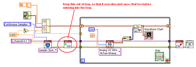
It seems only to read 200 samples and then stop. Shouldn't get a chart to continuous wave after using the shift over a time register loop?
You must remove VI begin to break out of the loop...
You can not 'start' a task that is already running...You also remove the VI start completely from your code... If you do not use start VI, a measurement task starts automatically when executing the DAQmx reading VI.
Find the attached VI.
-
Using the output with 6009 or 6216 possible buffer?
Hello
I have a USB6009 and a USB6216. I need to generate a signal by using the analog output and I would use the output buffer. My questions are:
-The USB6009 has an output buffer? I always get an error, but I know from experience that this device is very limited, so I wonder if they have not only an output buffer... (Programs in input buffer are not a problem at all).
-J' took the USB6216 and I tried the example WfmGenUp.c downloaded from somewhere in the area of the developer (sorry I lost the link but fix the code) but I am not all analog output signals and after you press ENTER to stop the program (depending on the show) I get this error message:
NO MORTALS RUN - TIME ERROR: 'WfmGenUp.c', line 113, col 9, id thread 0x0000088C: DAQmxStopTask function: (is-200016 return value [0xfffcf2b0]). Measurements: On-board memory precision passing. Due to the limitations of system and/or the bandwidth of the bus, the driver could not write data to the device fast enough to track the rate of output of the device. Reduce your sampling rate, change the method of transfer of data (from interruptions on DMA), use a product with more on-board memory or reduce the number of programs that your computer runs simultaneously. Task name: _unnamedTask<0> Code of State:-200016
I don't know if the problem is just that the 6216 does not support the output buffering or the other...
-So, if the output control is not supported by 6009 or 6216 what would be the best way to constantly generate signals to 100 s/s?
Thank you very much
Kristel
Hi Ryan,
the USB-6009 case has 150 s/s softwaretimed AO, so you won´t be able to use AO stamped with the module.
The USB-6216 supported in the analog output buffer, just follow the recommendations that the driver gives you,
for example by reducing the sampling frequency, if there is an overflow memory due to the limitations of system and/or the bandwidth of the bus.
Experiment with the parameters and the basic to see in what range of sampling it works.
You can find appropriate examples
ANSI C:
C:\Dokumente und All Anwendungsdaten Users\Dokumente\National Instruments\NI - DAQ\Beispiele\DAQmx C\Analog Out\Generate Voltage\Cont Gen Volt Wfm - Int Clk ANSI
LabWindows CVI:
C:\Dokumente und Users\Dokumente\National Instruments\CVI\samples\DAQmx\Analog Out\Generate Voltage\Cont Gen Volt Wfm - Int Clk Anwendungsdaten All
Maybe you are looking for
-
I downloaded several times, but the web plugin VLC VLC 2.1.5 version 2.1.3 has been how to date?
I downloaded it on my VLC media player 2.1.5 pc but when I went to see the updates of the plugin, vlc web plugin remained at version 2.1.3 How to upgrade the plugin?
-
Artists showing several times but in the same media folder?
Hi people, A bit of an irritating problem and that, despite several attempts to trouble shoot, I have been unable to solve. As iTunes traditionally organizes the library along the lines of the "Album Artist", I always used this tab to keep my library
-
old photos will not disappear - 2nd generation ATV
2nd generation Apple TV Model number: MC572LL/A Version: 6.2.1 I work in a marketing agency that uses two Apple TV in the hall to showcase some of our work as a screensaver constantly loop... and I am responsible to keep them up-to-date. Until I can
-
Just picked up fable 3 and updated my graphics card. Whenever I have save my game it says that the file is corrupted and I can't load my last record.
-
Windows xp professional compatibility with card mother i5 to intel
HelloI want to upgrade my pc to the card mother i5 intel. Windows xp professional compatible?